manuals.online logo
Brands
  1. Home
  2. •
  3. Brands
  4. •
  5. Nautel
  6. •
  7. Transmitter
  8. •
  9. Nautel ND500II Owner's manual

Nautel ND500II Owner's manual

e-mail: [email protected]
web: www.nautel.com
Nautel Maine Inc. Nautel Limited
201 Target Industrial Circle, 10089 Peggy's Cove Road,
Bangor, Maine USA 04401 Nova Scotia Canada B3Z 3J4
Phone: (207) 947-8200 Phone: (902) 823-3900
Fax: (207) 947-3693 Fax: (902) 823-3183
ISO 9002 REGISTERED ISO 9001 REGISTERED
© Copyright 2003 NAUTEL. All rights reserved
TECHNICAL INSTRUCTIONS
ND500II
125 WATT
RADIOBEACON TRANSMITTER
(190kHz to 1250kHz and 1600 kHz to 1800 kHz)
DOUBLE SIDEBAND - NO VOICE
NAPE72 Keyer PWB
NAPC22G Monitor PWB
Original Issue ...............15 September 2003
Change 1.......................01 November 2003
Change 2......................15 September 2004
RADIOBEACON TRANSMITTER
ND500II (125 WATTS) DOUBLE SIDEBAND - NO VOICE
Effective Pages (Page 1)
15 September 2004
LIST OF EFFECTIVE PAGES
The list of effective pages lists the status of all pages in this manual. Pages of the original issue are identified by a
zero in the Change # column. Pages subsequently changed are identified by the date of the change number. On a
changed page, the text affected by the latest change is indicated by a vertical bar in the margin opposite the changed
material.
Original ................................................ 15 September 2003
Change 1 .............................................. 01 November 2003
Change 2 .............................................. 15 September 2004
Total number of printed sides in this manual is 173 as listed below:
CHANGE CHANGE
PAGE # DATE PAGE #. DATE
Title 2 15 September 2004
Title (Rear) - Blank
Effective (1) 2 15 September 2004
Effective (2) 2 15 September 2004
Effective (3) 1 01 November 2003
Effective (4) - Blank
Safety (1) 0 15 September 2003
Safety (2) 0 15 September 2003
Safety (3) 0 15 September 2003
Safety (4) 0 15 September 2003
Warranty (1) 0 15 September 2003
Warranty (2) 0 15 September 2003
Contents (1) 1 01 November 2003
Contents (2) 0 15 September 2003
Contents (3) 0 15 September 2003
Contents (4) 0 15 September 2003
Contents (5) 0 15 September 2003
Contents (6) 0 15 September 2003
Contents (7) 1 01 November 2003
Contents (8) 1 01 November 2003
1-1 0 15 September 2003
1-2 0 15 September 2003
1-3 0 15 September 2003
1-4 0 15 September 2003
1-5 1 01 November 2003
1-6 - Blank
2-1 1 01 November 2003
2-2 1 01 November 2003
2-3 1 01 November 2003
2-4 1 01 November 2003
2-5 1 01 November 2003
2-6 1 01 November 2003
2-7 1 01 November 2003
2-8 1 01 November 2003
2-9 1 01 November 2003
2-10 1 01 November 2003
2-11 1 01 November 2003
2-12 1 01 November 2003
2-13 1 01 November 2003
2-14 0 15 September 2003
3-1 0 15 September 2003
3-2 0 15 September 2003
3-3 0 15 September 2003
3-4 0 15 September 2003
3-5 0 15 September 2003
3-6 0 15 September 2003
3-7 0 15 September 2003
3-8 0 15 September 2003
3-9 0 15 September 2003
3-10 0 15 September 2003
3-11 0 15 September 2003
3-12 0 15 September 2003
4-1 0 15 September 2003
4-2 0 15 September 2003
4-3 0 15 September 2003
4-4 0 15 September 2003
4-5 0 15 September 2003
4-6 0 15 September 2003
4-7 0 15 September 2003
4-8 0 15 September 2003
4-9 0 15 September 2003
4-10 0 15 September 2003
4-11 0 15 September 2003
4-12 0 15 September 2003
4-13 0 15 September 2003
4-14 0 15 September 2003
4-15 0 15 September 2003
4-16 - Blank
5-1 0 15 September 2003
5-2 0 15 September 2003
RADIOBEACON TRANSMITTER
ND500II (125 WATTS) DOUBLE SIDEBAND - NO VOICE
Effective Pages (Page 2)
15 September 2004
LIST OF EFFECTIVE PAGES (Continued)
CHANGE CHANGE
PAGE # DATE PAGE # DATE
5-3 0 15 September 2003
5-4 0 15 September 2003
5-5 0 15 September 2003
5-6 0 15 September 2003
5-7 0 15 September 2003
5-8 0 15 September 2003
5-9 0 15 September 2003
5-10 0 15 September 2003
5-11 0 15 September 2003
5-12 0 15 September 2003
5-13 0 15 September 2003
5-14 0 15 September 2003
5-15 0 15 September 2003
5-16 0 15 September 2003
5-17 0 15 September 2003
5-18 0 15 September 2003
5-19 0 15 September 2003
5-20 0 15 September 2003
5-21 0 15 September 2003
5-22 - Blank
6-1 0 15 September 2003
6-2 0 15 September 2003
6-3 0 15 September 2003
6-4 0 15 September 2003
6-5 0 15 September 2003
6-6 0 15 September 2003
6-7 0 15 September 2003
6-8 0 15 September 2003
6-9 0 15 September 2003
6-10 0 15 September 2003
7-1 0 15 September 2003
7-2 0 15 September 2003
7-3 0 15 September 2003
7-4 0 15 September 2003
7-5 0 15 September 2003
7-6 0 15 September 2003
7-7 1 01 November 2003
7-8 1 01 November 2003
7-9 1 01 November 2003
7-10 0 15 September 2003
7-11 0 15 September 2003
7-12 1 01 November 2003
7-13 1 01 November 2003
7-14 0 15 September 2003
7-15 0 15 September 2003
7-16 0 15 September 2003
7-17 0 15 September 2003
7-18 0 15 September 2003
7-19 0 15 September 2003
7-20 0 15 September 2003
7-21 0 15 September 2003
7-22 0 15 September 2003
7-23 0 15 September 2003
7-24 0 15 September 2003
7-25 0 15 September 2003
7-26 1 01 November 2003
7-27 1 01 November 2003
7-28 1 01 November 2003
7-29 1 01 November 2003
7-30 0 15 September 2003
7-31 0 15 September 2003
7-32 0 15 September 2003
8-1 0 15 September 2003
8-2 0 15 September 2003
8-3 0 15 September 2003
8-4 0 15 September 2003
8-5 0 15 September 2003
8-6 0 15 September 2003
8-7 0 15 September 2003
8-8 0 15 September 2003
8-9 0 15 September 2003
8-10 0 15 September 2003
9-1 0 15 September 2003
9-2 0 15 September 2003
9-3 1 01 November 2003
9-4 - Blank
SD-1 1 01 November 2003
SD-2 2 15 September 2004
SD-3A 1 01 November 2003
SD-3B 1 01 November 2003
SD-4 0 15 September 2003
SD-5 0 15 September 2003
SD-6 0 15 September 2003
SD-7 0 15 September 2003
SD-8A 0 15 September 2003
SD-8B 0 15 September 2003
SD-9 0 15 September 2003
10-1 0 15 September 2003
10-2 1 01 November 2003
MD-1 0 15 September 2003
MD-2 0 15 September 2003
MD-3 0 15 September 2003
MD-4 0 15 September 2003
MD-5 0 15 September 2003
MD-6 0 15 September 2003
MD-7A 1 01 November 2003
MD-7B 1 01 November 2003
MD-8 0 15 September 2003
RADIOBEACON TRANSMITTER
ND500II (125 WATTS) DOUBLE SIDEBAND - NO VOICE
Effective Pages (Page 3)
15 September 2004
LIST OF EFFECTIVE PAGES (Continued)
CHANGE CHANGE
PAGE # DATE PAGE # DATE
MD-9 0 15 September 2003
MD-10 0 15 September 2003
MD-11 0 15 September 2003
MD-12 0 15 September 2003
MD-13A 0 15 September 2003
MD-13B 1 01 November 2003
MD-13C 1 01 November 2003
MD-14 1 01 November 2003
MD-15 0 15 September 2003
MD-16 0 15 September 2003
MD-17 0 15 September 2003
RADIOBEACON TRANSMITTER
ND500II (125 WATT) DOUBLE SIDEBAND - NO VOICE
Safety (Page 1)
15 September 2003
ARTIFICIAL RESPIRATION (MOUTH-TO-MOUTH)
(a) START MOUTH-TO-MOUTH BREATHING
IMMEDIATELY. SECONDS COUNT. Do not wait to
loosen clothing, warm the casualty, or apply stimulants.
(b) ASSESS RESPONSIVENESS OF CASUALTY. Do not
jar casualty or cause further physical injury (Figure 1)
(c) IF POSSIBLE, SEND A BYSTANDER TO GET
MEDICAL HELP. Do not leave casualty unattended
(Figure 2)
(d) CHECK CAROTID PULSE (Figure 3)
(e) LAY CASUALTY ON HIS/HER BACK and place any
available jacket or blanket under his/her shoulders.
(f) TILT THE HEAD BACK AND LIFT THE CHIN to open the
airway (Figure 4)
(g) PINCH CASUALTY’S NOSE AND EXHALE TWO SLOW
BREATHS INTO CASUALTY (Figure 5)
(h) REMOVE YOUR MOUTH and check for breathing
(Figure 6)
(i) CONTINUE GIVING ONE BREATH EVERY FIVE
SECONDS without interruption. If any air is retained in
the stomach after exhalation by casualty, press gently on
stomach to expel air.
(j) IF CHEST DOES NOT RISE CHECK for obstruction in
casualty’s mouth: clear foreign material using your finger,
tissues, etc. Use chin lift and recommence mouth-to-
mouth breathing.
(k) WHILE MOUTH-TO-MOUTH BREATHING IS
CONTINUED have someone else:
(a) Loosen casualty’s clothing.
(b) Keep the casualty warm.
(l) DON’T GIVE UP. Continue without interruption until the
casualty is revived, or until a doctor pronounces the
casualty dead. Four hours or more may be required.
(m) DO NOT PROVIDE ANYTHING ORALLY while victim is
unconscious.
1
2
3
4
5
6
RADIOBEACON TRANSMITTER
ND500II (125 WATT) DOUBLE SIDEBAND - NO VOICE
Safety (Page 2)
15 September 2003
GENERAL RULES FOR TREATMENT FOR BURNS, BLEEDING, AND SHOCK
1. After casualty has revived, treat for injuries and shock.
2. Reassure casualty.
3. Try to make him comfortable.
4. Keep him reasonably warm but do not apply heat.
5. If thirsty, liquids may be given but no alcohol (no liquids should be given in cases of severe burns).
6. Treat burns or wounds. Infection danger in treating burns or wounds is very great so ensure hands are
clean and do not handle affected areas more than necessary.
7. Do not apply salves, grease, etc. to burns.
8. Do not remove burned clothing which adheres to the skin or break blisters.
9. Cover the burn with a dry sterile dressing, piece of sheeting, etc.
10. Bandage lightly over blisters where care must be taken to cover and not to break.
11. If severe bleeding of wound, elevate affected area, except in the case of a fracture.
12. Expose wound and apply pressure.
13. Apply dressing, pad and bandage.
14. For burns and bleeding, immobilize injured part using splints if necessary and keep patient in restful
position during removal to hospital or expert medical attention.
15. In all cases, send for medical aid immediately.
RADIOBEACON TRANSMITTER
ND500II (125 WATT) DOUBLE SIDEBAND - NO VOICE
Safety (Page 3)
15 September 2003
ELECTRIC SHOCK - RESCUE METHODS
Electricity can damage the body in a number of ways. It may interfere with the proper functioning of the nervous
system and the heart action, it can subject the body to extreme heat and can cause severe muscular contractions.
The path that the current of electricity takes through the body is important. Currents which pass from hand to hand
or from hand to foot may pass directly through the heart and upset its normal functioning. This threat to life is
related to the amount of current or amperage that will flow through a victim's body. Very little current (as little as
10 milliamps) can result in severe shock or death.
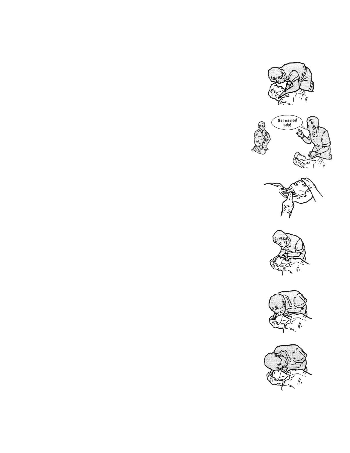
Speed in the application of first aid measures is absolutely essential in cases of electrical injury. As soon as the
victim is freed safely from the source of the electrical current, if breathing has stopped, artificial respiration should
be commenced immediately. If the carotid pulse cannot be felt, external cardiac massage should be commenced
simultaneously. Resuscitation should be continued until the patient is breathing on his own or until medical aid
arrives. Survival rates can be quite high if cardio-pulmonary resuscitation is started within 3 to 4 minutes of the
injury being received.
ACT AT ONCE - DELAY OR INDECISION MAY BE FATAL
1. Turn OFF the electrical source.
2. Commence artificial respiration immediately.
3. Treat for burns, bleeding and shock.
REMOVING A CASUALTY FROM ELECTRICAL CONTACT
LOW VOLTAGE - 0 to 240 volts (household use)
Switch off the current, if possible and time permits. If the switch cannot be located immediately and the supply is
through a flexible cord or cable, the current may be shut off by removing the plug or even breaking the cable or
wrenching free. Never attempt to shut off current by cutting cord with a knife or scissors.
If the current cannot be shut off, the greatest care is necessary in removing the casualty. Household rubber gloves,
rubber or plastic hose (if there is no water in them), a dry unpainted stick or a clean dry rope can be used to free
victim.
HIGH VOLTAGE - 240 volts and up (industrial machines and power lines)
Do not touch any person or equipment in contact with a wire.
Use a dry unpainted pole, clean dry rope, dry rubber or plastic water hose to separate the casualty from the contact.
Keep as far away as possible.
Do not touch the casualty until he is free.
RADIOBEACON TRANSMITTER
ND500II (125 WATT) DOUBLE SIDEBAND - NO VOICE
Safety (Page 4)
15 September 2003
TOXIC HAZARD WARNING
There are devices used in this equipment containing BERYLLIUM OXIDE ceramic, which is non-hazardous during
normal device operation and under normal device failure conditions. These devices are specifically identified in the
equipment manual’s parts list(s).
DO NOT cut, crush or grind devices because the resulting dust may be HAZARDOUS IF INHALED.
Unserviceable devices should be disposed of as harmful waste.
RADIOBEACON TRANSMITTER
ND500II (125 WATTS) DOUBLE SIDEBAND - NO VOICE
Warranty (Page 1)
15 September 2003
WARRANTY
Nautel Limited/Nautel Maine Incorporated, hereinafter referred to as Nautel, guarantees all mechanical and
electrical parts of the equipment for a period of thirteen months from date of shipment.
1. A "Part Failure" shall be deemed to have occurred when the part has become defective, or does not have the
characteristics required for the specified equipment performance:
(a) When the equipment is operated within the design parameters, and
(b) When the equipment is installed and adjusted according to Nautel's prescribed procedures as stated in
the instruction manual.
2. Nautel shall provide replacements for all "Parts" at no cost to the Customer when they become defective
during the warranty period, and upon the return of the defective part.
3. In the event that a "Part" fails during the warranty period and causes damage to a sub-assembly that cannot
be readily repaired in the field, the entire sub-assembly so damaged may be returned to Nautel for repair.
The repairs will be made without charge to the Customer.
4. Where warranty replacements or repair are provided under items 2 or 3, Nautel will pay that part of the
shipping costs incurred in returning the part/assembly to the Customer.
5. Warranty replacement parts and repair, which are provided under items 2 or 3, shall be guaranteed for a
period of ninety days from date of shipment or until the end of the original warranty period, whichever occurs
later.
6. Nautel will not assume responsibility for any charges incurred by other than Nautel employees.
7. Nautel shall have the privilege of investigating whether failures have been caused by factors beyond its
control.
8. Nautel shall in no event be liable for any consequential damages arising from the use of this equipment.
9. When requesting a warranty repair/replacement, please provide complete and accurate information. Observe
the instructions regarding 'Equipment Being Returned to Nautel' on page two of this warranty and provide the
information requested.
10. When ordering spare/replacement parts; please provide complete and accurate information. Refer to the parts
list of this manual for ordering information. Provide as much of the information requested for 'Equipment
Being Returned to Nautel' on page two of this warranty as is practical. The information identified by an
asterisk is the minimum required.
ON-LINE PART QUOTES
Nautel provides an on-line website service (www.nautel.com/in-service.html) where requests for part quotes may
be submitted. Requests will normally be responded to within one working day.
RADIOBEACON TRANSMITTER
ND500II (125 WATTS) DOUBLE SIDEBAND - NO VOICE
Warranty (Page 2)
15 September 2003
FACTORY SUPPORT
TECHNICAL ASSISTANCE
Nautel's field service department provides telephone technical assistance on a 24 hour, seven days a week basis.
Requests by other media (facsimile or e-mail) will be responded to the next working day if received after Nautel's
normal working hours. Contact the appropriate field service centre from the following:
U.S.A. customers use: Nautel Maine Incorporated Telephone 207-947-8200 (24 hours)
201 Target Industrial Circle Facsimile 207-947-3693
Bangor, Maine 04401
All other customers use: Nautel Limited Telephone 902-823-3900 (24 hours)
10089 Peggy’s Cove Road, Facsimile 902-823-3183
Nova Scotia, Canada E-Mail [email protected]
B3Z 3J4 Web www.nautel.com
MODULE EXCHANGE SERVICE
In order to provide Nautel customers with a fast and efficient service in the event of a problem, Nautel operates a
factory rebuilt, module exchange service which takes full advantage of the high degree of module redundancy in
Nautel equipment. This module exchange service is operated from Nautel’s factory in Bangor, Maine and
Hackett’s Cove, Nova Scotia. These two locations allow us to provide a quick turn around service to keep our
customers on the air. During the transmitter’s warranty period, up to thirteen months from shipment, repair and
exchange of modules is at no charge to the customer. When the warranty has expired, a charge of 80% of the
list price for all exchanged modules is made. If the faulty module is returned to Nautel within 30 days, a credit is
issued reducing this charge by one half to 40% of the list price. U.S.A. customers are required to contact our
Bangor, Maine facility. Canadian and overseas customers should contact our Nova Scotia, Canada facility.
EQUIPMENT BEING RETURNED TO NAUTEL
All equipment being returned to Nautel and all requests for repairs or replacements should be marked 'field
return' and addressed to the appropriate Nautel facility.
Complete and accurate information regarding the equipment being returned will ensure prompt attention and will
expedite the dispatch of replacements. Refer to the nameplate on the transmitter and/or the appropriate
module/assembly to obtain name, type, part and serial number information. Refer to the parts list of this manual
or the appropriate service instruction manual for additional ordering information.
The following information should accompany each request:
*Model of Equipment
*Serial number of Equipment
*Name of Part/Assembly
Serial number of Part/Assembly
*Complete reference designation of Part/Assembly
*Nautel's part number of Part/Assembly
*OEM's part number of Part/Assembly
Number of hours in Use
Nature of defect
*Return shipping address
* Denotes minimum information required to order spare/replacement parts
RADIOBEACON TRANSMITTER
ND500II (125 WATTS) DOUBLE SIDEBAND - NO VOICE
Contents (Page 1)
01 November 2003
TABLE OF CONTENTS
Section Page
1GENERAL INFORMATION
1.1 INTRODUCTION ........................................................................................................ 1-1
1.2 PURPOSE AND SCOPE OF MANUAL ...................................................................... 1-1
1.3 PURPOSE OF EQUIPMENT ...................................................................................... 1-1
1.4 FACTORY REPAIR SERVICE.................................................................................... 1-5
1.5 MECHANICAL DESCRIPTION................................................................................... 1-5
1.5.1 CABINET.................................................................................................................... 1-5
1.6 TECHNICAL SUMMARY............................................................................................ 1-5
1.7 SPECIAL TOOLS AND TEST EQUIPMENT .............................................................. 1-5
1.8 GLOSSARY OF TERMS ............................................................................................ 1-5
2THEORY OF OPERATION
2.1 GENERAL ................................................................................................................. 2-1
2.2 TRANSMITTER DESCRIPTION................................................................................. 2-1
2.2.1 POWER SUPPLY (A1) ......................................................................................... 2-1
2.2.1.1 AC Power Source Operation........................................................................... 2-1
2.2.1.2 Unregulated +24V........................................................................................... 2-1
2.2.1.3 +15 Volt DC Regulator.................................................................................... 2-2
2.2.1.4 DC Power Source (Battery)............................................................................. 2-2
2.2.1.5 AC Monitoring................................................................................................. 2-2
2.2.1.6 B+ Monitoring/Inhibit....................................................................................... 2-3
2.2.2 OSCILLATOR/RF DRIVE PWB (A2)..................................................................... 2-3
2.2.2.1 Balance/RF Drive........................................................................................... 2-3
2.2.3 KEYER PWB (A3) ................................................................................................ 2-3
2.2.4 MODULATOR DRIVER PWB (A4)........................................................................ 2-4
2.2.4.1 Mod Enable Switch......................................................................................... 2-5
2.2.4.2 +15V to -15V Converter.................................................................................. 2-5
2.2.4.3 PWM Square Wave Generator....................................................................... 2-5
2.2.4.4 PWM Ramp Integrator.................................................................................... 2-5
2.2.4.5 Variable Pulse-Width Generator ..................................................................... 2-5
2.2.4.6 Linear Attenuator............................................................................................ 2-6
2.2.4.7 B+ Variation Compensation............................................................................ 2-6
2.2.4.8 Low RF Drive Cutback.................................................................................... 2-6
2.2.4.9 Balanced Drive............................................................................................... 2-7
2.2.4.10 Pulse-Width Fault Detector............................................................................. 2-7
2.2.5 POWER AMPLIFIER/MODULATOR (A6)............................................................. 2-7
2.2.5.1 Modulator ....................................................................................................... 2-7
2.2.5.2 Power Amplifier.............................................................................................. 2-8
2.2.6 MONITOR PWB (A5)............................................................................................ 2-8
2.2.6.1 Forward Power/Fwd Pwr Cal........................................................................... 2-8
2.2.6.2 Audio Monitoring............................................................................................. 2-8
2.2.6.3 Monitor's +15V (A) Supply.............................................................................. 2-9
2.2.6.4 Low Carrier Level (-3dB) Detector................................................................... 2-9
2.2.6.5 High Carrier Level (+2dB) Detector................................................................. 2-9
2.2.6.6 Low Modulation Depth Detector...................................................................... 2-9
2.2.6.7 Shutdown Control......................................................................................... 2-10
2.2.6.8 Overmodulation Detector.............................................................................. 2-10
RADIOBEACON TRANSMITTER
ND500II (125 WATTS) DOUBLE SIDEBAND - NO VOICE
Contents (Page 2)
01 November 2003
TABLE OF CONTENTS (Continued)
Section
2THEORY OF OPERATION (Continued)
2.2.6.9 Reflected Power/Refl Pwr Cal....................................................................... 2-10
2.2.6.10 SWR Protection............................................................................................ 2-10
2.2.6.11 Battery Control ............................................................................................. 2-11
2.2.6.12 Mod% Control............................................................................................... 2-11
2.2.6.13 Bypass Control ............................................................................................. 2-12
2.2.7 HARMONIC FILTER (A7) ................................................................................... 2-12
2.2.7.1 Current Probe............................................................................................... 2-12
2.2.7.2 Forward/Reflected Power Probe ................................................................... 2-12
2.2.7.3 RF Monitor Switching.................................................................................... 2-12
2.2.8 RF SYNTHESIZER PWB (A9)............................................................................ 2-13
2.2.9 24-48V POWER SUPPLY PWB (A10, Optional))................................................ 2-13
2.2.10 REMOTE INTERFACE PWB (A11)..................................................................... 2-13
2.2.11 SHUNT TUNING INDUCTOR (L2)...................................................................... 2-13
3INSTALLATION AND PREPARATION FOR USE
3.1 GENERAL ................................................................................................................. 3-1
3.2 TEST EQUIPMENT.................................................................................................... 3-1
3.3 SITE REQUIREMENTS.............................................................................................. 3-1
3.3.1 LIGHTNING/SAFETY GROUND........................................................................... 3-1
3.3.2 ANTENNA SYSTEM............................................................................................. 3-1
3.3.3 ELECTRICAL POWER......................................................................................... 3-1
3.3.3.1 AC Power Requirements................................................................................. 3-1
3.3.3.2 DC Power Requirements ................................................................................ 3-1
3.3.4 ELECTRICAL POWER CABLING......................................................................... 3-1
3.3.5 RF OUTPUT CABLE............................................................................................. 3-1
3.3.6 CONTROL/MONITOR CABLING.......................................................................... 3-2
3.3.7 19-INCH MOUNTING RACK................................................................................. 3-2
3.3.8 EXTERNAL ALARM/STATUS MONITORING FEATURES ................................... 3-2
3.3.8.1 Shutdown Alarm............................................................................................. 3-2
3.3.8.2 High SWR Alarm............................................................................................ 3-2
3.3.8.3 Battery Status................................................................................................. 3-2
3.3.9 VENTILATION...................................................................................................... 3-2
3.3.10 HEATING ............................................................................................................. 3-2
3.3.11 WORK AREA ....................................................................................................... 3-2
3.4 UNPACKING .............................................................................................................. 3-2
3.5 ANCILLARY PARTS .................................................................................................. 3-3
3.6 USER ASSIGNED INFORMATION............................................................................. 3-3
3.6.1 CARRIER FREQUENCY ...................................................................................... 3-3
3.6.2 KEYED TONE FREQUENCY................................................................................ 3-3
3.6.3 IDENTIFICATION CODE...................................................................................... 3-3
3.6.4 STANDBY CODES............................................................................................... 3-3
3.6.5 MEAN LEVEL OF AC POWER SOURCE............................................................. 3-3
3.7 PARTS REQUIRED BUT NOT SUPPLIED................................................................. 3-3
3.8 PRE INSTALLATION PROCEDURES........................................................................ 3-3
3.8.1 DISASSEMBLY REQUIRED................................................................................. 3-3
3.8.2 VISUAL INSPECTION.......................................................................................... 3-3
3.8.3 POWER TRANSFORMER A1T1 TAP SELECTION.............................................. 3-4
3.8.3.1 Primary Winding Taps.................................................................................... 3-4
3.8.3.2 Secondary Winding Taps................................................................................ 3-4
RADIOBEACON TRANSMITTER
ND500II (125 WATTS) DOUBLE SIDEBAND - NO VOICE
Contents (Page 3)
01 November 2003
TABLE OF CONTENTS (Continued)
Section
3INSTALLATION AND PREPARATION FOR USE (Continued)
3.8.4 RF SYNTHESIZER PWER PRE-INSTALLATION................................................. 3-4
3.8.5 KEYER PWB PRE-INSTALLATION...................................................................... 3-5
3.8.5.1 Keyer Content Configuration........................................................................... 3-5
3.8.5.2 Keyed Tone Frequency................................................................................... 3-6
3.8.5.3 Keyed Tone Source........................................................................................ 3-6
3.8.5.4 Keyer Fault Inhibit .......................................................................................... 3-6
3.8.6 HARMONIC FILTER PRE-INSTALLATION........................................................... 3-6
3.8.7 LOW AC INHIBIT JUMPER POSITON ................................................................. 3-6
3.8.8 REMOTE POWER TRIM JUMPER POSITON...................................................... 3-6
3.8.9 INSTALLATION OF CABINE DRAWER SLIDES.................................................. 3-6
3.9FINAL INSTALLATION .............................................................................................. 3-7
3.9.1 EXTERNAL INPUT/OUTPUT INTERFACE CONNECTIONS................................ 3-7
3.9.2 ANTENNA TUNING UNIT CONTROL CONNECTIONS........................................ 3-8
3.9.3 RF OUTPUT CABLE CONNECTION.................................................................... 3-8
3.9.4 LIGHTNING/SAFETY GROUND CONNECTION .................................................. 3-8
3.9.5 AC POWER CONNECTION ................................................................................. 3-8
3.9.6DC POWER CONNECTION................................................................................. 3-8
3.9.7 FINAL PRE-STARTUP INSPECTION................................................................... 3-8
3.10 INITIAL START-UP PROCEDURES .................................................................... 3-8
3.11 FIRST STAGE (INITIAL START-UP) ................................................................... 3-9
3.12 SECOND STAGE (INITIAL START-UP)............................................................... 3-9
3.13 THIRD STAGE (INITIAL START-UP)................................................................. 3-12
3.13.1 INTENDED CARRIER LEVEL............................................................................. 3-12
3.13.1.1 RF Monitor Signal Source Selection ............................................................. 3-12
3.13.2 INTENDED MODULATION DEPTH.................................................................... 3-12
4OPERATING INSTRUCTIONS
4.1 GENERAL
4.2 EMERGENCY SHUTDOWN PROCEDURE................................................................ 4-1
4.3 CONTROLS AND INDICATORS ................................................................................ 4-1
4.3.1 FRONT PANEL CONTROLS AND INDICATORS................................................. 4-1
4.3.2 KEYER PWB CONTROLS AND INDICATORS..................................................... 4-1
4.3.3 MODULATOR DRIVE PWB CONTROLS ............................................................. 4-1
4.3.4 MONITOR PWB CONTROLS AND INDICATORS................................................ 4-1
4.3.5 HARMONIC FILTER CONTROLS......................................................................... 4-1
4.3.6 RF SYNTHESIZER PWB CONTROLS ................................................................. 4-1
4.3.8 +24-+48 VDC POWER SUPPLY PWB CONTROLS AND INDICATORS.............. 4-1
4.3.9 LOW VOLTAGE SUPPLY ON/OFF PWB CONTROLS......................................... 4-1
4.3.10 REMOTE INTERFACE PWB CONTROLS............................................................ 4-1
4.4 PRE-START-UP CHECKS.......................................................................................... 4-2
4.5 TURNING ON TRANSMITTER................................................................................... 4-2
4.6 RESETTING TRANSMITTERS .................................................................................. 4-2
4.7 MODULATION DEPTH WHEN USING A HIGH 'Q' ANTENNA .................................. 4-2
4.8 MODULATION PERCENTAGE INDICATION............................................................. 4-3
RADIOBEACON TRANSMITTER
ND500II (125 WATTS) DOUBLE SIDEBAND - NO VOICE
Contents (Page 4)
01 November 2003
TABLE OF CONTENTS (Continued)
Section Page
5TESTING AND ADJUSTMENT
5.1 GENERAL .................................................................................................................. 5-1
5.2 OPERATION OF EQUIPMENT................................................................................... 5-1
5.3 FUNCTIONAL TESTS/CALIBRATION PROCEDURES ............................................. 5-1
5.3.1 FUNCTIONAL TESTS/CALIBRATION TEST EQUIPMENT.................................. 5-1
5.3.2 FUNCTIONAL TESTS/CALIBRATION PREREQUISITES..................................... 5-2
5.3.2.1 Pre-installation Considerations........................................................................ 5-2
5.3.2.2 Transmitter Turn-On....................................................................................... 5-2
5.3.2.3 B+ DC Voltage (No Load) Check .................................................................... 5-3
5.3.2.4 +24 Volt DC Check......................................................................................... 5-3
5.3.2.5 +15V Check.................................................................................................... 5-3
5.3.2.6 -12V Check..................................................................................................... 5-4
5.3.2.7 ATU Control Check......................................................................................... 5-4
5.3.3 CARRIER FREQUENCY/RF DRIVE LEVEL AND ALARM CHECKS .................... 5-4
5.3.4 PULSE WIDTH MODULATOR/MOD DRIVE ALARM CHECK............................... 5-5
5.3.5 RF CARRIER CHECKS........................................................................................ 5-6
5.3.6 MODULATION DEPTH CHECKS ......................................................................... 5-7
5.3.7 IDENTIFICATION/STANDBY CODES.................................................................. 5-8
5.3.7.1 Identification Code.......................................................................................... 5-8
5.3.7.2 Standby '1' and Standby '2' Codes.................................................................. 5-8
5.3.8 SHUTDOWN CHECK........................................................................................... 5-9
5.3.8.1 Preliminary Shutdown Procedures.................................................................. 5-9
5.3.8.2 Low Carrier Level Fault Threshold Calibration................................................ 5-9
5.3.8.3 High Carrier Level Fault Threshold Calibration ............................................. 5-10
5.3.8.4 Modulation Depth Fault Threshold Calibration .............................................. 5-10
5.3.8.5 Loss of Keying/Shutdown Delay.................................................................... 5-11
5.3.9 HIGH SWR CUTBACK THRESHOLD CHECKS ................................................. 5-12
5.3.10 OVERMOD ALARM THRESHOLD CALIBRATION............................................. 5-13
5.3.11 REMOTE CONTROL CHECKS .......................................................................... 5-13
5.3.11.1 Remote On/Off............................................................................................. 5-13
5.3.11.2 Standby On/Off ............................................................................................ 5-14
5.3.11.3 Remote Power Trim...................................................................................... 5-14
5.3.11.4 Standby 1 and Standby 2 Codes................................................................... 5-14
5.3.12 REMOTE MONITORING CHECKS..................................................................... 5-14
5.3.12.1 Remote Shutdown Alarm.............................................................................. 5-14
5.3.12.2 Remote SWR Alarm..................................................................................... 5-14
5.3.12.3 Remote Battery Status.................................................................................. 5-14
5.3.13 EXTERNAL DC SOURCE OPERATION CHECK................................................ 5-14
5.4 SPECIAL CALIBRATION PROCEDURES................................................................ 5-15
5.4.1 TEST METER M1'S DC CURRENT INDICATION CALIBRATION ...................... 5-15
5.4.2 LOW VOLTAGE POWER SUPPLY ON/OFF PWB AC MONITOR CALIBRATION5-16
5.5 OPERATIONAL ADJUSTMENT PROCEDURES ..................................................... 5-16
5.5.1 OPERATIONAL ADJUSTMENT TEST EQUIPMENT.......................................... 5-16
5.5.2 OPERATIONAL ADJUSTMENT PREREQUISITES............................................ 5-16
5.5.3 TRANSMITTER TURN-ON................................................................................. 5-17
5.5.4 CARRIER LEVEL ADJUSTMENT....................................................................... 5-17
5.5.5 MODULATION DEPTH (MCW TONE ONLY) ADJUSTMENT............................. 5-17
5.5.6 POST OPERATIONAL ADJUSTMENT PROCEDURES ..................................... 5-18
RADIOBEACON TRANSMITTER
ND500II (125 WATTS) DOUBLE SIDEBAND - NO VOICE
Contents (Page 5)
01 November 2003
TABLE OF CONTENTS (Continued)
Section
6MAINTENANCE
6.1 GENERAL .................................................................................................................. 6-1
6.2 ELECTRICAL SCHEMATICS/LOGIC DIAGRAMS..................................................... 6-1
6.2.1 COMPONENT VALUES........................................................................................ 6-1
6.2.2 GRAPHIC SYMBOLS........................................................................................... 6-1
6.2.3 LOGIC SYMBOLS................................................................................................ 6-1
6.2.4 REFERENCE DESIGNATIONS............................................................................ 6-1
6.3 SCHEDULED MAINTENANCE................................................................................... 6-1
6.4 CORRECTIVE MAINTENANCE.................................................................................. 6-1
6.5 ISOLATION OF DEFECTIVE POWER MOSFET'S .................................................... 6-2
6.6 POWER MOSFET REPLACEMENT........................................................................... 6-2
7PARTS LIST
7.1 INTRODUCTION ........................................................................................................ 7-1
7.2 FAMILY TREE............................................................................................................ 7-1
7.3 MANUFACTURER'S INDEX....................................................................................... 7-1
7.4 HOW TO LOCATE INFORMATION FOR A SPECIFIC PART.................................... 7-1
7.4.1 WHEN NAUTEL CONFIGURATION CONTROL NUMBER IS KNOWN................ 7-1
7.4.2 WHEN FULL REFERENCE DESIGNATION IS KNOWN...................................... 7-1
7.5 REFERENCE DESIGNATION INDEXES.................................................................... 7-1
7.6 COLUMN CONTENT EXPLANATION........................................................................ 7-1
7.6.1 USE ON CODE COLUMN .................................................................................... 7-2
7.6.2 REF DES COLUMN.............................................................................................. 7-2
7.6.3 NAME OF PART AND DESCRIPTION COLUMN ................................................. 7-2
7.6.4 NAUTEL'S PART NO, COLUMN........................................................................... 7-2
7.6.5 JAN/MIL/OEM NO. COLUMN ............................................................................... 7-2
7.6.6 OEM CODE COLUMN.......................................................................................... 7-2
8WIRING INFORMATION
8.1 INTRODUCTION ........................................................................................................ 8-1
8.2 WIRING LISTS NOT PROVIDED ............................................................................... 8-1
8.3 PRINTED WIRING PATTERNS.................................................................................. 8-1
8.4 WIRE COLORS.......................................................................................................... 8-1
8.5 WIRING LISTS PROVIDED........................................................................................ 8-1
RADIOBEACON TRANSMITTER
ND500II (125 WATTS) DOUBLE SIDEBAND - NO VOICE
Contents (Page 6)
01 November 2003
TABLE OF CONTENTS (Continued)
Section
9ELECTRICAL SCHEMATICS
9.1 INTRODUCTION ........................................................................................................ 9-1
9.2 COMPONENT VALUES ............................................................................................. 9-1
9.3 GRAPHIC SYMBOLS................................................................................................. 9-1
9.4 LOGIC SYMBOLS...................................................................................................... 9-1
9.5 REFERENCE DESIGNATIONS.................................................................................. 9-1
9.6 IDENTIFICATION OF SCHEMATIC DIAGRAMS........................................................ 9-1
9.7 STRUCTURE OF SCHEMATICS................................................................................ 9-1
9.8 LOCATING THE SCHEMATIC DIAGRAM(S) FOR A FUNCTIONAL BLOCK............ 9-2
9.8.1 WHEN FIGURE NUMBER IDENTIFIED ............................................................... 9-2
9.8.2 WHEN REFERENCE DESIGNATION ASSIGNED TO BLOCK............................. 9-2
9.8.3 TITLE OF BLOCK................................................................................................. 9-2
9.9 LOCATING A PART/ASSEMBLY IDENTIFIED ON A SCHEMATIC........................... 9-2
10 MECHANICAL DRAWINGS
10.1 INTRODUCTION ...................................................................................................... 10-1
10.2 LOCATING ASSEMBLY DETAIL DRAWINGS......................................................... 10-1
10.3 CONTENT OF MECHANICAL DRAWINGS.............................................................. 10-1
RADIOBEACON TRANSMITTER
ND500II (125 WATTS) DOUBLE SIDEBAND - NO VOICE
Contents (Page 7)
01 November 2003
LIST OF ILLUSTRATIONS
Number Title Page
1-1 ND500III Radiobeacon Transmitter.......................................................................................... 1-1
1-2 Nautel's Identification............................................................................................................... 1-2
2-1 Simplified Schematic of PWM Differential Amplifier................................................................ 2-7
2-2 Block Diagram - ND500II Radiobeacon Transmitter............................................................... 2-14
3-1 External Input/Output Interface.............................................................................................. 3-11
6-1 Waveforms - Off Air Troubleshooting ..................................................................................... 6-4
7-1 Family Tree - ND500II Radiobeacon Transmitter..................................................................... 7-6
SD-1 Electrical Schematic - ND500II 125 Watt Radiobeacon Transmitter..................................... SD-1
SD-2 Electrical Schematic - NAS26E Power Supply Assembly...................................................... SD-2
SD-3A Electrical Schematic - NAPE33/01A Oscillator/RF Drive PWB............................................SD-3A
SD-3B Electrical Schematic - NAPE33/02 Oscillator/RF Drive PWB..............................................SD-3B
SD-4 Electrical Schematic – NAPE72 Keyer PWB......................................................................... SD-4
SD-5 Electrical Schematic - NAPE32B/01A Modulator Driver PWB............................................... SD-5
SD-6 Electrical Schematic - NAPC22G Monitor PWB.................................................................... SD-6
SD-7 Electrical Schematic - NAA18D Modulator/Power Amplifier Assembly.................................. SD-8
SD-8A Electrical Schematic - NAF107/01A AND NAF107/02A Harmonic Filter Assembly..............SD-9A
SD-8B Electrical Schematic - NAF107/03A and NAF107/04A Harmonic Filter Assembly ...............SD-9B
SD-9 Electrical Schematic - NAPS23A 24-48 VDC Power Supply PWB ...................................... SD-10
MD-1 Assembly Detail - ND500II 125W Radiobeacon Transmitter (Front)......................................MD-1
MD-2 Assembly Detail - ND500II Radiobeacon Transmitter (Rear of Front Panel)..........................MD-2
MD-3 Assembly Detail - ND500II Radiobeacon Transmitter (Top) ..................................................MD-3
MD-4 Assembly Detail - ND500II Radiobeacon Transmitter (Bottom).............................................MD-4
MD-5 Assembly Detail - ND500II Radiobeacon Transmitter (Rear).................................................MD-5
MD-6 Assembly Detail - NAS26E Power Supply.............................................................................MD-6
MD-7A Assembly Detail - NAPE33/01A Oscillator/RF Driver PWB................................................ MD-7A
MD-7B Assembly Detail - NAPE33/02 Oscillator/RF Driver PWB .................................................. MD-7B
MD-8 Assembly Detail – NAPE72 Keyer PWB...............................................................................MD-8
MD-9 Assembly Detail - NAPE32B/01A Modulator Driver PWB......................................................MD-9
MD-10 Assembly Detail - NAPC22G Monitor PWB ........................................................................MD-10
MD-11 Assembly Detail - NAA18D Modulator/Power Amplifier.......................................................MD-11
MD-12 Assembly Detail - NAF107/01A through /04A Harmonic Filter (Top View)...........................MD-12
MD-13A Assembly Detail - NAF107/01A and /02A Harmonic Filter (Bottom View)..........................MD-13A
MD-13B Assembly Detail - NAF107A/01A and /02A Harmonic Filter (Bottom View) .......................MD-13B
MD-13C Assembly Detail - NAF107 and NAF17A/03A and /04A Harmonic Filter (Bottom View).... MD-13C
MD-14 Assembly Detail - ATU Power Supply (P/N 158-1080-01 and 158-1080-02)........................MD-14
MD-15 Assembly Detail - NAPS23 24-48 VDC Power Supply PWB ...............................................MD-15
MD-16 Assembly Detail - NAPI64 Remote Interface PWB .............................................................MD-16
MD-17 Dimensional Information - ND500II 125W Radiobeacon Transmitter...................................MD-17
RADIOBEACON TRANSMITTER
ND500II (125 WATTS) DOUBLE SIDEBAND - NO VOICE
Contents (Page 8)
01 November 2003
LIST OF TABLES
Number Title Page
1-1 Test Equipment ....................................................................................................................... 1-4
1-2 Glossary of Terms................................................................................................................... 1-5
3-1 Power Transformer A1T1 - Secondary Winding Tap Selection................................................. 3-4
3-2 Selecting Frequency Band Links in Harmonic Filter A7............................................................ 3-7
4-1 Preliminary Switch Settings ..................................................................................................... 4-3
4-2 Front Panel Controls and Indicators......................................................................................... 4-4
4-3 Keyer PWB (A3) Controls and Indicators................................................................................. 4-7
4-4 Modulator Driver PWB (A4) Controls....................................................................................... 4-8
4-5 Monitor PWB (A5) Controls and Indicators............................................................................... 4-9
4-6 Harmonic Filter (A7) Controls ................................................................................................ 4-11
4-7 RF Synthesizer PWB (A9) Controls ....................................................................................... 4-12
4-8 24-48 VDC Power Supply PWB (A10) Control and Indicators ................................................ 4-13
4-9 Low Voltage Supply On/Off PWB (A1A1) Controls................................................................. 4-14
4-10 Remote Interface PWB (A11) Controls .................................................................................. 4-15
5-1 dB to Power/Voltage Conversion ........................................................................................... 5-19
5-2 Functional Test Check List..................................................................................................... 5-20
7-1 Manufacturers' Code to Address Index..................................................................................... 7-3
7-2 Reference Designation Index - ND500II Radiobeacon Transmitter........................................... 7-7
7-3 Reference Designation Index - NAS26 Power Supply............................................................ 7-10
7-4 Reference Designation Index - NAPC34 Low Voltage Supply On/Off PWB............................ 7-11
7-5 Reference Designation Index - NAPE33 Oscillator/RF Driver PWB ....................................... 7-12
7-6 Reference Designation Index – NAPE72 Keyer PWB ............................................................ 7-14
7-7 Reference Designation Index - NAPE32B/01A Modulator Driver PWB................................... 7-17
7-8 Reference Designation Index - NAPC22G Monitor PWB........................................................ 7-20
7-9 Reference Designation Index - NAA18 Modulator/Power Amplifier Assembly ........................ 7-25
7-10A Reference Designation Index - NAF107/01 and /02 Harmonic Filter (190-650kHz)................. 7-26
7-10B Reference Designation Index - NAF107/03 and /04 Harmonic Filter (651-1250kHz, 1600-1800kHz)7-28
7-11 Reference Designation Index - NAPS23A 24-48 VDC Power Supply PWB (Optional)............ 7-30
7-12 Reference Designation Index - NAPI64 Remote Interface PWB............................................. 7-32
8-1 Wiring Lists Provided............................................................................................................... 8-1
8-2 Wiring List - ND500II 125 Watt Radiobeacon Transmitter........................................................ 8-2
8-3 Wiring List - NAS26E Power Supply Assembly........................................................................ 8-6
8-4 Wiring List - NAF107 Harmonic Filter Assembly ...................................................................... 8-8
8-5 Connector Mating Information................................................................................................ 8-10
9-1 List of Electrical Schematics.................................................................................................... 9-3
10-1 List of Mechanical Drawings .................................................................................................. 10-2

Other manuals for ND500II

5

This manual suits for next models

1

Other Nautel Transmitter manuals

Nautel NX50 User manual

Nautel

Nautel NX50 User manual

Nautel Vector-LP VR125 Owner's manual

Nautel

Nautel Vector-LP VR125 Owner's manual

Nautel VS300 User manual

Nautel

Nautel VS300 User manual

Nautel NX300 User manual

Nautel

Nautel NX300 User manual

Nautel NX50 Programming manual

Nautel

Nautel NX50 Programming manual

Nautel NX300 User manual

Nautel

Nautel NX300 User manual

Nautel NV10LT User manual

Nautel

Nautel NV10LT User manual

Nautel V10 Operating instructions

Nautel

Nautel V10 Operating instructions

Nautel GV5 Manual

Nautel

Nautel GV5 Manual

Nautel FM10 Owner's manual

Nautel

Nautel FM10 Owner's manual

Nautel GV60 Programming manual

Nautel

Nautel GV60 Programming manual

Nautel NX5 Manual

Nautel

Nautel NX5 Manual

Nautel VS1 User manual

Nautel

Nautel VS1 User manual

Nautel J1000 Operating instructions

Nautel

Nautel J1000 Operating instructions

Nautel J1000 Operating instructions

Nautel

Nautel J1000 Operating instructions

Nautel NV Series Technical manual

Nautel

Nautel NV Series Technical manual

Nautel XR12 User manual

Nautel

Nautel XR12 User manual

Nautel ND500II-113-x21 User manual

Nautel

Nautel ND500II-113-x21 User manual

Nautel NX5 AM Manual

Nautel

Nautel NX5 AM Manual

Nautel NX400 User manual

Nautel

Nautel NX400 User manual

Nautel NV30LT-N Manual

Nautel

Nautel NV30LT-N Manual

Nautel NV15 User manual

Nautel

Nautel NV15 User manual

Nautel VS1 User manual

Nautel

Nautel VS1 User manual

Nautel NX15 User manual

Nautel

Nautel NX15 User manual

Popular Transmitter manuals by other brands

ACS contsys Sonicont USN020 manual

ACS contsys

ACS contsys Sonicont USN020 manual

Vega VEGABAR 80 Series Supplementary instructions

Vega

Vega VEGABAR 80 Series Supplementary instructions

YOKOGAWA YTA Series user manual

YOKOGAWA

YOKOGAWA YTA Series user manual

Orbit Merret OMX 103UNI user manual

Orbit Merret

Orbit Merret OMX 103UNI user manual

NVT NV-ET1804 installation guide

NVT

NVT NV-ET1804 installation guide

Dakota Alert DCHT-2500 owner's manual

Dakota Alert

Dakota Alert DCHT-2500 owner's manual

Status Instruments SEM210X User instruction

Status Instruments

Status Instruments SEM210X User instruction

Insignia NS-MA5FMT Quick setup guide

Insignia

Insignia NS-MA5FMT Quick setup guide

Spektrum SPM1000 instruction manual

Spektrum

Spektrum SPM1000 instruction manual

Novus TXMINI-DIN43650 operating manual

Novus

Novus TXMINI-DIN43650 operating manual

Vivax vScan User handbook

Vivax

Vivax vScan User handbook

Gates FM-1B Technical manual

Gates

Gates FM-1B Technical manual

BWI Eagle AIR-EAGLE SR 38-1400-DC Product information bulletin

BWI Eagle

BWI Eagle AIR-EAGLE SR 38-1400-DC Product information bulletin

August MR270-HD user manual

August

August MR270-HD user manual

SMAR LD400 Operation and maintenance instruction manual

SMAR

SMAR LD400 Operation and maintenance instruction manual

JCM Technologies KEEpush quick guide

JCM Technologies

JCM Technologies KEEpush quick guide

Status SEM320/55 user guide

Status

Status SEM320/55 user guide

ABB TB82PH operating instructions

ABB

ABB TB82PH operating instructions

manuals.online logo
manuals.online logoBrands
  • About & Mission
  • Contact us
  • Privacy Policy
  • Terms and Conditions

Copyright 2025 Manuals.Online. All Rights Reserved.