HADEF 53/09-EX User manual

5.52.185.01.01.02
Rev.02
HADEF Ratchet Lever Hoist
Type 53/09-EX
Explosion proof design
II 2G IIB c T4 or II 2D c 135°C
II 2G IIB c T3 or II 2D c 200°C
DANGER!
Not to be used with IIC gases and IIB gases hydrogen sulphide and ethylene oxide and
light metal and shock sensitive dusts.
It is not allowed to use the equipment in area at risk from explosion where gas AND
dust does both exist at the same time!
Installation,- Operating and
Maintenance Instructions

2
5.52.185.01.01.02
NOTICE!
The installation or mounting instructions for incomplete machines you’ll find in chapter “Installation”
o
by Heinrich de Fries GmbH
Heinrich de Fries GmbH, Gauss Str. 20, D-40235 Düsseldorf
Heinrich De Fries GmbH will be named HADEF in the following text.
Original operating- and maintenance instructions in German language.
Translation in other languages is made of the German original.
A copy may be requested in writing or is available for download on www.hadef.com
Subject to changes.
Table of Contents
1Information.........................................................................................3
2Safety .................................................................................................4
2.1 Warning notice and symbols..........................................................................................4
2.2 Duty of care of the owner................................................................................................4
2.3 Requirements for the operating personnel....................................................................5
2.4 Appropriate use...............................................................................................................5
2.5 Basic safety measures....................................................................................................6
2.6 Explosion protection.......................................................................................................7
3Transport and Storage....................................................................11
3.1 Transport........................................................................................................................11
3.2 Safety device for transport............................................................................................11
3.3 Storage...........................................................................................................................11
4Description.......................................................................................11
4.1 Areas of application.......................................................................................................11
4.2 Design ............................................................................................................................11
4.3 Functions .......................................................................................................................12
4.4 Important components..................................................................................................12
5Technical data .................................................................................13
5.1 Main dimensions............................................................................................................13
6Installation .......................................................................................13
6.1 Tools...............................................................................................................................13
7Operation .........................................................................................13
7.1 Devices from 800 kg up to 9000 kg...............................................................................13
7.2 Brake and pawl ..............................................................................................................14
8Commissioning ...............................................................................15
8.1 General...........................................................................................................................15
8.2 Load chain......................................................................................................................15
9Safety check ....................................................................................15
10 Maintenance.....................................................................................15
10.1 General...........................................................................................................................15
10.2 Monitoring......................................................................................................................16

5.52.185.01.01.02
3
10.3 Replacing the load chain...............................................................................................16
11 Inspection........................................................................................ 16
11.1 Periodic checks .............................................................................................................16
11.2 Checking the load chain................................................................................................17
11.3 Checking the load hook ................................................................................................18
11.4 Checking - pawl .............................................................................................................18
11.5 Checking – Brake System.............................................................................................18
11.6 Checking – Suspension and load hook bolt................................................................19
12 Service .............................................................................................19
12.1 Load chain......................................................................................................................19
12.2 Pulleys............................................................................................................................19
12.3 Load hook ......................................................................................................................19
12.4 Gear................................................................................................................................20
12.5 Gear spring pressure brake..........................................................................................20
12.6 Overload protection.......................................................................................................20
12.7 Lubricant - Selection.....................................................................................................20
12.8 Lubricant for food industry – Selection (as option*)...................................................20
13 Trouble............................................................................................. 21
14 Remedy............................................................................................ 21
15 Decommissioning ...........................................................................21
15.1 Temporary decommissioning.......................................................................................22
15.2 Final decommissioning/disposal..................................................................................22
1 Information
The products meet European Union requirements, in particular the valided EU Machine Directive.
The entire company works acc. to a certified quality assurance system as per EN ISO 9001.
The production of components at our work is subject to strict, intermediate checks.
After assembly, the products are subject to a final test with overload.
For the operation of hoists, the national accident prevention apply in Germany, amongst others.
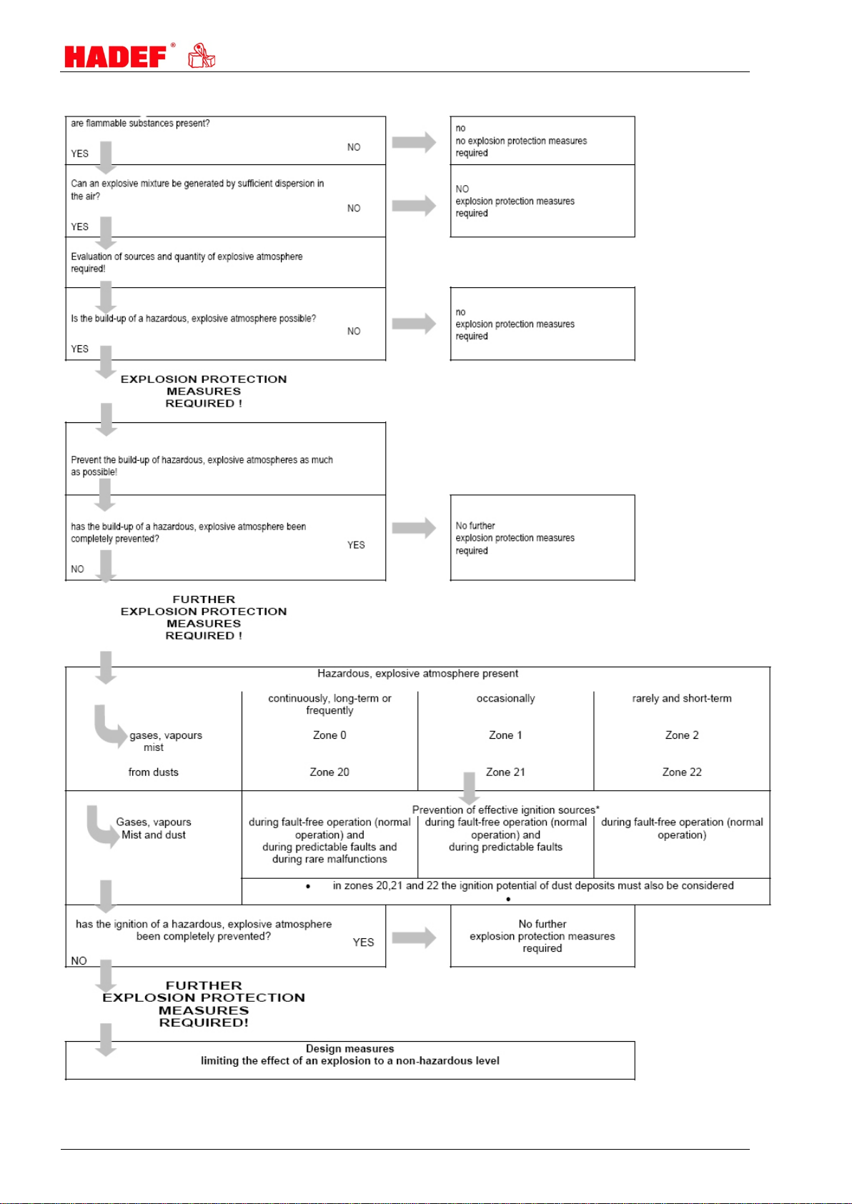
Lifting equipment for use in areas prone to explosion complies with current legislation, standards and
regulations and is classified in the applicable Ex-protection class.
The stated performance of the devices and meeting any warranty claims require adherence to all instructions
in this manual.
Before delivery, all products are packed properly. Check the goods after receipt for any damage caused
during transport. Report any damage immediately to the forwarding agent.
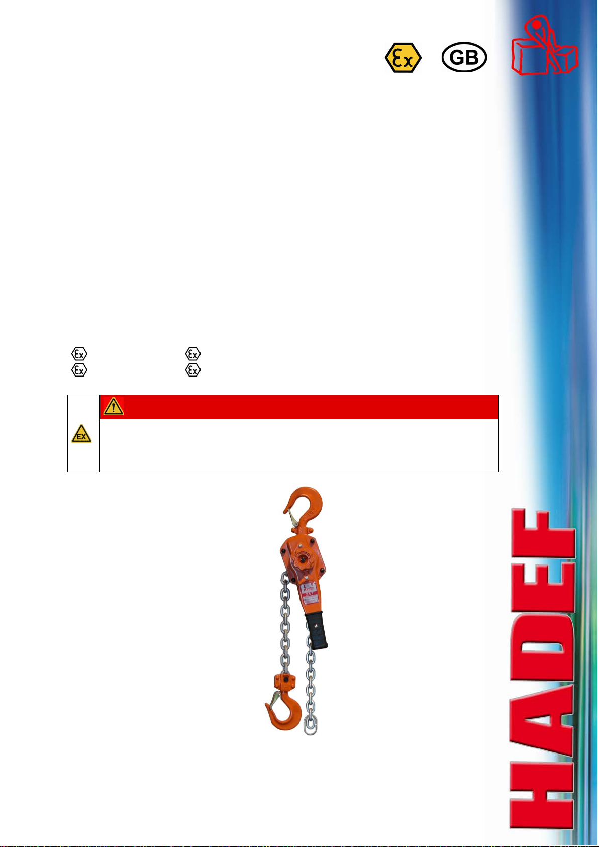
This manual serves for safe and efficient use of this hoist. Illustrations serve to explain something and may
differ from the illustration of the existing unit as they only serve as an example.
Documentation of component manufacturers that may be supplied additionally, must be observed, in case of
differences between these documentation and our manuals, the specification of the our manual must be
observed.
NOTICE!
We refer to the prescribed equipment tests before initial start-up, before putting back into operation and the
regular periodic inspections.
In other countries any additional national regulations must be observed.

4
5.52.185.01.01.02
2 Safety
DANGER!
To assess the intended use of the devices correctly, the user must carry out an Ex-zone
classification.
The classification must be carried out in accordance with all current legislation, standards and
regulations for areas prone to explosion!
2.1 Warning notice and symbols
Warnings and notice are shown as follows in these instructions:
DANGER!
This means that there is a high risk that leads, if it is not avoided, to death or severe injury.
WARNING!
This means that there is a risk that could lead, if it is not avoided, to death or severe injury.
CAUTION!
This means that there is little risk that could lead, if it is not avoided, to slight injury or damage to the device or its
surrounding.
NOTICE!
Gives advice for use and other useful information.
Danger from electricity.
Danger from explosive area.
2.2 Duty of care of the owner
DANGER!
Failure to follow the instructions of this manual can lead to unpredictable hazards.
For any resulting damage or personal injury, HADEF assumes no liability.
The unit was designed and built following a risk analysis and careful selection of the harmonized standards
that are to be complied with, as well as other technical specifications. It therefore represents state-of-the-art
technology and provides the highest degree of safety.
Our delivery includes the hoist supplied beginning at its suspension and ending at the load hook and if
supplied with control, the control line/hose that leads to the hoist. Further operating material, tools, load
attaching devices as well as main energy supply lines must be assembled according to the valid rules and
regulations. For explosion-proof equipment, all these parts must be approved for use in area prone to
explosion, or they must be suitable for use in area prone to explosion. The owner is responsible for this.
However, in everyday operation this degree of safety can only be achieved if all measures required are
taken. It falls within the duty of care of the owner/user of the devices to plan these measures and to check
that they are being complied with.
Complete the operating and installation instructions by any instructions (regarding supervision or
notifications)that are important for the special kind of use of the equipment, i.e. regarding organization of
work, work flow and human resources.
In particular, the owner/user must ensure that:
The unit is only used appropriately.
The device is only operated in a fault-free, fully functional condition, and the safety components, in
particular, are checked regularly to ensure that it is functioning properly.
The required personal protective equipment for the operators, service and repair personnel is available
and is used.
The operating instructions are always available at the location where the equipment is used and that they
are legible and complete.
The unit is only operated, serviced and repaired by qualified and authorized personnel.
This personnel is regularly trained in all applicable matters regarding safety at work and environmental
protection, and that they are familiar with the operating manual and, in particular, the safety instructions it
contains.
Any safety and warning signs on the devices are not removed and remain legible.

5.52.185.01.01.02
5
Devices for use in area prone to explosion must (from customer's side) be earthed with a shunting
resistor of < 106Ω against earth.
WARNING!
It is not allowed to make constructive changes of the equipment!
2.3 Requirements for the operating personnel
The units may only be operated by qualified persons that are appropriately trained and that are familiar with
it. They must have their employer’s authorization for operation of the units.
Before starting work, the operating personnel must have read the operating and installation instructions,
especially the chapter "Safety Instructions".
This is especially important for operating personnel that rarely uses the equipment, i.e. for installation or
maintenance work.
DANGER!
In order to avoid severe injury, please pay attention to the following when using the equipment:
Use protective clothes/equipment.
Do not wear long hair hanging down open.
Do not wear rings or other jewelry.
Do not wear clothes that are too big/wide.
Do not reach into ropes, chains, drive parts or other moving parts with your hands
2.4 Appropriate use
The permitted safe working load of the devices must not be exceeded! An exception can be made during the
load test before initial operation, carried out by a licensed qualified person.
The permissible ambient temperature during operation of manual driven devices is -20 ° C / + 50 ° C and
at all power driven devices -20 ° C / + 40 ° C!
Defective devices and load suspension devices must not be used until they have been repaired! Only
original spare parts must be used. Non-compliance will result in any warranty claims becoming void.
Liability and warranty will become void if unauthorized modifications of the units are made by the user!
The appropriate use of the hoists is vertical lifting and lowering of unguided loads. In combination with
trolleys, loads can also be moved horizontally.
DANGER!
It is not allowed:
pulling loose of stuck loads, dragging of loads and inclined pulling is not allowed.
in explosive atmosphere, except the unit is especially modified for it and marked by an indication label
In reactor containment vessels.
to transport people
The device is not suitable for use on stages and in studios
persons must not stand under a suspended load
NOTICE!
If the units are not used appropriately, it is not possible to ensure safe operation.
The owner and operator have sole liability for all personal injury and damage to property arising from
inappropriate use.
DANGER!
It’s only allowed to use the unit in the EX-classification which is named on the type plate; or in lower
classes
EX II 2G IIB c T4 or EX II 2D c 135°C
or
EX II 2G IIB c T3 or EX II 2D c 200°C

6
5.52.185.01.01.02
2.5 Basic safety measures
Observe installation-, operation and maintenance instruction.
Take notice of caution notes at units and in the manual
Observe safety distances.
Take care for a free view on the load.
Only use the hoists appropriately.
The equipment is to be used exclusively for movement of goods. Under no circumstances my persons be
moved.
Never load the devices beyond their working load limit.
Pay attention to the accident prevention regulations (UVV).
Should the hoist be used outside of Germany, please pay attention to the national regulations that apply.
Supporting structures and load-attached devices used in conjunction with this equipment must provide an
adequate safety factor to handle the rated load plus the weight of the equipment. In case of doubt, consult
a structural engineer.
If the equipment has not been used for a period of time, carry out visual checks of all main components
such as chains, load hooks etc. and replace any damaged parts with new, original spare parts before
putting the equipment back into operation!
Do not use a hoist that is defective, pay attention to any abnormal noise it makes during operation.
Stop working immediately in case of disturbances and remedy failures.
Any damage and faults must be reported to a responsible supervisor immediately.
If the unit is put into motion, any persons in the immediate vicinity must be informed by calling to them!
Please pay attention to the regulations for load carrying devices UVV for both positive and non-positive
methods of attaching loads.
The lifting tackle or the load must be securely attached to the hook and be seated at the bottom of the
hook.
The safety catch of hooks must be closed.
When charged, the housing may not be in contact somewhere.
Stop lowering the load when the bottom block or the load is being set down or is prevented from being
lowered further.
The load chain must not be twisted.
Twisted chains must be aligned before attaching the load.
The correct alignment of the chain links can be seen from the weld seams.
The chain links must always be aligned in one direction.
Don't bump against something with load or hook
Illustration 1
Motor drive is prohibited.
We recommend a unit with sliding clutch to prevent overload, when the unit is used for tightening,
WARNING!
The following is not allowed:
to lift another load than the nominal safe working load
to manipulate the sliding clutch if units are equipped with
The use of elongated or damaged chains or wire ropes. Replace them immediately by new, original
parts.
Never loop the load chain around a load nor place or pull the chain over edges.
Never repair damaged load hooks (e.g. by hammering), but replace them by original hooks.
DANGER!
Special safety measures for use in areas prone to explosion.
Not to be used with IIC gases and IIB gases hydrogen sulphide, ethylene oxide and light metal and shock
sensitive dusts!
No use in temperature class T5 or T6.

5.52.185.01.01.02
7
It is not allowed to use the equipment in area at risk from explosion where gas AND dust does both exist
at the same time!
During assembly and operation of explosion-proof equipment, the relevant regulations of i.e. BG-Chemie
about the use of equipment in area at risk from explosion, must be adhered to by the user/owner.
Please make sure that external ventilation is sufficient.
Please wear conductive shoes. Gloves should have a shunt resistance of < 108Ω.
It is not allowed to take off clothes.
The surface temperature of the devices could increase by a variety of external circumstances. For this
reason, the surface temperature is to be monitored.
Avoid ignitable dust deposits.
Remove dust deposits daily before commencing work and ensure that dust cannot settle between moving
parts.
Never remove dust with compressed air - remove it with a wet bolt of cloth.
Defective units or units that show abrasion of its surface rust on chains, hooks, or suspension devices,
must be taken out of service.
Please observe the prescribed intervals.
Assembly and maintenance work must only be carried out in an atmosphere not prone to explosion.
Check the grease level of the bearings regularly
Exchange friction surfaces in time and (an exception to this are electric units - maintenance of the brakes
must only be effected by HADEF).
Protect the device from impact, friction, rough handling and moisture.
Special scope
Use of different EX-zones is depended from the EX-classification of the unit. Find the EX-classification on its
type plate.
Unit classified
in EX-classification
No use
in EX-zone
3G/D
0,20,1,21
2G/D
0,20
3G
0,20,1,21,22
3D
0,20,1,21,2
2G
0,20,21,22
2D
0,20,1,2
2.6 Explosion protection
The EX classification of the unit is indicated on a
separate plate, situated on the unit.
Illustration 2

8
5.52.185.01.01.02
Example of ATEX classification:
II
2
G
IIB
c
T4
CE-marking European Union
explosion-proof operating
material
II
device group / application
I
II
danger of mine damp
other areas prone to explosion
2device category
1
2
3
Use in zone 0
Use in zone 1
Use in zone 2
G
EX atmosphere
G
D
....caused by gas, steam, fog
...caused by dust
IIB explosion group
IIA
IIB
IIC
limit gap widths (MESG) > 0,9 mm
limit gap widths (MESG) 0,9 >= 0,5 mm
limit gap widths (MESG) < 0,5 mm
c
type of protection
c
k
construction safety
encapsulation of liquids
T4 Temperature class - gas-
es
(for dust only the temper-
ature in °C is stated)
T1
T2
T3
T4
T5
T6
limit temperature 450 °C
limit temperature 300 °C
limit temperature 200 °C
limit temperature 135 °C
limit temperature 100 °C
limit temperature 85 °C
2.6.1 EX-Category
EX- Zone
1+21
2+22
1+21
2+22
Device category
2
2
Expl.-group of gases
IIB
IIB
Temperature class - gases
Temperature class - dust
T4
135°C
T3
200°C
DANGER!
The classification for the device can be found on the EX-type plate on the unit.
The device must only be used in the classification stated or in a lower classification.
2.6.2 Surface temperature of the devices
DANGER!
The temperature class mentioned on the EX-type plate on the unit must be observed, - make sure
that the max. surface temperature is even fallen short of.
DANGER!
The maximum surface temperature of the equipment must always be lower than the ignition
temperature of the gas/vapour/dust/air mixture. Equipment which has been classified in higher
temperature classes is, of course, also approved for use in applications with lower temperature
classes. As gas/air mixtures for T5 do not occur with normal use, and only very rarely occur for T6,
for specific gas/air mixtures such as carbon disulphide (IIC), our hoists are not rated for these
temperature classes and must not be used for these classes.

5.52.185.01.01.02
9
Temperature
class Ignition tem-
perature of gas
°C
max. surface
temperature of the
operating material in
°C
T1
>450
450
T2
>300 <450
300
T3
>200 <300
200
T4
>135 <200
135
T5
>100 <135
100
T6
>85 <100
85
2.6.3 EX zone classification
Areas that are prone to explosion are classified into zones. The owner must determine the zone that exists.
Information on the zone classification can be found in IEC 60079-10 and in national standards. The following
table contains an overview of the zone classification in combination with the device category.
Gases
Vapours
Mist
device category
(Gases) Dust device category
(dust)
explosive
atmosphere
is present
Zone 0 1G Zone 20 1D
continuously, long-term or
frequently
Zone 1
2G
Zone 21
2D
occasionally
Zone 2
3G
Zone 22
3D
rarely or short-term

10
5.52.185.01.01.02
2.6.4 Explosion hazards … recognizing and preventing!

5.52.185.01.01.02
11
3 Transport and Storage
CAUTION!
Transport may only be done by qualified personnel. No liability for any damage resulting from improper
transport or improper storage.
3.1 Transport
The devices are checked and if so adequately packed before delivery.
Do not throw or drop the equipment.
Use adequate means of transport.
Transport and means of transport must be suitable for the local conditions.
3.2 Safety device for transport
NOTICE!
Should a safety device for transport exist, please remove it before commissioning.
3.3 Storage
Store the equipment at a clean and dry place.
Protect the equipment against dirt, humidity and damage by an appropriate cover.
Protect hooks, wire ropes, chains and brakes against corrosion.
DANGER!
Units that show corrosion must be taken out of service!
4 Description
4.1 Areas of application
The devices must be as far as possible installed in a covered room.
If they are used in the open, protect the units against the effects of weather such as rain, hail, snow, direct
sunshine, dust, etc. - we recommend to use a cover in parking position. If the device is set up in a
continuously humid environment with strong temperature fluctuations, the correct functionings are
endangered by the forming of condensation.
Ambient temperature -20°C up to +50°C. Power-operated units -20 up to +40°C. Humidity 100 % or less but
not under water
Depending on the type of device, it is suitable for use in area at risk from explosion in the EX-classification
stated.
The EX-classification is mentioned on the EX-type plate on the hoist. The use of the unit is only allowed for
the EX-classification mentioned on the EX-type plate or lower EX classification.
4.2 Design
HADEF ratchet lever hoists are compact hoists
with suspension hook for stationary use.
Illustration 3

12
5.52.185.01.01.02
4.3 Functions
The load is lifted, lowered or tensioned by operating the lever. The load pressure brake prevents automatic
lowering of the load.
NOTICE!
If used "overhead" or "lashing" undefined forces may appear. We recommend to use a hoist with
slipping clutch for these cases.
NOTICE!
The best protection against functional failures in case of extreme environmental impact is the regular use of
the equipment.
4.4 Important components
Gear
Gear components are made of high-quality material.
Load pressure brake
Holds the load in any position.
A new brake system is used for the hoists (except
for the Aluminium Ratchet Lever Hoists). Brake
discs have sintered brake linings which are
designed for the lifetime of the devices when used
as intended.
According to DIN 13157 lifetime is 1500 operating
cycles (lifting/lowering movements) with 300 mm
lift with nominal load.
Illustration 4
Housing
Depending on the model made from steel plate or aluminium.
Load chain
According to EN 818-7-T high quality chain. All components match precisely to each other. Therefore please
only use original chains.
Load hook with safety catch
Forged steel. Rotating, this facilitates attaching the load and avoids twisting of the chain.
Ship hook with safety catch – as option
Ratchet Lever Hoists of capacity 1600 kg and 3200 kg can be fitted with ship hook - as option
The hook tip may only be loaded for tightening.
For lift and lower use, the load must lie on
on the hook base and the hook safety catch
must be closed.
Bild 5
DANGER!
In hazardous area, the load on the hook tip is prohibited!
Free-wheeling of chain
For pulling through of the uncharged chain.
Overload protection
Hoists with overload protection protect the hoist by a slipping clutch from damage by overload. When the
slipping clutch operates, lifting of the load is stopped. Lifting is only possible again after the load has been
lowered and reduced to nominal load.
Special Parts
For use in explosion dangerous areas, are be installed some special units, special treated surfaces or made
in special material.

5.52.185.01.01.02
13
5 Technical data
Capacity 800 kg 1 t 1,6 t 2,5 t 3,2 t 6,3 t 9 t
Number of chain falls 1 1 1 1 1 2 3
Load chain dimensions
mm
5,6x15,8
5,6x15,8
7,1x20,1
9,0x24,8
10x28,1
10x28,1
10x28,1
low headroom dimension
mm
280
300
335
375
395
540
680
lever force approx.
N
290
360
340
370
370
380
390
weight* approx.
kg
5,7
5,9
8,0
11,2
15,0
26,0
40,0
weight per add. m lift approx.
kg
0,7
0,7
1,1
1,7
2,3
4,7
7,0
5.1 Main dimensions
Dimensions
mm
800 kg 1 t 1,6 t 2,5 t 3,2 t 6,3 t 9 t
A
119
119
126
150
159
217
304
B
144
144
159
173
190
190
190
C
35,5
42,5
42,5
47
50
60
85
D
245
245
265
265
415
415
415
E
97
97
100
102
112
112
112
F
14
15
19
21
24,5
34
41,5
G
26,5
29
32
36,5
39
50
72,5
H
280
300
335
375
395
540
680
Illustration 6
6 Installation
Please observe the following points in order to avoid any damage to equipment or injury of person:
Please read chapter "Safety".
Before loading the hoist make sure the hooks are placed safely. The safety catch of the hook must be
closed.
Make sure that the fastening position cannot be changed either by the load nor by other influences.
6.1 Tools
7 Operation
Only people that are familiar with the operation of the lifting devices and cranes may be entrusted with their
operation. They must be authorized by the employer for the operation of the equipment. The employer must
ensure that the operating instructions are available near the equipment and that they are accessible for the
operating personnel.
7.1 Devices from 800 kg up to 9000 kg
Before start up please make sure the free-wheeling mechanism is deactivated.
Forcible pulling may possibly close the brake and stop the chain. Should this be the case place the switching
pin in position "▼", do some lowering operation movements and begin lifting again.
Lifting or pulling
Turn the switching pin in position (1) lifting or
pulling as marked on the type plate and move the
load by operating the hand lever.
Lowering or relieving
Turn the switching pin in position (2) lowering or
relieving and move the load by operating the hand
lever.
Illustration 7
7.1.1 Free-wheeling of chain
When the unit is used appropriately, unintended activation of the free-wheeling mechanism under load is
impossible. Opening of the brake system with only small load is possible, this is no mistake.

14
5.52.185.01.01.02
DANGER!
Never activate the free-wheeling mechanism if the hoist is under charge.
Switching ON the free-wheeling mechanism
Place the switch knob in middle position.
Illustration 8
Pull the free-wheeling wheel upwards in
direction ▲ .
The chain can be pulled through in both
directions.
A free-wheeling OFF
B free-wheeling switched ON
Illustration 9
Switching OFF the free-wheeling mechanism
Turn the free-wheeling wheel with one hand in
direction ◄ and pull the load chain at the same
time.
Free-wheeling wheel turns back to position
OFF.
Free-wheeling mechanism is switched OFF
C Switch OFF the free-wheeling.
D free-wheeling OFF
Illustration 10
7.2 Brake and pawl
The brake system needs a minimum load of 3% of the capacity.
Only this minimum load makes sure that the load-pressure-brake closes correctly. When the brake closes
correctly, the load is safely held.
DANGER!
Working situations with no guarantee that the minimum load is charged, are forbidden!
The brake remains closed (stuck) if:
The ratchet lever hoist is uncharged without lowering the load, i.e. in case of vertical lifting/lowering or in
case of horizontal pulling/tensioning.
The load hook is pulled against the housing and got stuck there.
The chain does not move, the load cannot be lowered.
Remedy:
Charge the ratchet lever hoist again
Release the brake by setting down the load.
OR: Turn the switching pin to position "Lowering" and release the hand lever with a strong jerk in direction
"▼".

5.52.185.01.01.02
15
8 Commissioning
8.1 General
Should the unit be used in Germany:
Please observe the validated, national accident prevention regulations.
For other countries:
Inspections as above. Please observe the national rules and regulations and the instructions in this manual!
NOTICE!
Hoists up to 1000 kg capacity and without motor-driven trolleys of hoisting unit must be tested by a “qualified
person” before putting into operation for the first time.
Hoists of 1000 kg capacity and up or with more than one motor-driven hoist movement; i.e. lifting and trolley
movement, must be tested by a “licensed qualified person” before putting in operation.
An exception is “hoists ready for operation” acc. validated national regulations with EU-declaration of
conformity.
Definition “qualified person” (former expert)
A “qualified person” has learned, due to occupational training and experience and the job that the person has
done, the skills needed to tests the material for one’s work.
Definition “licensed qualified person” (former approved expert)
A “licensed qualified person” has, due through special occupational training, knowledge about testing of the
material for one’s work and knows the national accident prevention regulations and other prescriptions and
technical regulations. This person must test the material for one’s work regularly with regard to design and
kind of use. The license will be given to qualified person be the approved supervision authorities (ZÜS).
8.2 Load chain
Before commissioning the load chain must be aligned and oiled.
For the first commissioning of motorized hoists, chain oil is supplied with the delivery.
Move safety note and fixing wire away from the chain.
CAUTION!
Do not use grease for lubrication of load chain.
Without lubrication, manufacturer's warranty and/or liability will be void.
NOTICE!
Continuous, thorough lubrication will increase the life of the chain considerably.
9 Safety check
Before putting into service initially or when putting back into service, it must be checked whether:
All fastening screws (if existent), socket pins, flap socket and safety devices are tightened and secured.
The chains are correctly placed, oiled and in good condition.
10 Maintenance
10.1 General
All monitoring, servicing and maintenance operations are to ensure correct functioning of the equipment;
they must be effected with utmost care.
Only “qualified persons” may do this work.
Servicing and maintenance work must only be done when the hoist is not loaded.
Records must be kept of all test results and measures taken.

16
5.52.185.01.01.02
10.2 Monitoring
The monitoring and servicing intervals stated are valid for operation under normal conditions and single-shift
operation. In case of severe operating conditions (e.g. frequent operation with full load) or special
environmental conditions (e.g., heat, dust, etc.), the intervals must be shortened correspondingly
10.3 Replacing the load chain
CAUTION!
If there is any visible damage and when the conditions for replacement are reached (i.e. one or several
dimensions in the table have been reached, there is corrosion or elongation), the chain must be replaced.
When replacing the chain, also check the chain wheels.
Procedure:
Only insert new chains in an unloaded state and as the chains that are currently in the device – i.e. not
twisted.
Remove chain from its fastening at the end and attach a chain link which is open at the side.
A chain link which is open at the side, can
easily be produced by grinding out a small
piece. The opening must have the same
thickness as the chain link.
Illustration 11
Hang a new original chain (same size and oiled) in the side opened chain link and insert it.
Make sure the chain is not installed twisted.
Make sure the chain links are aligned in one direction.
Assemble the chain to the end fastening.
11 Inspection
11.1 Periodic checks
Independently from the regulations of the individual countries, lifting devices must be checked at least yearly
by a qualified person or licensed qualified person regarding its functional safety.
11.1.1 Components to be checked
The following must be checked:
Dimensions of load chain, load hooks, pawls, bolts, ratchet wheels, brake linings.
The dimensions must be compared to the dimensions in the tables.
A visual inspection for deformations, cracks and corrosion must be carried out.
CAUTION!
When the wear limit is reached, the part must be exchanged by a new, original part.

5.52.185.01.01.02
17
at
commissioning
daily
checks
1st maintenance
after
3 months
Inspection
Maintenance
every
3 months
Inspection Mainte-
nance
every
12 months
Check screw connections
X
X
Check lifting, lowering functions.
X
X
Check brake function
X
X
for ratchet lever hoists: Check free-wheeling mechanism of the
chain
X X
Brake - check wear of brake lining
X
Check chain wheels, ratchet wheels and pawls.
X
Clean and lubricate the load chain.
X
X
X
Check the load chain for elongation and wear
X
Check the load hook for cracks and deformation
X
Load hook - check the safety catch
X
X
Check and lubricate the bearing of the chain pulleys.
X
X
Check the chain pulleys
X
X
Have the equipment checked by a qualified person
(periodic inspection)
X
Clean off of dust (don’t use compressed air)
X
Check of corrosion
X
X
Surface coated – wear control for
Load chain, hand chain, hook, housing
X X
Check grease - bearings
X
X
Check grease – pinion of trolleys *
X
X
Name plates – exist, check readability
X
Protection earthing – check (pneumatich equipment) *
X
X
*if applicable
WARNING!
If one or several of the dimensions fall below or exceed the dimensions in the table, or if cracks or
corrosion are found, the parts must be replaced with original spare parts.
11.2 Checking the load chain
CAUTION!
The load chain must be tested over its entire length!
The measure of the load chain must be carried out especially in the areas which are subject to the highest
wear. Through the lifting movement, these are the contact points of the chain with sprocket wheel and
deflection pulleys.
acc. DIN 685-part 5
L11 = pitch increase over 11 chain links
L1 = pitch increase over 1 chain link
Illustration 12
dm= detected link diameter (d1+d2)/2
Illustration 13
Chain dimensions
Table 1
Dimensions
mm
Chain size
3x9 4x12 4,2x12,2 5x15 5,6x15,8 5,6x17 6x18 6,3x19,1 7,1x20,1
L11
105,6
136,6
138,2
170,6
179,1
194,2
203,9
216,4
227,9
L1
9,9
12,7
12,8
15,7
16,6
18
18,9
20
21,2
dm
2,7
3,6
3,8
21,2
5,0
5,0
5,4
5,7
6,4
Table 2
Dimensions
mm
Chain size
7,1x21
7,9x23
8x24
9x24,8
9x27
10x28,1
10x30
13x36
16x45
L11
238,5
260,6
272,1
281,2
300,8
318,6
340,7
408,3
505,6
L1
22,3
24,1
25,3
26,1
28,1
29,6
31,8
37,9
47,4
dm
6,4
7,1
7,2
8,1
8,2
9,0
9,0
11,9
14,4
WARNING!
When the dimensions listed in the table are reached due to wear or deformation, the chain must be
replaced!

18
5.52.185.01.01.02
DANGER!
In case of corrosion and/or wear of the surface coating, the chains must be exchanged by original
chains.
11.3 Checking the load hook
Load hook
X = measuring distance hook mouth width
Y = measured length from hook no. 6
H = thickness of hook saddle
Illustration 14
Dimension
mm Capacity/chain falls
0,8 t 1 t 1,6 t 2,5 t 3,2 t 6,3 t 9 t
X or Y
26,5/41,5
31,5/49,4
35,5/52
41/58,6
43/61,9
53/84,3
64/-
H
20
22
26,5
29
31,2
45,5
60,4
Please fill in the measured
values before commissioning:
Capacity
t
X or Y
mm
H
mm
CAUTION!
When the dimension of hook opening width is deformed more than 10% or when the dimension of the hook
bottom thickness is fallen short of by 5% due to wear, the hook must be replaced.
DANGER!
In case of corrosion and/or wear of the surface coating, the hooks must be exchanged by original
hooks or the coating must be renewed.
11.4 Checking - pawl
A
Vmin
kg
mm
mm
800-1600
22
20,5
2500
29,2
27,7
3200-9000
31
29,5
11.5 Checking – Brake System
Ratchet wheel (A) with brake linings
D
Vmin
tn
tvmin
A
kg
mm
mm
mm
mm
800
64
61
8
6
1000
64
61
8
6
1600
64
61
8
6
2500
64
61
8
6
3200
74
71
8
6
6300
74
71
8
6
9000
74
71
8
6

5.52.185.01.01.02
19
11.6 Checking – Suspension and load hook bolt
Suspension bolt Load hook bolt
dn
dvmin
dn
dvmin
kg
mm
mm
mm
mm
800
12
11,1
7,5
6,9
1600
12
11,4
10,2
9,7
2500
14
13,3
11,5
11
3200
16
15,2
13
12,4
6300
16
15,2
13
12,4
9000
16
15,2
13
12,4
12 Service
12.1 Load chain
Wear at the links is mainly due to insufficient maintenance of the chain.
To ensure optimal lubrication of the links, the chain must be lubricated at regular intervals, depending on
usage.
Lubricate the chain with oil that creeps.
Always lubricate the chain when it is not under load so that the oil can wet the links affected by wear. It is
not sufficient to lubricate the chain from the outside, as this will not ensure the formation of a lubricating
film within the links. The adjacent link points must always be lubricated to prevent excessive wear.
If the same lifting operations are carried out constantly, the switching area from a lifting to a lowering
movement must be given special attention.
Thoroughly effected lubrication of the chain will prolong the life of the chain by approx. 20 times,
compared to dry run with unlubricated chain.
Wash dirty chain with petroleum or a similar cleaner, under no circumstances heat the chain.
If there are environmental influences that foster wear, such as sand, a dry lubricant should be used, e.g.
graphite powder.
When lubricating the chain’s condition of wear should be checked.
CAUTION!
Do not use grease for lubrication of load chain.
Without lubrication, manufacturer's warranty and/or liability will be void.
12.2 Pulleys
12.3 Load hook
Check bearings and pulleys yearly
Clean and lubricate the bearings of hooks and pulleys with grease
Slight bearings are maintenance free
When bearings resp. slight bearings are worn of, change the complete pulley
Use
Recommendation
Interval
Load chain
oil for example: FUCHS RENOLIN PG 220
or special chain lubricant
Use NO grease! 0,2 l 3 month
Use
Recommendation
Interval
Pulleys
FUCHS
RENOLIN PG220 Acc. to demand 12 month

20
5.52.185.01.01.02
12.4 Gear
Regular checks of lubrication are necessary. The teeth must be cleaned and re-lubricated after approx. 3
years. We recommend to use a lubricant of class EP2 or similar products. In case of severe conditions of
use (e.g. dust, regular lifting of the nominal load,etc.), please shorten maintenance intervals.
12.5 Gear spring pressure brake
During the check, brake lining wear is verified. The brake linings must be replaced when the wear limit is
already reached at one position of the lining, - as this can be the case when wear of the linings is irregular.
CAUTION!
The brake linings must be free from fracture. Avoid oil, grease, dirt and humidity on the brake linings as this
increases wear.
The brake lining for the ratchet lever hoist is tested for the whole product lifetime - under the precondition of
appropriate use - and must only be replaced in case of extraordinary wear.
NOTICE!
According to EN 13157 lifetime is 1500 operating cycles (lifting/lowering movements) with 300 mm lift with
nominal load and normal operation conditions.
Use by heavy conditions can shorten the product lifetime. In these cases, the thickness of the brake lining
must be checked more than 1x yearly. The ratchet wheel with the brake lining must be replaced when the
wear limit is reached or wear of the lining (one one side) is clearly visible.
12.6 Overload protection
DANGER!
The factory setting of the overload protection/slipping clutch is secured by sealing. In case of any changes
will void the warranty. Should maintenance be necessary, please contact a service company authorized by
the manufacturer.
12.7 Lubricant - Selection
FUCHS SHELL ESSO MOBIL TOTAL CASTROL KLÜBER
Renolit FEP 2 Alvania EP 2 Unirex EP 2 Mobilux EP 2 MULTIS EP2 -- --
Stabylan 5006 -- -- -- -- Optimol Viscoleb 1500 Klüberoil 4UH 1-1500
-- -- -- -- -- -- Wolfracoat 99113
Chain lubricant OKS 451
12.8 Lubricant for food industry – Selection (as option*)
SHELL
MOBIL
CASTROL
KLÜBER
Gearing
FM Grease HD2 Mobilgrease FM 222
--
Klüberoil 4UH 1-1500 N
Load chain
--
Lubricant FM 100
Optimol Viscoleb 1500
--
Load hook;
Pulleys
Gear rim;
Drive pinion
FM Grease HD2 Mobilgrease FM 222
-- --
* must be mentioned by order
Use
Recommendation
Interval
Load hook
bearing
FUCHS
RENOLIN PG220 Acc. to demand 12 month
Table of contents
Other HADEF Lifting System manuals
Popular Lifting System manuals by other brands

Presto Lifts
Presto Lifts PLS52-185 Installation, operation and service manual

RAM
RAM Trus-T-Lift Supplemental manual

babcopark
babcopark Starke 2127 user manual

Vestil
Vestil UNI owner's manual

Haklift
Haklift VAK3SUPER Translation of the original instructions

Draper
Draper AeroLift 25 Installation & operating instructions

Presto
Presto TT Series Installation, operation and service manual

HOMECARE PRODUCTS
HOMECARE PRODUCTS EZ-ACCESS TRIFOLD Advantage Series Instructions for use

AMGO Hydraulics
AMGO Hydraulics PRO-18 Installation and service manual

probst
probst VZ-II operating instructions

JLG
JLG 600SJ Service and maintenance manual

Vestil
Vestil AIR-1500-D instruction manual