Hafco EB-270DSA User manual

INSTRUCTION MANUAL
EB-270DSA
Swivel Head Metal Cutting
Band Saw (415V)
260 x 100mm (W x H) Rectangle
B066
1
Instruction Manual for EB-270DSA (B066)
31/03/2016

- 1 -
Contents
Chapter 1
ACCIDENT PREVENTION AND SAFETY
REGULATION
1.1 Advice for the operator 2
1.2 The electrical equipment according to European
Standard" CENELEC EN 60 204-1" (1992) 2
1.3 Emergencies according to European Standard
“CENELEC EN 60 204-1 (1992)” 2
Chapter 2
MACHINE DIMENSIONS TRANSPORT
INSTALLATION DISMANTLING
2.1 Machine dimensions 2
2.2 Assembling the control box to the saw 2
2.3 Machine Transportation 3
2.4 Minimum requirements for housing the machine 3
2.5 Anchoring the machine 3
2.6 Instructions for assembly of the loose parts and
accessories 3
2.7 Deactivation of machine 3
2.8 Dismantling 3
Chapter 3
THE MACHINE’S FUNCTIONAL PARTS
3.1 The saw arm 3
3.2 Controls 4
3.3 Vise adjustment 4
3.4 Cutting angle adjustment 5
3.5 The base 5
3.6 The operation cycle 5
Chapter 4
ADVICE ON USING YOUR BANDSAW
4.1 Recommendations and advice for using the
machine 6
Chapter 5
ADJUSTING YOUR MACHINE
5.1 Blade tension assembly 7
5.2 Adjusting the blade guide 7
5.3 Saw frame return stroke-limiting device 7
5.4 Changing the blade 8
5.5 Adjusting the blade to the flywheels 8
5.6 Replacing saw frame return spring 8
Chapter 6
ROUTINE AND SPECIAL MAINTENANCE
6.1 Daily maintenance 9
6.2 Weekly maintenance 9
6.3 Monthly maintenance 9
6.4 Six-monthly maintenance 9
6.5 Maintenance of other machine parts 9
6.6 Oils for lubricating coolant 9
6.7 Oil disposal 9
6.8 The gear box 9
6.9 Special maintenance 9
Chapter 7
TECHNICAL CHARACTERISTICS
7.1 Table of cutting capacity and technical details 9
Chapter 8
MATERIAL CLASSIFICATION AND CHOICE OF
TOOL
8.1 Definition of materials 10
8.2 Selecting blade 10
8.3 Teeth pitch 10
8.4 Cutting and advance speed 11
8.5 Blade running-in 11
8.6 Blade structure 11
8.7 Blade type 11
Chapter 9
NOISE TESTS 12
Chapter 10
WIRING DIAGRAM 13
Chapter 11
TROUBLESHOOTING
11.1 - Electrical components diagnosis 15
11.2 - Blade and cut diagnosis 17
Chapter 12
MACHINE COMPONETS
12.1 Parts list 21
12.2 Explosion drawings 24
2
Instruction Manual for EB-270DSA (B066)
31/03/2016

- 2 -
1ACCIDENT PREVENTION AND
SAFETY REGULATION
This machine has been designed to comply with
national and community accident-prevention
regulations. Improper use and/or tampering with the
safety devices will relieve the manufacturer of all
responsibility.
1.1 Advice for the operator
- Check that the voltage indicated on machine motor is
the same as the line voltage.
- Check the efficiency of your electric supply and
grounding system; connect the power cable of the
machine to the socket and the ground lead
(yellow-green in color) to the grounding system.
- When the saw frame is in suspended mode (or raised)
the blade must not move.
- Only the blade section used for cutting must be kept
unprotected. To remove guards operate on the
adjustable head.
- It is forbidden to use the machine without its shields
- Always disconnect the machine from the power
socket before blade change or carrying out any
maintenance job, even in the case of abnormal
machine operation.
- Always wear suitable eye protection.
- Never put your hands or arms into the cutting area
while the machine is operating.
- Do not shift the machine while it is cutting.
- Do not wear loose clothing like: shirts with sleeves
that are too long, gloves that are too big, bracelets,
chains or any other object that could get caught in the
machine during operation. Tie back long hair.
- Keep the area free of equipment, tools, or any other
object.
- Perform only one operation at a time. Never have
several objects in your hands at the same time.
Keep your hands as clean as possible.
- All internal operations, maintenance or repairs, must
be performed in a well-lit area or where there is
sufficient light from extra sources so as to avoid the
risk of even slight accidents
1.2 The electrical equipment according to
European Standard" CENELEC EN 60 204-1" which
assimilates, with some integrating modifications,
the publication "IEC 204-1 (1992)"
- The electrical equipment ensures protection against
electric shock as a result of direct or indirect contact.
The active parts of this equipment are housed in a
box to which access is limited by screws that can only
be removed with a special tool; the parts are fed with
alternating current as low voltage (24V). The
equipment is protected against splashes of water and
dust.
- Protection of the system against short circuits is
ensured by means of rapid fuses and grounding; in
the event of a motor overload, protection is provided
by a thermal probe.
- In the event of a power cut, the specific start-up
button must be reset.
- The machine has been tested in conformity with point
20 of EN 60204
1.3 Emergencies according to European Standard
“CENELEC EN 60 204-1 (1992)”
- In the event of incorrect operation or of danger
conditions, the machine may be stopped immediately
by pressing the red mushroom button.
- The casual or voluntary removal of the blade cover of
the flywheels causes the stepping-in of a interlock
switch that automatically stops all machine functions.
- In case blade breakage, the tension release
microswitch disconnects all machine functions.
NOTE: Resetting of machine operation after each
emergency stop requires specific restart button.
2 MACHINE DIMENSIONS
TRANSPORT INSTALLATION
DISMANTLING
2.1 Machine dimensions
2.2 Assembling the control box to the saw
- Attach the control box to the saw with two provided
set screws.
3
Instruction Manual for EB-270DSA (B066)
31/03/2016

- 3 -
2.3 Machine Transportation
If the machine needs to be moved in its own packing,
use a forklift truck or sling it with straps as illustrated.
2.4 Minimum requirements for housing the
machine
- Main voltage and frequency must comply with the
machine’s motor requirements.
- Environment temperature should fall within –10 ºC to
+50 ºC.
- Relative humidity cannot be over 90%.
2.5 Anchoring the machine
Position the machine on a firm cement floor,
maintaining, at the rear, a minimum distance of 800
mm from the wall; anchor it to the ground as shown in
the diagram, using screws and expansion plugs or tie
rods sunk In cement, ensuring that it is sitting level.
2.6 Instructions for assembly of the loose parts
and accessories
Fit the components supplied:
Detail 1 Mount bar-stop rod
Detail 2 Mount and align the roll-supporting arm as per
the counter-vise table.
2.7 Deactivation of machine
- If the sawing machine is to be out of use for a long
period, it is advisable to proceed as follows:
I) Detach the plug from the electric supply panel
2) Loosen blade
3) Release the arch return spring
4) Empty the coolant tank
5) Carefully clean and grease the machine
6) If necessary, cover the machine.
2.8 Dismantling (due to deterioration and/or
obsolescence)
General rules
If the machine is to be permanently demolished and/or
scrapped, divide the material to be disposed of
according to type and composition, as follows:
1) Cast iron or ferrous materials,composed of metal
alone, are secondary raw materials, so they may be
taken to an iron foundry for re-smelting after having
removed the contents (classified in point 3).
2) Electrical components, including the cable and
electronic material (magnetic cards, etc.), fall within the
category of material classified as being assimilated to
urban waste according to the laws of your local, state,
or federal government, so they may be set aside for
collection by the public waste disposal service;
3) Old mineral and synthetic and/or mixed oils,
emulsified oils and greases are considered hazardous
or special refuse, so they must be collected,
transported and disposed of at a special waste
disposal service.
NOTE: The standards and legislation concerning
refuse is in a constant state of evolution, therefore is
subject to changes. The user must keep informed of
the regulations at the time of disposal as these may
differ from those described above.
3 THE MACHINE’S FUNCTIONAL
PARTS
3.1 The saw arm
Machine part consisting of drive members (gear motor
or variable speed motor, flywheels), tension and
guides (blade guide slide, blade guide blocks) of blade.
4
Instruction Manual for EB-270DSA (B066)
31/03/2016

- 4 -
3.2 Controls
A~G Control Switches
A. Speed selector
B. Main connect switch
C. Saw bow up switch
D. Saw bow down switch
E. Hand/foot pedal operation selector
F. Cycle start switch
G. Start switch (hydraulic flow control)
H. Emergency button
I. Footpad emergency button
J. Footpad switch
K. Flow regulator
1~17 Indicator lights
Red- Warning indicator
Yellow- Selection indicator
Green- Operation indicator
1. Power supply ON, indicator lights
2. Saw bow up, indicator light
3. Saw bow down, indicator light
4. Hand operation, indicator light
5. Foot pedal operation, indicator light
6. Cycle start switch indicator light
7. Start switch (hydraulic flow control), indicator light
8. Saw bow maximum height, indicator light
9. Saw bow lowest height, indicator light
10. Open blade cover, warning indicator light
11. Improper speed selection, warning indicator light
12. Motor overload, warning indicator light
13. Broken blade, warning indicator light
14. Emergency button indicator light
15. Hydraulic motor overload, warning indicator light
16. Foot pad’s emergency button indicator light
17. Foot pad, operation indicator light
3.3 Vise adjustment
Clamping the Work Piece
- Place work piece between the jaws.
- Use the hand wheel to close the vise jaw. For
multiple cuts of a same size material, leave a small
gap between the work piece and vise jaw. Push cycle
start button (F). The vise will automatically clamp the
work piece while going through the operation cycle.
When the operation cycle is finished, the vise will open
and the work piece can be adjusted or replaced.
Operation of the Vise
When cutting angles, it may require the adjustment of
the vise jaw’s position so that the saw blade’s path is
not impeded. Follow the procedures below.
- Release the track support by turning handle (1)
counter-clockwise.
- Release the vise by moving the lever (2) to the left.
- The vise may now be moved to right position or left
position by pushing with one hand on the adjustable
vise jaw and the other hand on the track handle (1).
- Once in position, move the lever (2) to the right to
lock it into position. If the lever (2) is not between
the vise/bed mounts and facing the user, then the
vise will not be able to lock. If the vise lever (2) has
K
H
I
J
1
E
B
A
G
DC
1
2 3 5
7
4
6
F
16
17
14
13
15
10
8
9
12
11
5
Instruction Manual for EB-270DSA (B066)
31/03/2016

- 5 -
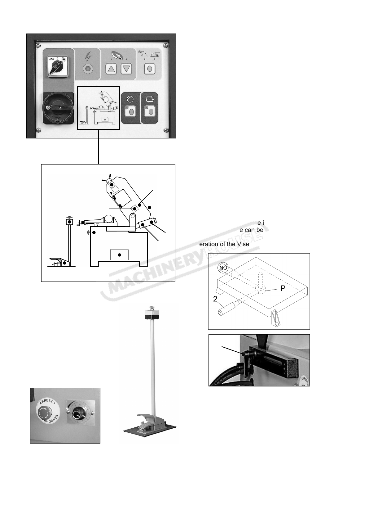
gone beyond or is obstructed by a vise/bed mount,
then use the following procedures.
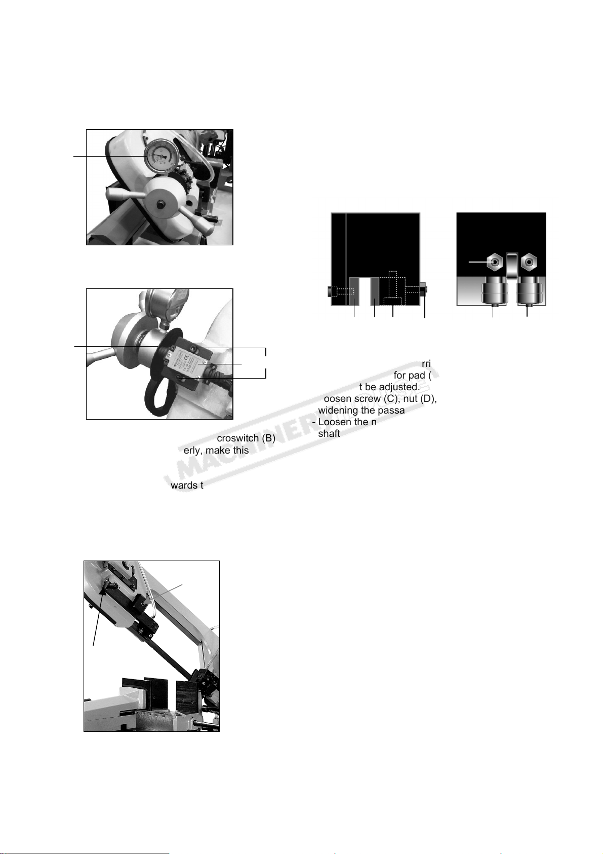
- Adjust the lever (2) by grasping at the pivot point (P)
and lowering it, which may assist in the adjustment.
The lever can now be freely rotated into a more
convenient position. Some movement of the vise
jaw may be required. Raise the lever (2) then move to
the right to lock.
- Lock the track support (1) by turning handle
clockwise.
3.4 Cutting angle adjustment
Cutting at angles
- Angle can be cut up to 60°.
- Unlock lever (L) by pushing it to the left side.
- Rotate the saw arm to the desired angle by
following the index on the scale.
- Lock lever (L) by pushing to the right side.
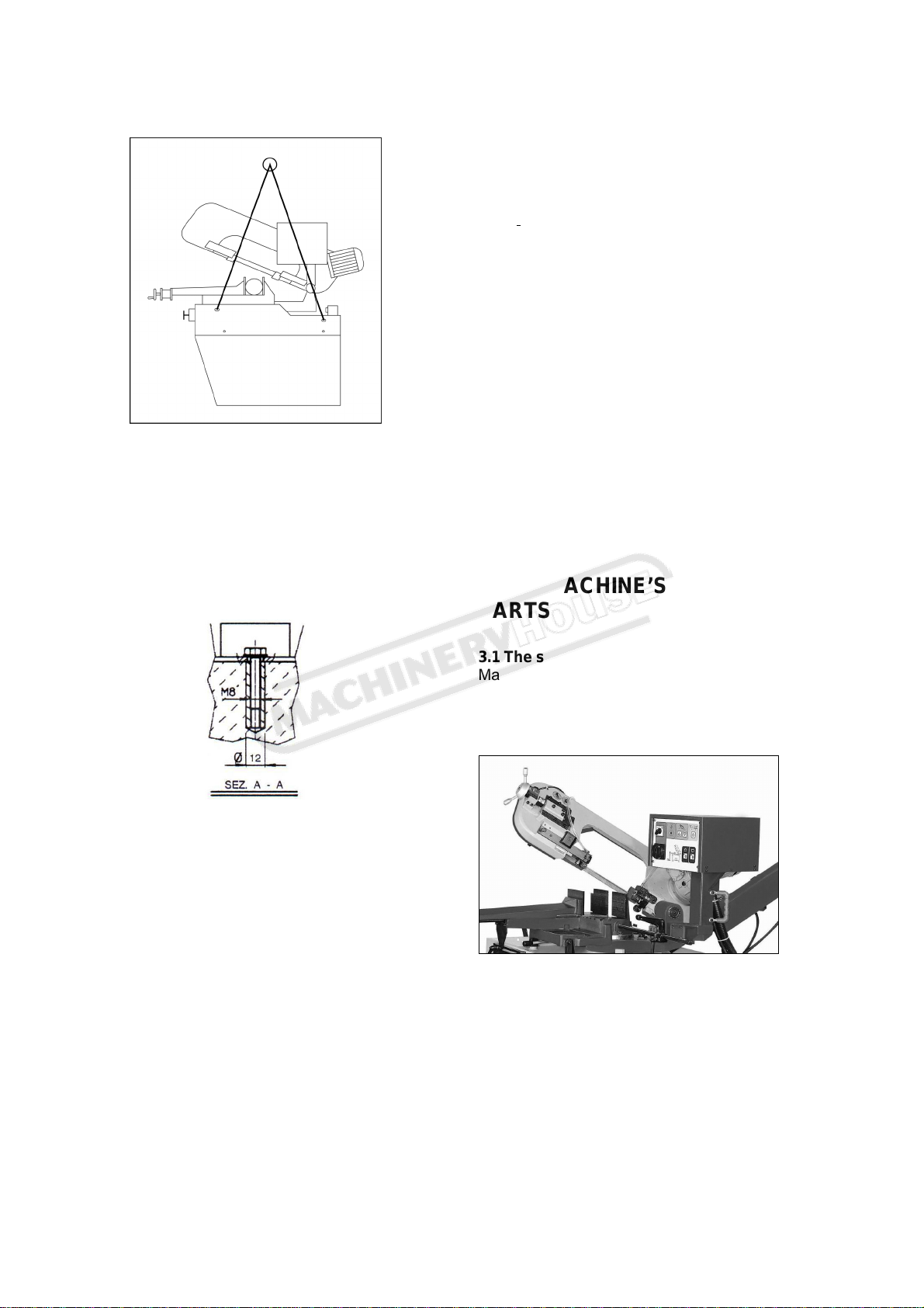
3.5 The base
- A structure supporting the SAW ARM (revolving arm
for gradual cutting and respective blocking system),
the VISE, the BAR STOP, the ROLLER for the support
of the material. The base houses the cooling liquid
TANK, PUMP, and the DEVICE CONTROLLING THE
AUTOMATIC HYDRAULIC LOWERING AND RISING
OF THE SAW FRAME.
The main connect switch is designed with a lock hole.
A lock can be attached to the lock hole to prevent
machine operation for safety and security purposes.
- To use the footpad switch (J), first use the side of the
foot to push aside the plastic clip that blocks the foot
pad. Be careful not to damage the clip by using
excessive force or stomping on the footpad. Next,
step down on the footpad to start operation.
3.6 The operation cycle
- Make sure the voltage indicated on machine motor is
the same as power source voltage. Connect the
machine to the power source, and Press the main
connect switch (B). If power indicator light (1) is on,
it means the voltages are okay.
-Select the cutting speed on switch (A).
*Note: While selecting the cutting speed indicator
light will blink.
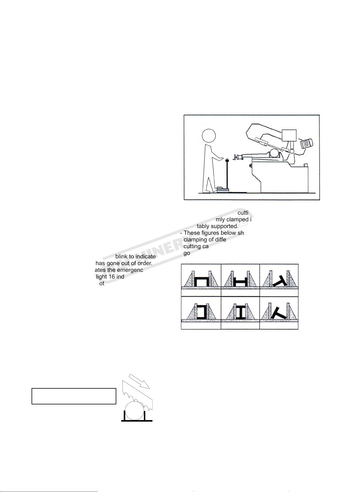
-Press hydraulic flow control start switch (G). *Note: If
the hydraulic flow control fails to activate, then switch
(C), (D), and (F) cannot operate. Indicator light (7)
will blink if any are pressed, indicating that start switch
(G) has failed to activate.
-Check the hydraulic oil level. If oil rises up, it means
the motor is running in the right direction. If not,
rewire the plug.
- Check that the saw arm is properly set. Press saw
bow switches (C) or (D) to adjust the bow height to
help when setting the workpiece.
-Place the workpiece in the vise and clamp securely.
-Select the speed using speed selector switch (A).
The turtle indicates low speed and the rabbit indicates
high speed. “O” is for neutral.
-Be sure to stand in a safe location while operating.
There are two ways to start the machine. Press the
switch (C) to let the saw bow return to the highest
position and then using the first method, select hand
operation on selector (E) and press cycle start switch
(F) to start operation. Using the second method,
Select footpad operation on selector (E) and step on
start footpad (J) to start operation.
- In general, start cuts by slightly turning hydraulic flow
regulation switch (K) counter-clockwise from 2 to 3 to
control the saw arm descent rate. If the arm
descends too quickly, turn hydraulic flow regulation
switch (K) clockwise all the way back to stop its
descent - When cutting different material use the
hydraulic flow regulation switch (K) to control saw
arm’s rate of descent.
*Note: A saw arm dropping too quickly can cause the
blade to stall on the work piece and the machine will
L
J
6
Instruction Manual for EB-270DSA (B066)
31/03/2016

- 6 -
BLADE CUTTING DIRECTION
shut off. If so, push down on either emergency push
buttons (I or H) to immediately stop all machine
functions.
- During the operation cycle, the hydraulic vise will
automatically close on the work piece for a distance
up to 8mm. The hydraulic vise will then open
maximum 8mm on end of operation. Now it is ready
for the next operation. Therefore, it is not necessary
to manually lock down the vise jaws on the work piece
for every operation. Allowing a gap of 4-5mm
between jaws and the work piece will suffice.
-The saw bow will return to the bow’s maximum height
upon completion of operation.
- In case of Emergency or problem during the
operation cycle, press the emergency push button (H
or I) down to shut off all functions.
-To release the emergency push button (H or I), rotate
the mushroom shaped button clock-wise. The button
will pop up and then the cutting cycle can be
restarted.
-The hydraulic flow control (G) will automatically
shut-off after 5 minutes of non-operation.
*Note: If the hydraulic flow control fails to activate, then
switch (C), (D), and (F) cannot operate. Indicator
light (7) will blink if any are pressed, indicating that
start switch (G) has failed to activate.
-If the hand operation is selected and the foot pad is
used, then the hand operation indicator light (4) will
blink. And vice versa, If the foot pad operation is
selected and the hand switches are used, then the
foot operation indicator light (5) will blink. They
indicate improper selection.
-The appropriate indicator light will blink to indicate
which part of the machine has gone out of order.
1. Indicator light 14 indicates the emergency button
is pressed. Indicator light 16 indicates the
emergency button on foot pad is pressed.
2. Indicator light 13 indicates the band saw blade
has broken.
3. Indicator light 10 indicates the blade cover is
open.
4. Indicator light 12 indicates the motor has
overloaded.
5. Indicator light 15 indicates the hydraulic motor
has overloaded.
6. Indicator light 11 indicates the speed is not
properly selected.
-If the saw bow up/down switches are out of order then
indicator lights 2 and 3 will blink at the same time.
4ADVICE ON USING YOUR
BANDSAW
4.1 Recommendations and advice for using the
machine
The machine has been designed to cut metal building
materials, with different shapes and profiles, used in
workshops, turner's shops and general mechanical
structural work.
Only one operator is needed to use the machine, that
must stand as shown in the picture.
- Before starting each cutting operation, ensure that
the part is firmly clamped in the vise and that the end
is suitably supported.
- These figures below show examples of suitable
clamping of different section bars, bearing in mind the
cutting capacities of the machine in order to achieve a
good efficiency and blade durability.
- Do not use blades of a different size from those
stated in the machine specifications.
- If the blade gets stuck in the cut, press the cycle start
switch or emergency button to switch off the machine.
Open the vise slowly, remove the part and check that
the blade or its teeth are not broken. If they are
broken, change the blade.
- Check saw frame return spring to ensure proper
balancing.
- Before carrying out any repairs on the machine,
consult the dealer.
7
Instruction Manual for EB-270DSA (B066)
31/03/2016

- 7 -
5ADJUSTING YOUR MACHINE
5.1 Blade tension assembly
The ideal tension of the blade is achieved rotating the
handwheel until the needle reaches the proper blade
tension on the tension gauge (A).
The machine will not operate if the microswitch does
not actuate by contacting the touch plate (C).
If the tension is set properly, but the microswitch (B)
does not contact or trigger properly, make this
adjustment.
-Loosen the setscrews (D).
-Push the microswitch (B) towards the touch plate (C).
Make sure that the plunger is pressed properly.
-Tighten down the setscrews (D) to secure the
microswitch (B) in place.
5.2 Adjusting the blade guide
- Disconnect the machine from the power source.
- Use a Hex. Wrench to loosen Hex. Socket screw (A)
on the square lock plate.
- Hold the handle (B) and slide blade guide block as
close as possible to the material without interfering
with the cut
- Tighten the hex. socket screw (A).
- Reconnect the machine to power source.
Blade guide blocks
The blade is guided by means of pads and bearings
that are set in place during inspection as per the
thickness of the blade with minimum play as shown in
the figure. In case the blade needs to be replaced,
make sure to always install 0.9mm thick blades for
which the blade guide pad and bearings have been
adjusted.
For saw blades with adifferent thickness, the
adjustment should be carried out as follows:
Note: the position for pad (A) and bearing (F) are fixed
and cannot be adjusted.
- Loosen screw (C), nut (D), and setscrew (D) to
widening the passage between the pads (A and B).
- Loosen the nut (G) and setscrew (G) and rotate the
shaft screw (E) with a flat head screwdriver to widen
the passage between the bearings (E and F).
- To mount the new blade: adjust the pad (B) to the
blade then loosen the setscrew to allow a play of 0.04
mm for the movement of the saw blade. Lock the
nut (D), screw (D), and screw (C), Rotate the shaft (E)
until the bearings rest against the blade as indicated
in the figure and then secure the setscrew (G) and
nut (G).
5.3 Saw frame return stroke-limiting device
It consists in a mechanical adjustment system,
mounted parallel to the saw frame rise cylinder, to
reduce the passive phases of the operating cycle. In
other words it eliminates the idle stroke that takes
place when the size of the part to be cut is much
smaller than the maximum cutting capacity. Practically,
you adjust the starting position of the blade in proximity
of the part, independently of its dimensions.
Operate as follows:
- Slightly open the flow regulation valve (H).
- Bring the blade as near as 10mm from the work piece
with the bow up/bow down switches (C and D).
- Loosen handle (7) to release the adjustable stop (8)
against the limit switch (9).
- Lock the handle (7)
ATTENTION:
- It is not necessary to adjust the mechanical stop (8)
every time; bring the blade near the workpiece by
B
A
A B C D E
G
F
A
B
C
D
8
Instruction Manual for EB-270DSA (B066)
31/03/2016

- 8 -
means of bow switch (D) and then start the automatic
cutting cycle (F), which will begin operation from this
position of the blade.
- The bow will return to the upper end stroke.
5.4 Changing the blade
To change the blade:
- Lift the saw arm.
- Loosen the blade with the hand wheel, remove the
mobile blade-guard cover, open the flywheel guards
and remove the old blade from the flywheels and the
blade guide blocks.
- Assemble the new blade by placing it first between
the pads and then on the race of the flywheels,
paying particular attention to the cutting direction of
the teeth.
- Tension the blade and make sure it perfectly fits
inside the seat of the flywheels.
- Assemble the mobile blade-guide end, the flywheel
guard, and fasten it with the relative knobs. Check
that the safety microswitch is activated otherwise
when electric connection will be restored the machine
will not start.
5.5 Adjusting the blade to the flywheels
1. Loosen the hex nut screws A, B, and C.
2. Use an Allen wrench on set screw D to adjust the
tilt of the flywheel.
-Turning the set screw D clockwise will tilt flywheel so
that the blade will ride closer to the flange.
-Turning the set screw D counter-clockwise with tilt the
flywheels that the blade will ride away from the flange.
If the blade rides away too far then it will come off.
After the adjustment is finished, fasten the hex nut
screws in this order: A, B, and C.
Checking the adjustment of the blade
Use a strip of scrap paper and slide it between the
blade and the flywheel while it is running.
-if the paper is cut then the blade is riding too close to
the flange. Re-adjust.
-if you notice that the blade is riding away from the
flange. Then re-adjust.
WARNING: Always assemble blades having
dimensions specified in this manual and for which the
blade guide heads have been set; otherwise, see
chapter on "Description of the operating cycle" in the
section Starting-up.
5.6 Replacing saw frame return spring
- When performing this operation it is necessary to
support saw arm using the lifting device.
- Replace the spring by loosening the upper coupling
rod and releasing it from the lower tie-rod.
6 ROUTINE AND SPECIAL
MAINTENANCE
THE MAINTENANCE JOBS ARE LISTED BELOW,
DIVIDED INTO DAILY, WEEKLY, MONTHLY AND
SIX-MONTHLY INTERVALS. IF THE FOLLOWING
OPERATIONS ARE NEGLECTED, THE RESULT
WILL BE PREMATURE WEAR OF THE MACHINE
AND POOR PERFORMANCE.
A Tilt in this direction will cause the
b
l
ade
to
ri
de
to
w
a
r
ds
t
h
e
fl
a
n
ge
A Tilt in this direction will cause the
b
l
ade
to
ri
de
a
w
ay
fr
o
m
t
h
e
fl
a
n
ge
Top view
Set screw D
paper
Blade direction
flywheel
TOP
A
C
B
Set screw D
9
Instruction Manual for EB-270DSA (B066)
31/03/2016

- 9 -
6.1 Daily maintenance
- General cleaning of the machine to remove
accumulated shavings.
- Clean the lubricating coolant drain hole to avoid
excess fluid.
- Top off the level of lubricating coolant.
- Check blade for wear.
- Rise of saw frame to top position and partial
slackening of the blade to avoid useless yield stress.
- Check functionality of the shields and emergency
stops.
6.2 Weekly maintenance
- Thorough cleaning of the machine to remove
shavings, especially from the lubricant fluid tank.
- Removal of pump from its housing, cleaning of the
suction filter and suction zone.
- Clean the filter of the pump suction head and the
suction area.
- Use compressed air to clean the blade guides (guide
bearings and drain hole of the lubricating cooling).
- Cleaning flywheel housings and blade sliding
surfaces on flywheels.
6.3 Monthly maintenance
- Check the tightening of the motor flywheel screws.
- Check that the blade guide bearings on the heads are
perfect running condition.
- Check the tightening of the screws of the gear motor,
pump, and accident protection guarding.
6.4 Six-monthly maintenance
- Continuity test of the equipotential protection circuit.
6.5 Maintenance of other machine parts
The worm drive gearbox mounted on the machine is
maintenance-free guaranteed by its manufacture.
6.6 Oils for lubricating coolant
Considering the vast range of products on the market,
the user can choose the one most suited to their own
requirements, using as reference the type SHELL
LUTEM OIL ECO. THE MINIMUM PERCENTAGE
OF OIL DILUTED IN WATER IS 8 - 10 %.
6.7 Oil disposal
The disposal of these products is controlled by strict
regulations. Please see the Chapter on "Machine
dimensions Transport - Installation" in the section
on Dismantling.
6.8 The gear box
The gear box requires periodic changing of oil. The
oil must be changed by the first 6 months of a new
machine and every year thereafter.
To change the gear box oil
- Disconnect the machine from the power source.
- Raise the saw arm to vertical position.
- Release the drain hold (O) to draw off gear oil by
loosening the hex socket screw (P).
- Replace the screw (P) after oil completely flows off.
- Place the saw arm back to horizontal position.
- Fill Gear box with approximately .3 liter of gear oil
through the hole of the vent screw (Q)
For reference, use SHELL type gear oil or Mobile gear
oil #90.
6.9 Special maintenance
Special maintenance must be conducted by skilled
personnel. We advise contacting your nearest dealer
and/or importer. Also the reset of protective and safety
equipment and devices (of the reducer), the motor, the
motor pump, and other electrical components requires
special maintenance.
7TECHNICAL CHARACTERISTICS
7.1 Table of cutting capacity and technical details
10
Instruction Manual for EB-270DSA (B066)
31/03/2016

- 10 -
8MATERIAL CLASSIFICATION AND
CHOICE OF TOOL
Since the aim is to obtain excellent cutting quality, the
various parameters such as hardness of the material,
shape and thickness, transverse cutting section of the
part to be cut, selection of the type of cutting blade,
cutting speed and control of saw frame lowering.
These specifications must therefore be harmoniously
combined in a single operating condition according to
practical considerations and common sense, so as to
achieve an optimum condition that does not require
countless operations to prepare the machine when
there are many variations in the job to be performed.
The various problems that crop up from time to time
will be solved more easily if the operator has a good
knowledge of these specifications.
8.1 Definition of materials
The table above lists the characteristics of the
materials to be cut. So as to choose the right tool to
use.
8.2 Selecting blade
First of all the pitch of the teeth must be chosen, in
other words, the number of teeth per inch (25,4 mm)
suitable for the material to be cut, according to these
criteria:
- Parts with a thin and/or variable section such as
profiles, pipes and plate, need close toothing, so that
the number of teeth used simultaneously in cutting is
from 3 to 6;
- Parts with large transverse sections and solid
sections need widely spaced toothing to allow for the
greater volume of the shavings and better tooth
penetration;
- Parts made of soft material or plastic (light alloys,
mild bronze, Teflon, wood, etc.) also require widely
spaced toothing;
- Pieces cut in bundles require combo tooth design.
8.3 Teeth pitch
As already stated, this depends on the following
factors:
-Hardness of the material
-Dimensions of the section
-Wall thickness.
11
Instruction Manual for EB-270DSA (B066)
31/03/2016

- 11 -
8.4 Cutting and advance speed
The cutting speed (m/min) and the advance speed
(cm2/min =area traveled by the disk teeth when
removing shavings) are limited by the development of
heat close to the tips of the teeth.
- The cutting speed is subordinate to the resistance of
the material (R = N/mm2), to its hardness (HRC) and
to the dimensions of the widest section.
- Too high an advance speed (= lowering of the saw
frame) tends to cause the disk to deviate from the
ideal cutting path, producing non rectilinear cuts on
bath the vertical and the horizontal plane.
The best combination of these two parameters can be
seen directly examining the chips.
Long spiral-shaped chips indicate ideal cutting.
Very fine or pulverized chips indicate lack of feed
and/or cutting pressure.
Thick and/or blue chips indicate overload of the blade.
8.5 Blade running-in
When cutting for the first time, it is good practice
to run in the tool making a series of cuts at a low
advance speed (= 30-35 cm2/min on material of
average dimensions with respect to the cutting
capacity and solid section of normal steel with R =
410-510 Nimm2). Generously spraying the cutting
area with lubricating coolant.
8.6 Blade structure
Bi-metal blades are the most commonly used. They
consist of a silicon-steel blade backing by a laser
welded high speed steel (HHS) cutting edge. The type
of stocks are classified in M2, M42, M51 and differ
from each other because of their major hardness due
to the increasing percentage of Cobalt (Cc) and
molybdenum (Mo) contained in the metal alloy
8.7 Blade type
They differ essentially in their constructive
characteristics, such as:
- Shape and cutting angle of tooth
-Pitch
- Set
Shape and angle of tooth
REGULAR TOOTH: Oº rake and constant pitch.
Most common form for transversal or inclined cutting of
solid small and average cross-sections or pipes, in
laminated mild steel and gray iron or general metal.
POSITIVE RAKE TOOTH: 9º - 10º positive rake and
constant pitch.
Particular use for crosswise or inclined cuts in solid
sections or large pipes, but above all harder materials
(highly alloyed and stainless steels, special bronze and
forge pig iron).
COMBO TOOTH: pitch varies between teeth and
consequently varying teeth size and varying gullet
depths. Pitch varies between teeth, which ensures a
smoother, quieter cut and longer blade life owing to the
lack of vibration.
Another advantage offered in the use of this type of
blade in the fact that with an only blade it is possible to
cut a wide range of different materials in size and type.
COMBO TOOTH: 9º - 10º positive rake.
This type of blade is the most suitable for the cutting of
section bars and large and thick pipes as well as for
the cutting of solid bars at maximum machine capacity.
Available pitches: 3-4/4-6.
SETS
Saw teeth bent out of the plane of the saw body,
resulting in a wide cut in the workpiece.
12
Instruction Manual for EB-270DSA (B066)
31/03/2016

- 12 -
REGULAR OR RAKER SET:Cutting teeth right and
left, alternated by a straight tooth.
Of general use for materials with dimensions superior
to 5 mm. Used for the cutting of steel, castings and
hard nonferrous materials.
WAVY SET:Set in smooth waves.
This set is associated with very fine teeth and it is
mainly used for the cutting of pipes and thin section
bars (from 1 to 3 mm).
ALTERNATE SET (IN GROUPS):Groups of cutting
teeth right and left, alternated by a straight tooth.
This set is associated with very fine teeth and it is used
for extremely thin materials (less than 1mm).
ALTERNATE SET (INDIVIDUAL TEETH): Cutting
teeth right and left.
This set is used for the cutting of nonferrous soft
materials, plastics and wood.
9 NOISE TESTS
The test was held under environmental noise levels of 65db. Noise measurements with the machine operating
unload was 71db. Noise level during the cutting of mild carbon steel was 73db.
NOTE: with the machine operating, the noise level will vary according to the different materials being processed.
The user must therefore assess the intensity and if necessary provide the operators with the necessary personal
protection, as required by Law 277/1991.
13
Instruction Manual for EB-270DSA (B066)
31/03/2016

- 13 -
10 WIRING DIAGRAMS
14
Instruction Manual for EB-270DSA (B066)
31/03/2016

- 14 -
15
Instruction Manual for EB-270DSA (B066)
31/03/2016

- 15 -
11 TROUBLESHOOTING
This chapter lists the probable faults and malfunctions that could occur while the machine is being used and
suggests possible remedies for solving them.
The first paragraph provides diagnosis for TOOLS and CUTS the second for ELECTRICAL COMPONENTS.
11.1 - Electrical components diagnosis
FAULT PROBABLECAUSE
REMEDY
1. No Power Blown fuse If a fuse is blown, check the related components for an
over-load or short-circuit.
A. No operation on three-phase Check the power supply and fuses No. FU4, FU5, FU6
for normal condition.
B. No DC24V (The white
indicator light is failed on the
panel)
a. Check the transformer’s inputs FU1 and
FU2(1A/1.6A) for normal condition.
b. Check fuse FU1(1A) on PCB1 for normal
condition.
C. No DC5V (The rest of
indicator lights are failed.) l a. Check the transformer’s inputs FU1 and FU2(1A)
for normal condition.
b. Check fuse FU2(1A) on PCB1 for normal
condition.
D. No AC24V power a. Check the transformer’s inputs FU1 and FU2(1A)
for normal condition.
b. Check fuse FU3(4A) on the distributor board for
normal condition.
c. Check the connection points of the safety limit
switches at their locations on the machine for
normal condition
-refer to the wire diagram No: WT/M3/C-01,
connection wire No. 4, 5, 6, 7, 8, 19, and 20.
2. Hydraulic pump Failure a. Check on hydraulic motor M1, and see if it works.
b. Check the pump for normal condition.
c. Check AC contactor K1 for normal condition or
over-load (FS1).
d. Check the distributor board for voltage flow to Coil
K1(Wire No. 9 and 15).
Pump works but low pressure a. Check the hydraulic motor M1 wiring for correct
three phase connections.
b. Check the hydraulic flow for normal condition-
without staleness, shortage, or leaking.
3. Saw bow No operation a. Check the hydraulic pump.
b. Check the hydraulic flow for normal condition.
c. Check the distributor board for voltage flow to Coil
K1(Wire No. 9 and 15).
d. Check the signal of the hydraulic magnetic valve
for normal condition ( Bow up wire No. 9 and 21;
bow down wire No. 9 and 17.)
4. Vise (Front, back) No operation a. Check the hydraulic pump.
b. Check the hydraulic flow for normal condition.
c. Check the control panel for voltage flow to Coil
K1(Wire No. 9 and 15).
d. Check the signal of the hydraulic magnetic valve
for normal condition ( Vise close wire No. 9 and
31; vise open wire No. 9 and 35.)
16
Instruction Manual for EB-270DSA (B066)
31/03/2016

- 16 -
FAULT
PROBABLECAUSE
REMEDY
5. Saw blade Doesn’t work a. Check saw blade motor M2 for normal condition.
b. Check the motor’s speed-exchanging switch for
normal condition.
c. Check the AC contactor K2 for normal condition or
over-load (FS2).
d. Check on the distributor board for voltage flow to
Coil K2 (Wire No. 9 and 14).
Reversing Check the blade motor M2 the wiring of motor phases.
6. Control panel No operation a. Check DC24V and DC5V (check the related
components for an over-load or short-circuit.)
b. Check the switches and see if each one is
correctly positioned.(Refer to page 4: Other
functions descriptions.)
7. Speed-exchanging
switch’s Indicator light blinking a. Check the speed-exchange switch position.
b. Check the speed-exchange switch for working
order.
c. Check the DC24V power supply for normal
condition.
8. Saw Blade Blade-broken indicator light
blinking a. Check the blade for damage or improper
placement on flywheels.
b. Check the limit switches for normal conditions
(Check connection for wire No. 61 and 67.)
9. Blade cover Indicator light blinking a. Check the blade covers, and see if both are
properly located and closed.
b. Check the limit switches for normal condition
(Check the connection for wire No. 61 and 68.)
10. Motor M1, M2 Over-loaded indicator light
blinking a. Check the motor-loading for normal condition
(neither over-loaded or short-circuited.)
b. Check the wire connections for normal condition
(Check the connection points for wire No. 61, and
70 on FS1, No. 61, 69 on FS2.)
11. Saw bow Up & Down Limit switches indicators
blinking at the same time This means the both limit switches are being pressed
at the same time.
a. Check the DC24V power supply for normal
condition.
b. Check connections for each limit switch and that
the wires are correctly connected (Check the Up
limit switch, wires No. 61, 73; Down limit switch,
wires No. 61, 71.)
12. Emergency button Indicator light blinking a. See if the emergency switch is stuck.
b. Check the wire connections ( Wires No. 61, 66 in
the emergency switch on saw body; wires No. 61,
65 for the emergency switch on the food pad
control.)
13. Foot pad Switch not working a. Check the Hand/foot pad control operation
selector (E) is properly switched.
b. Check for foot pad switch is in working order.
c. Check the wire No. 61, 72 for OK signal.
14. Other indicator lights Warning signal Refer to page4: Other functions descriptions.
17
Instruction Manual for EB-270DSA (B066)
31/03/2016

- 17 -
11.2 - Blade and cut diagnosis
FAULT PROBABLE CAUSE REMEDY
TOOTH BREAKAGE
Too fast advance
Wrong cutting speed
Wrong tooth pitch
Chips sticking onto teeth and in the
gullets or material that gums
Defects on the material or material too
hard
Ineffective gripping of the part in the
vise
The blade gets stuck in the material
Starting cut on sharp or irregular
section bars
Poor quality blade
Previously broken tooth left in the cut
Cutting resumed on a groove made
previously
Vibrations
Wrong tooth pitch or shape
Insufficient lubricating, refrigerant, or
wrong emulsion
Teeth positioned in the direction
opposite the cutting direction
Decrease advance, exerting less
cutting pressure. Adjust the braking
device.
Change speed and/or type of blade.
See chapter on "Material
classification and blade selection",
in the section Blade selection table
according to cutting and feed speed.
Choose a suitable blade. See Chapter
"Material classification and blade
selection".
Check for clogging of coolant drain
holes on the blade-guide blocks and
that flow is plentiful in order to
facilitate the removal of chips from the
blade.
Material surfaces can be oxidized or
covered with impurities making them,
at the beginning of the cut, harder that
the blade itself, or have hardened
areas or inclusions inside the section
due to productive agents used such
as casting sand, welding wastes, etc.
Avoid cutting these materials or in a
situation a cut has to be made use
extreme care, cleaning and remove
any such impurities as quickly as
possible.
Check the gripping of the part.
Reduce feed and exert less cutting
pressure.
Pay more attention when you start
cutting.
Use a superior quality blade.
Accurately remove all the parts left in.
Make the cut elsewhere,turning the
part.
Check gripping of the part.
Replace blade with a more suitable
one. See "Material classification
and blade selection" in the Blade
Types section. Adjust blade guide
pads.
Check level of liquid in the tank.
Increase the flow of lubricating
refrigerant, checking that the hole and
the liquid outlet pipe are not blocked.
Check the emulsion percentage.
Turn teeth to correct direction.
18
Instruction Manual for EB-270DSA (B066)
31/03/2016

- 18 -
FAULT PROBABLE CAUSE REMEDY
PREMATURE BLADE WEAR
Faulty running-in of blade
Teeth positioned in the direction
opposite the cutting direction
Poor quality blade
Too fast advance
Wrong cutting speed
Defects on the material or material too
hard
Insufficient lubricating refrigerant or
wrong emulsion
See "Material classification and blade
selection" in the Blade running-in
section.
Turn teeth in correct direction.
Use a superior quality blade.
Decrease advance, exerting less
cutting pressure. Adjust the braking
device.
Change speed and/or type of blade.
See chapter on "Material
classification and blade selection",
in the section Blade selection table
according to cutting and feed speed.
Material surfaces can be oxidized or
covered with impurities making them, at
the beginning of the cut, harder that the
blade itself, or have hardened areas or
inclusions inside the section due to
productive agents used such as casting
sand, welding wastes, etc. Avoid
cutting these materials or perform
cutting with extreme care, cleaning and
remove such impurities as quickly as
possible.
Check level of liquid in the tank.
Increase the flow of lubricating coolant,
checking that the coolant nozzle and
pipe are not blocked. Check the
emulsion percentage.
BLADE BREAKAGE
Faulty welding of blade
Too fast advance
Wrong cutting speed
Wrong tooth pitch
Ineffective gripping of the part in the
vice
Blade touching material at beginning
of cut
Remedy
The welding of the blade is of utmost
importance. The meeting surfaces must
perfectly match and once they are
welded they must have no inclusions or
bubbles; the welded part must be
perfectly smooth and even. They must
be evenly thick and have no bulges that
can cause dents or instant breakage
when sliding between the blade guide
pads.
Decrease advance, exerting less
cutting pressure. Adjust the braking
device.
Change speed and/or type of blade.
See chapter on "Material
classification and blade selection",
in the section Blade selection table
according to cutting and feed speed.
Choose a suitable blade. See Chapter
"Material classification and blade
selection.”
Check the gripping of the part.
At the beginning of the cutting process,
never lower the saw bow before
startin
g
the blade motor.
19
Instruction Manual for EB-270DSA (B066)
31/03/2016

- 19 -
FAULT PROBABLE CAUSE REMEDY
Blade guide pads not regulated or
dirty because of lack of maintenance
Blade guide block too far from
material to be cut
Improper position of blade on
flywheels
Insufficient lubricating coolant or
wrong emulsion
Check distance between pads (see
"Machine adjustments" in the Blade
Guide Blocks section): extremely
accurate guiding may cause cracks and
breakage of the tooth. Use extreme
care when cleaning.
Approach head as near as possible to
material to be cut so that only the blade
section employed in the cut is free, this
will prevent deflections that would
excessively stress the blade.
The back of blade rubs against the
support due to deformed or poorly
welded bands (tapered), causing
cracks and swelling of the back
contour.
Check level of liquid in the tank.
Increase the flow of lubricating
refrigerant, checking that the hole and
the liquid outlet pipe are not blocked.
Check the emulsion percentage.
STEAKED OR ETCHED
BANDS
Damaged or chipped blade guide
pads
Tight or slackened blade guide
bearings.
Replace them.
Adjust them (see Chapter "Machine
adjustments" in Blade guide section).
CUTS OFF THE STRAIGHT
Blade not parallel as to the counter
service
Blade not perpendicular due to the
excessive play between the guide
pads and maladjustment of the blocks
Too fast advance
Worn out blade
Wrong tooth pitch
Check fastenings of the blade guide
blocks as to the counter-vice so that
they are not too loose and adjust blocks
vertically; bring into line the position of
the degrees and if necessary adjust the
stop screws of the degree cuts.
Check and vertically re-adjust the blade
guide blocks; reset proper side guide
play (see Chapter "Machine
adjustments" In Blade guide section).
Decrease advance, exerting less
cutting pressure. Adjust the braking
device.
Approach it as near as possible to
material to be cut so that only the blade
section employed in the cut is free, this
will prevent deflections that would
excessively stress the blade.
Replace it. Blade with major density of
teeth is being used, try using one with
less teeth (see Chapter "Material
classification and blade selection" in
the Blade Types section).
20
Instruction Manual for EB-270DSA (B066)
31/03/2016
Table of contents
Other Hafco Saw manuals

Hafco
Hafco MetalMaster CS-350V User manual

Hafco
Hafco EB-351DSA User manual

Hafco
Hafco MetalMaster BS-5S User manual

Hafco
Hafco BS-10S User manual

Hafco
Hafco BS-7S User manual

Hafco
Hafco BP-480 User manual

Hafco
Hafco EB-280DSV User manual

Hafco
Hafco BS-460AS User manual

Hafco
Hafco BP-430 User manual

Hafco
Hafco MetalMaster CS-315D User manual