manuals.online logo
Brands
  1. Home
  2. •
  3. Brands
  4. •
  5. Haier
  6. •
  7. Air Conditioner
  8. •
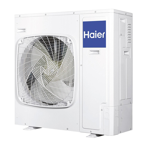
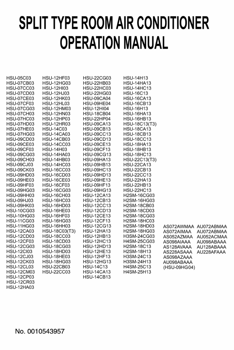
  9. Haier HBU-28CH03 User manual

Haier HBU-28CH03 User manual

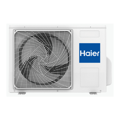
HBU-42CI03
HBU-42HI03
ROOM AIR CONDITIONER
OUTDOOR UNIT
No.0150500832
Before using the ir conditioner,ple se re d this m nu l c refully.
Ple se keep this m nu l properly for future use.
CONTENTS
Name of Parts----------------------1
Safety Cautions------------------2-3
Installation Pro edure---------4-13
INSTALLATION INSTRUCTIONS
HBU-42CH03
HBU-28HH03
HBU-28CH03
Air inlet
Air outlet
(Inside of unit)
Compressor
HBU-42CI03
HBU-42HI03
Air inlet
Air outlet
N me of P rts
1
(Inside of unit)
Compressor
HBU-28HH03
HBU-28CH03
HBU-42CH03
Air inlet
Air outlet
Below are listed three kinds of Safety Cautions and Suggestions.
WARNING!
CAUTION! In orre t operations may result in injuries or ma hine damages; in some ases may
ause serious onsequen es.
In orre t operations may result in severe onsequen es of death or serious injuries.
INSTRUCTIONS: These information an ensure the orre t operation of the ma hine.
Be sure to onform with the following important Safety Cautions.
The S fety C utions should be t h nd so th t they c n be checked t ny time when needed.
If the onditioner is transferred to the new user, this manual should be as well transferred to the
new user.
S fety C utions
C refully re d the following inform tion in order to oper te the irconditioner
correctly.
WARNING!
If ny bnorm l phenomen is found
(e. g.smell of firing), ple se cut off the
power supply immedi tely, nd cont ct
the de ler to find out the h ndling
method.
Don't dism ntle the outlet of the
outdoor unit.
The exposure of fan is very dangerous
whi hmay harm human beings.
swit h
off
In su h ase, to ontinue using the
onditioner will damage the onditioner,
and may ause ele tri al sho k or fire
hazard.
In orre t maintenan e and repairment
may ause water leak, ele tri al sho k
and fire hazard.
When need m inten nce nd rep irment,
c ll de ler to h ndle it.
After long time use of ir-conditioner
the b se should be checked for ny
d m ges.
If the damaged base is not repaired, the
unit may fall down and ause a idents.
2
Air-conditioner c n't be inst lled in
the environment with infl mm ble
g ses bec use the infl mm ble g ses
ne r to ir-conditioner m y c use fire
h z rd.
Connect e rthing wire.
Use disch rge pipe correctly to ensure
efficient disch rge.
Earthing wire should not be on-
ne ted to the gas pipe, water pipe,
lightning rod or phone line, in-
orre t earthing may ause sho k.
In orre t pipe use may ause water
leaking.
Earthing
S fety C utions
WARNING!
Inst lled electric l-le king circuit
bre ker.
It easily ause ele tri al sho k without
ir uit breaker.
Ple se let the de ler be responsible for
inst lling the conditioner.
In orre t installation may ause water
leak, ele tri al sho k and fire hazard.
C ll the de ler to t ke me sures to
prevent the refriger nt from le king.
If onditioner is installed in a small
room be sure to take every measure in
order to prevent suffo ation a ident
even in ase of refrigerant leakage.
When conditioner is deinst lled or
reinst lledde ler should be respon-
sible for them.
In orre t installation may ause water
leaking, ele tri al sho k and fire hazard.
No goods or nobody is permitted to
pl ced on or st nd on outdoor unit.
The falling of goods and people may
ause a idents.
Don't oper te the ir-conditioner with
d mp h nds.
Otherwise will be sho ked.
Only use correctly-typed fuse.
May not use wire or any other materials
repla ing fuse, other-wise may ause
faults or fire a idents.
3
Note :
(1). Fix the parts with s rews
(2).Don't intake the strong wind dire tly to the
outlet air-flow hole.
(3).A one meter distan e should be kept from the
unit top
(4).Don't blo k the surroundings of the unit with
sundries
Inst ll tion Procedure
2. Selection of the pl ce of inst ll tion
1. Accessories
"Edging" for prote tion of ele tri wires from an
opening edge.
Sele t the pla e of installation satisfying the following onditions and, at the
same time, obtain a onsent from the lient or user.
Edging
Pla e where air ir ulates.
Pla e free from heat radiation from other heat sour es.
Pla e where drain water may be dis harged.
Pla e where noise and hot air may not disturb the neighborhood.
Pla e where there is not heavy snowfall in the winter time.
Pla e where obsta les do not exist near the air inlet and air outlet .
Pla e where the air outlet may not be exposed to a strong wind.
Pla e surrounded at four sides are not suitable for installation. A 1m or more
of overhead spa e is needed for the unit.
Mount guide-louvers to pla e where short- ir uit is a possibility.
When installing several units, se ure suffi ient su tion spa e to avoid short
ir uiting.
Wind dire tion
NO
(2) Inst ll tion where the re with strong winds.
Install the unit so that the air outlet se tion of the unit must NOT be fa ed
toward wind dire tion.
(1) Open sp ce requirement round the unit
L
2
L
3
L
1
500
(Servi ing
spa e)
Air outlet
Air inlet
Air
inlet
Case
Distan e
Unit: mm
open open
open
500
150
150 300
300 0
L1
L2
L3
III III
Inst ll tion of outdoor unit
4
(2) Inst ll tion sketch of outdoor unit
310
635
340
Power Wiring Terminal
Power Wiring
Distribution Hole
3. Inst ll tion of outdoor unit
Fix the unit in a proper way a ording to the ondition of a pla e where it is
installed by referring to the following .
(1) Inst ll tion
Inst ll tion of outdoor unit
5
Inst ll tion Procedure
HBU-28CH03
HBU-28HH03
(b) Foundation an hor
(a) Con rete foundation
Install the unit so that the angle of in lination must be less than 3 degrees.
Note: (1) Give enough room for the on rete
foundation to fix by an hor bolts. Note: (1) Pla e the on rete foundation deep enough.
Unit
To fix by bolts
An hor bolt Con rete foundation
Unit
Con rete foundation
An hor bolt
(a) Con rete foundation (b) Foundation an hor
Con rete foundation
Unit
An hor bolt
An hor bolt
Con rete foundation
Unit
To fix by bolts
2
5
862
730
410
Power Wiring Terminal
Power Wiring
Distribution Hole
646
447
25
Inst ll tion of outdoor unit
6
Inst ll tion Procedure
1008
830
HBU-42CH03
340
HBU-42CI03
HBU-42HI03
580
380
948
Inst ll tion of outdoor unit
7
Inst ll tion Procedure
Outdoor
unit
Gas pipe
Liquid
pipe
Flare onne tion
Indoor
unit
stop valve
stop valve
4. Refriger nt piping
25
1250
HBU-42CH03 HBU-42CI03 HBU-42HI03
HBU-28CH03 HBU-28HH03
(2) Piping size
Install the removed flare nuts to
the pipes to be onne ted, then
flare the pipes.
(3) Limit tions for one w y piping length nd vertic l height difference.
Pre autions for refrigerant piping
Do not twist or rush piping.
Be sure that no dust is mixed in piping.
Bend piping with as wide angle as possible.
Keep insulating both gas and liquid piping.
Che k flare- onne ted area for gas leakage.
Conne ting method (indoor unit)
Apply refrigerant oil at half union as large and flare nut.
To bend a pipe, give the roundness as possible not to rush
the pipe.
When onne ting pipe, hold the pipe entre to entre then
s rew nut on by hand, refer to Fig.
Be areful not to let foreign matters, su h as sands enter
the pipe.
(4) Piping connection
For ed fastening without entering
may damage the threads and ause a
gas leakage.
Pipe dia Fastening torque
Liquid pipe 6.35mm
Gas pipe 15.88mm
Liquid pipe 9.52mm
Gas pipe 19.05mm
14.2-17.2N.m
61.8-75.4N.m
32.7-39.9N.m
97.2-118.6N.m
Gas pipe 12.7mm 49.5-60.3N.m
Refriger nt piping
8
90+0.5
Inst ll tion Procedure
Model
One way piping length Verti al height differen e
(between indoor and outdoor)
less than 30 m
HBU-42CH03
HBU-42CI03
HBU-42HI03
HBU-28CH03 HBU-28HH03
less than 50 m
less than 15 m
less than 30 m
Gas pipe
Liquid pipe
Gas pipe
9.52x0.8mm
15.88x1.0mm
9.52x0.8mm
19.05x1.0mm
Liquid pipe
HBU-42CH03
HBU-42CI03
HBU-42HI03
HBU-28CH03
HBU-28HH03
In the first to third test steps, if the pressure drops, he k the leakage in ea h joint
use sense of hearing, feeling and soap water, et . methods to find the leaking point.
After onfirming the leaking point, welding it again or tighten the nut tightly again.
Che king the leaking point
First step: 0.3MPa (3.
0kg/ m
2
g) pressurize
over 3 minutes.
Se ond step: 1.5Mpa
(15kg/ m
2
g) pressurize
over 3 minutes. Large
leakage will be found.
Third step: 3.0 MPa
(30kg/ m
2
g) pressurize
about 24 hours. Little
leakage will be found.
After finishing onne tion of refrigerant pipe, it shall perform air tightness test.
The air tightness test adopts nitrogen tank to give pressure a ording to the pipe onne tion
mode as the following figure shown.
The gas and liquid valve are all in lose state. In order to prevent the nitrogen entering the
ir ulation system of outdoor unit, tighten the valve rod before giving pressure (both gas
and liquid valve rods).
Outdoor
Completely tightened
Flare part
Outdoor units
Manhole
Dis harging valve
3-way valve totally losed
(Gas side)
Low pressure peizometer
High pressure peizometer
Meter separator
Dropping valve
2-way or 3-way valve totally losed
(Liquid side)
Nitrogen tank
VL VH
Indoor units
Indoor
Flare part
9
From pressurizing to 24 hours later, ea h 1¡ differen e of ambient temperature
will make 0.01MPa(0.1kg/ m2g) pressure hange. It shall be orre ted during test.
Che k if the pressure drops
The pressure does not drop-passed
The pressure drops- he k the leaking point.
5. Air disch rging method
CYLINDER
OF
NITROGEN
SERVICE
HOUSE
LARGE
SLIP-ON
CONNECTOR
SWEAT
JOINT
TUBING
BRING
BRAZED
LINE
PRESSURE
GAUGE
CYLINDER
PRESSURE
GAUGE
Inst ll tion Procedure
Refriger nt piping
It shall use the va uum pump of (lower than -755mmHg)high va uum degree and large air
dis harging (over 40l/min).
The va uumizing time depends on the length of the onne ting pipe, generally is 1~2 hours.
When va uumizing, it shall be onfirmed both gas and liquid side valves are losed.
If after 2 hours va uumizing, it annot rea h the va uum degree below -755mmHg, it an be
va uumized for other 1 hour.
If after 3 hours va uumizing, it still annot rea h the va uum degree below -755mmHg, he k
if there is any leaking point and repair the them.
If after over 2 hours va uumizing, the va uum degree is below -755mmHg, lose the VL
and VH on the meter separator and stop va uumizing. 1 hour later to onfirm if the va uum
degree hanges. If hanges, it indi ates there is leaking point in the system. Che k the leaking
point and repair.
After finishing the above va uumizing, hange the va uum pump into refrigerant pump to
harge the refrigerant.
Use va uum pump to perform va uumizing. It is stri tly forbidden to use the
refrigerant to remove the air inside the system.
After air tightness test and dis harging all the nitrogen, onne t the va uum pump
as the following figure shown.
Refriger nt piping
10
When the total length (L) of the two units' onne ting pipe is less than 5m, it is
unne essary to harge additional refrigerant.
If the onne ting pipe (L) ex eeds 5m, it shall harge Mg additional refrigerant per meter.
That is: Refrigerant harging amount = (L-5) x M (g)
For HBU-28CH03,HBU-28HH03, HBU-42CH03, HBU-42CI03,HBU-42HI03 M=65
Only in COOLING operation an harge the additional refrigerant.
When harging, the refrigerant shall be harged from the harging nozzle of low pressure vavle.
Be arefull when harging refrigerant, do not let the air mix into the system,and must harge the
additional refrigerant in liquid ondition.
6. Piping and indoor unit va uumizing
7. Charging amount of refrigerant
2-wayor 3-way valve totally losed
(Liquid side)
Indoor units
Indoor Outdoor
Completely tightened
Outdoor units
Va uum pump
Dis harging valve
3-way valve totally losed
(Gas side)
Low pressure peizometer
High pressure peizometer
Meter separator
V LVH
Flare part
Flare part
P
Inst ll tion Procedure
HBU-28CH03
HBU-28HH03
5. Electric wiring
DANGER OF BODILY INJURY OR DEATH
TURN OFF ELECTRIC POWER AT CIRCUIT BREAKER OR POWER
SOURCE BEFORE MAKING ANY ELECTRIC CONNECTIONS.
GROUND CONNECTIONS MUST BE COMPLETED BEFORE MAKING
LINE VOLTAGE CONNECTIONS.
(1) Selection of size of power supply nd interconnecting wires.
Prec utions for Electric wiring
Ele tri wiring work should be ondu ted only by authorized personnel.
Do not onne t more than three wires to the terminal blo k. Always use round
type rimped terminal lugs with insulated grip on the ends of the wires.
Use opper ondu tor only.
Sele t wire sizes and ir uit prote tion from table below. (This table shows 20 m
length wires with less than 2% voltage drop.)
WARNING
30mA
Item
Model Phase
3
Swit h breaker
(A)
Cir uit breaker
Over urrent prote tor
rated apa ity (A)
Power sour e
wire size
(minimum)
30 20 2.5mm
2
140 36 4.0mm
2
Swit h
breaker
Earth leakage breaker
Leak
urrent
30 30mA
40
11
HBU-42HI03
Inst ll tion Procedure
Electric wiring
HBU-42CI03
HBU-42CH03
(2) Wiring connection
Make wiring to supply power to the outdoor unit, so that the power for the indoor
unit is supplied by
terminals.
For the det iled wiring connection with the indoor units, see the corresponding indoor
oper tion nd instruction m nu l.
Electric wiring
12
Inst ll tion Procedure
FIG.1
HBU-28HH03
W B
L N
Y/G
Y/G
POWER SUPPLY:
1PH,220-230V~,50Hz
To Indoor Unit
W B R BR GR
1 2 3 4 5
Y/G
Y/G
FIG.2
FIG.3
POWER SUPPLY:
3N~,380-400V,50Hz
N 1 2 3
Y/G
R S T
HBU-42CI03 HBU-42CH03 HBU-42HI03
To Indoor Unit
To Indoor Unit
W B R W B
1 2 3 L N
HBU-28CH03
Y/G Y/G
Y/G
POWER SUPPLY:
1PH,220-230V~,50Hz
Y/G
13
Electric wiring
Inst ll tion Procedure
(1) Before st rting test run (for He t pump models)
6. Test run
Confirm whether the power sour e breaker (main swit h) of the unit has been
turned on for over 12 hrs to energize the rank ase heater in advan e of operation.
(2) Test run
Run the unit ontinuously for about 30 minutes, and he k the following.
Su tion pressure at he k joint of servi e valve for gas pipe.
Dis harge pressure at he k joint on the ompressor dis harge pipe.
Temperature differen e between return air and supply air for indoor unit.
CAUTION
THIS UNIT WILL BE STARTED INSTANTLY WITHOUT "ON" OPERATION
WHEN ELECTRIC POWER IS SUPPLIED.BE SURE TO EXECUTE "OFF"
OPERATION BEFORE ELECTRIC POWER IS DISCONNECTED FOR
SERVICING.
This unit has a fun tion of automati restart system after re overing power stoppage.
WARNING
DO NOT CONNECT THE NEUTRAL WIRE TO , OR PHASE.
INTERCONNECTING WIRES MUST BE WIRED ACCORDING TO FIG.1
FIG.2 FIG.3.FIG.4.INCORRECT WIRING CAUSE EQUIPMENT DAMAGE.
N R S T
(3) Wiring procedure
1) Remove set s rews on the side before taking off the front panel toward
the dire tion shown in figure.
2) Conne t wires to the terminal blo k orre tly and fix the wires with a
wire lamp equipped nearby the terminal blo k.
3) Route the wires in a proper way and penetrate the wires through the
opening for ele tri wiring on the side panel.

Other manuals for HBU-28CH03

1

This manual suits for next models

4

Other Haier Air Conditioner manuals

Haier AS71S2SF1FA-BH User manual

Haier

Haier AS71S2SF1FA-BH User manual

Haier ESAM3059 User manual

Haier

Haier ESAM3059 User manual

Haier H2SM-18RA03 User manual

Haier

Haier H2SM-18RA03 User manual

Haier 2HUM18HA03 User manual

Haier

Haier 2HUM18HA03 User manual

Haier AU07NFPEUA User manual

Haier

Haier AU07NFPEUA User manual

Haier ESA3067 - annexe 1 User manual

Haier

Haier ESA3067 - annexe 1 User manual

Haier AB122ACEAA User manual

Haier

Haier AB122ACEAA User manual
Haier HPC12XCR User manual

Haier

Haier HPC12XCR User manual

Haier HTWR10VCK Assembly instructions

Haier

Haier HTWR10VCK Assembly instructions

Haier H2SM-18HC03/R2 User manual

Haier

Haier H2SM-18HC03/R2 User manual

Haier HWR08XC1 User manual

Haier

Haier HWR08XC1 User manual

Haier HSU-09RM03/R2 User manual

Haier

Haier HSU-09RM03/R2 User manual

Haier HWR12XC8 Instruction Manual

Haier

Haier HWR12XC8 Instruction Manual

Haier HPAC99ER User manual

Haier

Haier HPAC99ER User manual

Haier HWF05XCA User manual

Haier

Haier HWF05XCA User manual

Haier AS072AZADA User manual

Haier

Haier AS072AZADA User manual

Haier HPU-48C03/NAF User manual

Haier

Haier HPU-48C03/NAF User manual

Haier HWR05XC9 Instruction Manual

Haier

Haier HWR05XC9 Instruction Manual

Haier ESA424K User manual

Haier

Haier ESA424K User manual

Haier H3SM- - annexe 2 User manual

Haier

Haier H3SM- - annexe 2 User manual

Haier HSU-09RR03 User manual

Haier

Haier HSU-09RR03 User manual

Haier HSU-12CE03/R1 User manual

Haier

Haier HSU-12CE03/R1 User manual

Haier ESA3087 - 7,800-BTU Energy-Star Window Air... User manual

Haier

Haier ESA3087 - 7,800-BTU Energy-Star Window Air... User manual

Haier HPDlOXCM User manual

Haier

Haier HPDlOXCM User manual

Popular Air Conditioner manuals by other brands

Fujitsu ASYG 09 LLCA installation manual

Fujitsu

Fujitsu ASYG 09 LLCA installation manual

Mitsubishi Electric Mr.Slim MSZ-A24NA operating instructions

Mitsubishi Electric

Mitsubishi Electric Mr.Slim MSZ-A24NA operating instructions

Daikin FDA125A5VEB Installer and user reference guide

Daikin

Daikin FDA125A5VEB Installer and user reference guide

Daikin Split Sensira R32 Service manual

Daikin

Daikin Split Sensira R32 Service manual

GOETTL GH UNITS User's information manual

GOETTL

GOETTL GH UNITS User's information manual

Gree E-TAC Installation and operation instructions

Gree

Gree E-TAC Installation and operation instructions

Samsung AJ NBNDEH Series user manual

Samsung

Samsung AJ NBNDEH Series user manual

AHRI SUPERIOR Series Installation, operation & service manual

AHRI

AHRI SUPERIOR Series Installation, operation & service manual

Mitsubishi Electric PLA-SP BA Series Operation manual

Mitsubishi Electric

Mitsubishi Electric PLA-SP BA Series Operation manual

Kaden KSI R32 owner's manual

Kaden

Kaden KSI R32 owner's manual

Airwell YCV Series Service manual

Airwell

Airwell YCV Series Service manual

Matsui MAT-9KACW manual

Matsui

Matsui MAT-9KACW manual

GD Midea Refrigeration Equipment Elite Series Technical & service manual

GD Midea Refrigeration Equipment

GD Midea Refrigeration Equipment Elite Series Technical & service manual

Dettson COND-UHD-09 Installation instructions and homeowner's manual

Dettson

Dettson COND-UHD-09 Installation instructions and homeowner's manual

Friedrich 0 Installation and operation manual

Friedrich

Friedrich 0 Installation and operation manual

GE ASQ12AL Dimensions and installation information

GE

GE ASQ12AL Dimensions and installation information

Mitsubishi Electric MS-D30VC operating instructions

Mitsubishi Electric

Mitsubishi Electric MS-D30VC operating instructions

Frico AD100 Original instructions

Frico

Frico AD100 Original instructions

manuals.online logo
manuals.online logoBrands
  • About & Mission
  • Contact us
  • Privacy Policy
  • Terms and Conditions

Copyright 2025 Manuals.Online. All Rights Reserved.