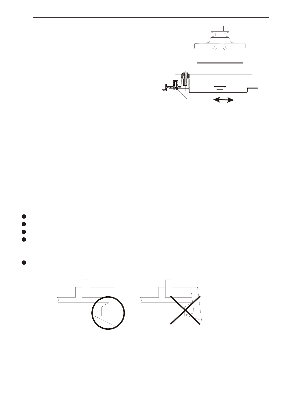
Haier XPB58-111S User manual


5
Do not stretch hands into the working
machine. It is dangerous even if the
rotation is slow. Take special care of
the children.
Handicapped or children without care
shall not use the machine.
Do not put any hot or heavy items
( such as the kettle with hot water )
on the washing machine.
Do not decompose, repair or alter the
machine by yourself.
Keep the machine away from direct
sunlight and heat source like the
heater.
Do not wash laundries with volatile
materials (such as thinner, petrol etc.).
Petrol
Thinner
WARNING AND CAUTIONS

Figure 1
NET DIMENSION
INSTALLATION AND ACCESSORY PARTS
6
Unit mm
The drainage shall be smooth with the drain hose.
4.If extra drain hose is needed , the inner
diameter of the extra hose shall not less
than 30mm, and the length shall not exceed
1.5m.
<10cm
> 30mm
<1.5m
1.The height of the drain hose shall be
less than 10cm , or the drainage will
not be smooth enough and cause
incomplete drainage.
2.Do not step on or press the drain hose.
3 If the drain hose is too long, cut it at mid
point. To make smooth drainage, cut the
front end of the hose slantingly.

How to change the direction of the drain hoses
7
INSTALLATION AND ACCESSORY PARTS
Extend the drain hose from the rear side
Figure 21 indicates the ex factory installation
position of the drain hose.
Put soft items on the ground. Lean the machine
down gently with the front surface facing the
ground. Take off the drain hose from the cabinet.
Take the hose out of the fixing groove.
(See to Figure 3).
Embed the drain hose into the groove along the side
of the spin tub in the order of (1)~(3), heading for the
side of the spin tub. (See to Figure 4).
Embed the drain hose into the groove with
hands. Take care not to damage the drain
hose in fastening the fixing clamp.
Figure 2
Figure3
Figure 4
Figure 5
Embed into the
groove in turn
Back
Extend the drain hose from the side of spin tub
Soft item
Soft item
Extend to the
spin tub side
Take out the drain hose from the fixing groove. Extend it from
the rear side as per the direction of the arrow. (When the drain
hose is extended from the rear side, it can be hung on the
point for drain hose at the two sides of the cabinet.)
(See to Figure 5).
Front

Spin tub shaft
Bearing seat
Figure 8
Oilite bearing
Inner lining of
the bearing seat
Fastening screw
Fastening screw of
the brake wheel
Inner lining of the
brake wheel
Brake wheel
Spin motor shaft
Points of Attention in After-sales Service
Be sure to switch off the power during dismantling or repair.
Be sure to use insulated wiring terminals and insulation box in connection of the wires, and
crimp and fix to proper position with suitable tools.
In welding connections with electric iron, be sure to twist the wires before welding, and insulate
with insulation tapes.
In welding the wires with electric iron, be sure not to touch the resin part and insulation part of
each switch.
The inlay connection wires and terminals shall not be loose or drop.
Do not make the wires touch the moving parts like the belt, pulley of the motor, brake bar etc.
Do not make the wires touch the sharp edges and high-temperature area.
In case that there are metal parts with the wires, do not make the wires touch the metal parts.
Insulation materials are needed between them.
After assembly, the washing machine shall act normally. Check if it leaks and if the sound and
vibration are normal.
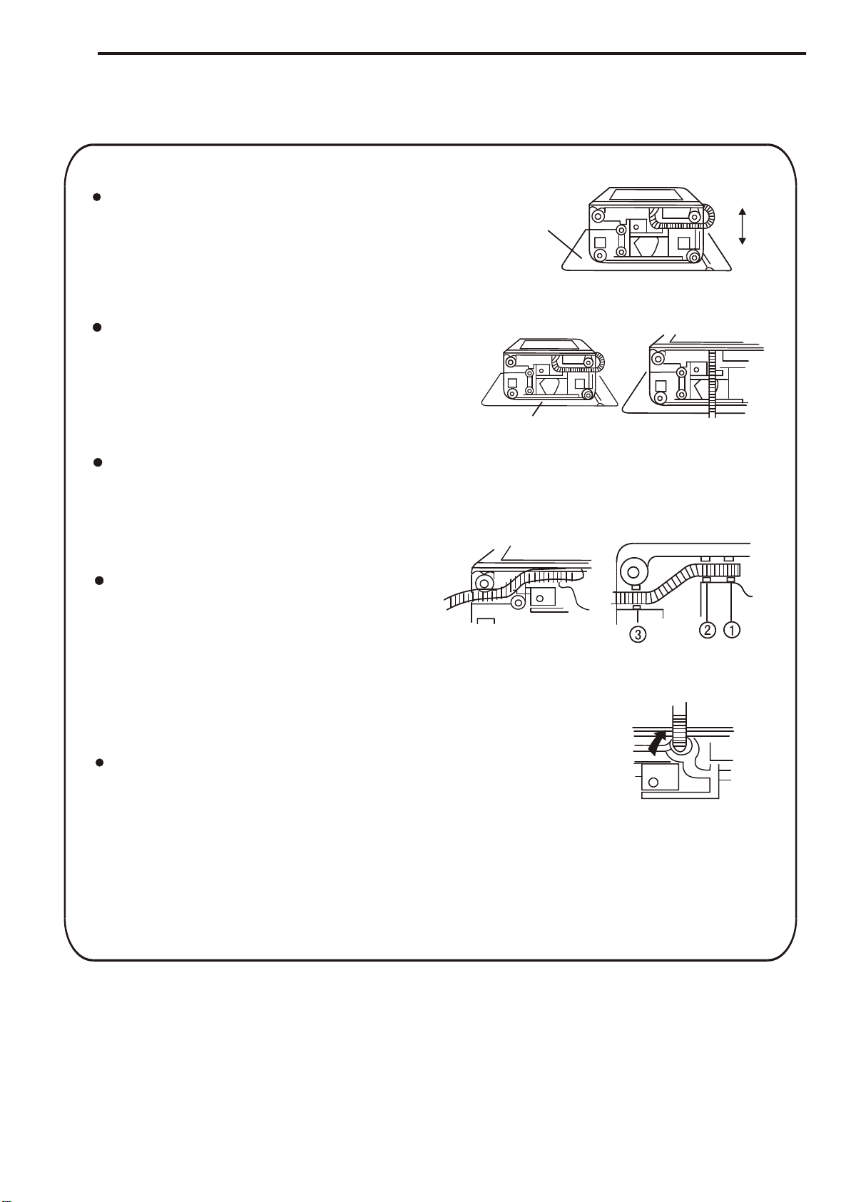
Dismantling and installation of the control panel component
Loosen the fastening screws. Pull towards the direction
indicated in the figure to dismantle the control panel. In
installation the beard shall lock into the installation hole
of the major frame. (Figure 6)
Dismantling and installation of the spin tub
frame component
Push the points marked with " " as indicated in
the figure and pull the spin tub frame towards
upper left direction to dismantle the spin tub frame
components. In installation, after set the rear side
of the spin tub frame to proper position, push the
four points marked with " " downwards by force
to resume its original position. (Figure 7)
Dismantling and installation of
the spin tub
Dismantle the spin tub frame component.
Loosen the fastening screw of the spin tub
shaft. The spin tub then can be taken out.
In installation, be sure to inlay the bulge of
the inner lining of the brake wheel into the
groove of the spin tub shaft. (Figure 8
Figure 6
Spin tub frame
Dismantle Installation
Figure 7
8
INSTALLATION AND ACCESSORY PARTS

Adjust the tension of the belt
Loosen the fastening screw at the back of the
base frame. Move the shift fixing gasket along
the direction indicated in the figure to adjust
the tension of the belt. After adjusting, fasten
the screw. (Figure9)
Dismantling and installation of the base frame
Dismantle the back cover. Loosen the wires. Loosen the
fastening screw of the spin tub shaft. Separate the shaft
from the brake wheel. Loosen the brake hook. Take off
the brake cable frame from the installation groove of the
twin-tub. Take off the V-belt. Take out the drain hose from
the groove of the base frame. Loosen the fastening screw
between the base frame and the cabinet to dismantle the
base frame component.
Dismantling and installation of the bearing seat
Once the bearing seat is taken off, it can not be utilized again. Therefore do not dismantle
it as far as possible. In case that it has to be replaced, please dismantle it as per following
sequence, then install a new bearing seat.
Dismantle the spin tub as per Clause 9.4. Then pull out the bearing seat.
Cut off the inner lining claw inside the bearing seat with cutting pliers and take it out.
Install the new bearing seat and inner lining.
The bearing seat is an inlay component. Be sure to aim the claw of the inner lining at the
hole of the tub then push it in. Please use suitable tools and add even pressure around
the tub.
After inlay the bearing seat, check if the claw is installed to proper position from the outside
of the twin-tub (Figure 10).
Figure 9
Figure 10
Right Wrong
Screw
9
INSTALLATION AND ACCESSORY PARTS

10
Figure 12
Figure 11
PARTS AND FUNTIONS
Control panel
Spin water-filling entrance
Spin timer
Wash selector
Wash timer
Transparent lid
Overflow filter
Wash water-filling entrance
Water level adjusting lever
Drain hose hook
Lint filter
Pulsator
Wash tub
Drain hose
Base frame
Outer cover of the spin tub
Inner cover of the spin tub
Spin tub frame
Spin tub
Cabinet
Power cord

8. Analysis Of The Common Breakdown
MAINTENANCE SERVICE AND TROUBLE SHOOTING
11
Insert the power plug , but the machine does not work
Wash part
YES
YES
YES
YES
YES
YES
YES
Switch on the power.
Replace the plug
or receptacle.
Replace with new power
supply cord.
Replace the fuse.
Inlay the connecting
wire again.
Check if the motor is good?
Replace the motor
Replace the wash timer
Replace the capacitor
Check if the capacitor
is good?
Poor contact or inferior
inside of the wash timer
Open the wash timer.
Check if the power source is available?
Check if the contact between
the plug and receptacle is good?
Check if the power supply
cord is good
Check if the fuse is good?
Check if the wash timer is opened ?
NO
NO
NO
No
NO
NO
NO
NO
NO NO
Check if the inlay of
the connecting wire
terminal is good?

MAINTENANCE SERVICE AND TROUBLE SHOOTING
Spin part
12
Check if the brake system
is detached?
Repair the brake system.
Check if the spin timer
is opened ?
NO
YES
NO
YES
NO
YES
NO
YES
NO
YES
NO
YES
NO
YES
NO
NO YES
YES
NO
Switch on the power.
Open the spin timer.
Check if the power source
is available?
Replace the plug
or receptacle.
Replace with new
power supply cord.
Check if the contact between
the plug and receptacle is good?
Check if the power supply
cord is good?
Replace the fuse.
Inlay the connecting
wire again.
Check if the fuse is good?
Check if the micro-switch is closed?
Check if the inlay of
the connecting wire
terminal is good?
Replace the capacitor.
Check if the capacitor
is good?
Replace the motor.
Repair the micro-switch,
make it closed.
Check if the motor is good

13
MAINTENANCE SERVICE AND TROUBLE SHOOTING
There is metal rubbing noise in braking
The washing noise is too large
If the brake arm
has brake block ?
NO Add the brake or replace
the brake arm.
Is the motor noise large?
Is the motor fastened tightly?
Is the belt too loose
or too tight?
Replace the wash timer
Is the wiring of
the wash timer proper?
Is the radiating pulley loose?
Is the pulsator rubbing the
bottom of the twin-tub?
8.4 The pulsator only rotates towards one direction
YES
NO
YES
YES
YES
NO
YES
NO
NO
Replace the motor.
Fasten the motor tightly.
Adjust the tension of the belt.
Fasten the radiating pulley.
Adjust the gap between the
pulsator and the twin-tub.
Adjust the wiring to
proper position.
YES
NO

Actual Circuit Diagram
There is overload protector installed in the motor. In case that the motor is overload or meets
breakdown in working, the protector will act and stop the motor. When the breakdown is
removed, the motor will resume normal working.
Figure13
WIRING DIAGRAM
14
Figure 12
red
Yellow
5A
fuse
Spin timer
Wash timer
Spin
motor
wash
motor
microswitch
purple
purple
gray
Brown
brown
blue
blue
blue
blue
orange
M
M
spin timer
microswitch
wash timer
wash
motor
capacitor
fuse
red
red
red
yellow
yellow
gray
gray
brown
brown
brown
blue yellow/green
orange
orange
purple
purple purple
blue
yellow
blue
Cabinet
Control
Panel
spin
motor

15
EXPLODED VIEW
34 5
7
8
9
10
11
12
15
35
6
14
13
36
21
22
38
31
33
34
39
27
25
19
20
26
29 30
40
41
12
43
47
48
49
50
51
52
53
54
55
64
62
44
45
56
58
60
59
61
57
63
42
46
66
24
92

16
EXPLODED VIEW
81
78
79
77
80
82
95
75
74
76
86
73
90
91
16
88
83
37
32
23
96
65
72
69
68
67
85
84
17
18
93
Manual
Carton box
94
28
87
89
70
71

LIST OF PARTS
17
Notes: the components marked with * in the remarks columns are damageable parts.
No. Part code Part name Model QTY. Remarks
100330009023 Water inlet component all-purpose 1
200330101569 Water inlet jointer component all-purpose 1
0030201887 XPB58-111S(Yemen)
0030201905 XPB75-111S(Indonesia)
0030201905 WMS650(Malaysia)
400330603049 Kick spring all-purpose 1
500330029007 Brake pullback band
component all-purpose 1
0030201888 XPB58-111S(Yemen)
0030201906 XPB75-111S(Indonesia)
0030201906 WMS650(Malaysia)
0030802665 XPB58-111S(Yemen)
0030802664 XPB75-111S(Indonesia) Grey
0030802666 XPB75-111S(Indonesia) Blue
0030802665 WMS650(Malaysia)
80030600056 Fastening screw all-purpose 1
900330303505 Dentate gasket all-purpose 1
00330101965 XPB58-111S(Yemen)
0030200700 XPB75-111S(Indonesia) Grey
0030201912 XPB75-111S(Indonesia) Blue
00330101965 WMS650(Malaysia)
11 00330303500 Protecting cover all-purpose 1
0030201873 XPB58-111S(Yemen) *
0030201876 XPB75-111S(Indonesia) *Grey
0030201886 XPB75-111S(Indonesia) *Blue
0030201873 WMS650(Malaysia) *
13 00330901529 Notice label all-purpose 1
0030802668 XPB58-111S(Yemen)
0030802667 XPB75-111S(Indonesia) Grey
0030802669 XPB75-111S(Indonesia) Blue
0030802668 WMS650(Malaysia)
15 0030200072 corrugation pipe all-purpose 1
16 00330101355 Shift fixing gasket all-purpose 1
17 00330802069 Tapping screw all-purpose 1
18 00330802069 Tapping screw all-purpose 8
0030201890 XPB58-111S(Yemen)
0030201899 XPB75-111S(Indonesia) Grey
0030201908 XPB75-111S(Indonesia) Blue
0030201890 WMS650(Malaysia)
20 0030200071 Overflow pipe all-purpose 1
21 0030801003 Drain pullback band
component all-purpose 1
22 0030200073 Long overflow pipe all-purpose 1
0030801877 XPB58-111S(Yemen)
0030802670 XPB75-111S(Indonesia) Grey
0030802672 XPB75-111S(Indonesia) Blue
0030802671 WMS650(Malaysia)
24 00330101986 Valve body component all-purpose 1
1
7Spin tub frame component
Lint filter
Overflow filter component
Cabinet
23 Base component
1
12
19
1
1
3Wash tub cover 1
14
10 Pulsator 1
6Spin tub cover
1
1

LIST OF PARTS
18
Notes: the components marked with * in the remarks columns are damageable parts.
No. Part code Part name Model QTY. Remarks
25 00330203001 Valve block all-purpose 1
26 00330603050 Valve spring all-purpose 1
27 00330101106 Valve cover A all-purpose 1
28 00330502089 Earthing wire components all-purpose 1
29 00330605502 Drain hose clamp all-purpose 1
0030802674 XPB58-111S(Yemen) *
0030802673 XPB75-111S(Indonesia) *Grey
0030802675 XPB75-111S(Indonesia) *Blue
0030802674 WMS650(Malaysia) *
31 0030801621 Bearing seat component all-purpose 1*
32 00330014011 Damping spring component all-purpose 4
33 00330067500 Retarder component all-purpose 1
34 00330802062 Tapping screw all-purpose 4
35 00330113501 Gland all-purpose 1
36 0030802415 Spin tub component all-purpose 1
37 00330802017 Tapping screw all-purpose 4
38 00330812048 Fixing screw all-purpose 1
39 00330703002 Safeguard bag all-purpose 1
40 00330829001 Locking belt all-purpose 2
41 00330105504 Crimp bushing B all-purpose 6
42 0030201059 Transparent lid all-purpose 1
0030201891 XPB58-111S(Yemen)
0030201900 XPB75-111S(Indonesia) Grey
0030201909 XPB75-111S(Indonesia) Blue
0030201891 WMS650(Malaysia)
0030201892 XPB58-111S(Yemen)
0030201901 XPB75-111S(Indonesia) Grey
0030201910 XPB75-111S(Indonesia) Blue
0030201892 WMS650(Malaysia)
0030600002 XPB58-111S(Yemen)
0030600039 XPB75-111S(Indonesia)
0030600002 WMS650(Malaysia)
0030502965 XPB58-111S(Yemen)
0030503370 XPB75-111S(Indonesia) Grey
0030503374 XPB75-111S(Indonesia) Blue
0030503806 WMS650(Malaysia)
47 0030201061 Wash shelf all-purpose 1
48 00330312502 Locating plate spring all-purpose 1
49 00330501009 Wash timer all-purpose 1*
50 00330802005 Tapping screw all-purpose 2
51 00330101096 Expanding gasket all-purpose 1
52 00330101095 Connecting rod all-purpose 1
53 00330109018 Selector cam all-purpose 1
54 00330802025 Tapping screw all-purpose 1
55 00330603505 Small pullback spring all-purpose 1
56 00330501003 Spin timer all-purpose 1*
57 00330101385 gemel seat all-purpose 1
58 00330802005 Tapping screw all-purpose 2
59 00330802005 Tapping screw all-purpose 2
4
1Control panel
Tapping screw
Small knob
Big knob 2
1
43
45
46
44
30 Drain hose component 1

LIST OF PARTS
19
Notes: the components marked with * in the remarks columns are damageable parts.
No. Part code Part name Model QTY. Remarks
61 0030400168 Wire unit all-purpose 1
0030201893 XPB58-111S(Yemen)
0030201902 XPB75-111S(Indonesia) Grey
0030201911 XPB75-111S(Indonesia) Blue
0030201893 WMS650(Malaysia)
0030600002 XPB58-111S(Yemen)
0030600039 XPB75-111S(Indonesia) Grey
0030600039 XPB75-111S(Indonesia) Blue
0030600002 WMS650(Malaysia)
0030201894 XPB58-111S(Yemen)
0030201903 XPB75-111S(Indonesia) Grey
0030201913 XPB75-111S(Indonesia) Blue
0030201894 WMS650(Malaysia)
65 00330028004 Brake hinge component all-purpose 1
66 00330105503 Crimp bushing A all-purpose
0030201889 XPB58-111S(Yemen)
0030201898 XPB75-111S(Indonesia) Grey
0030201907 XPB75-111S(Indonesia) Blue
0030201889 WMS650(Malaysia)
68 00330802005 Tapping screw all-purpose 3
69 00330506500 Capacitor all-purpose 1*
70 00330804001 Earthing bolt all-purpose 2
71 00330806003 Dentation gasket all-purpose 2
0030400106 XPB58-111S(Yemen)
0030400098 XPB75-111S(Indonesia)
00330502539 WMS650(Malaysia)
73 0030802323 V-belt all-purpose 1*
74 00330812034 Bolt A all-purpose 1
75 00330818001 Nut all-purpose 1
76 00330401007 Radiating pulley all-purpose 1
0034000050 XPB58-111S(Yemen)
0034000050 XPB75-111S(Indonesia)
0034000161 WMS650(Malaysia)
78 00330802514 Tapping screw all-purpose 3
79 00330206507 Shock pad, upper all-purpose 2
80 00330206506 Shock pad, lower all-purpose 2
81 00330206505 Shock pad A, upper all-purpose 1
82 00330206504 Shock pad A, lower all-purpose 1
0034000051 XPB58-111S(Yemen)
0034000051 XPB75-111S(Indonesia)
0034000162 WMS650(Malaysia)
84 00330802017 Tapping screw all-purpose 0
85 00330502046 Inner earthing wire
components all-purpose 1
86 0030801587 Brake pan component A all-purpose 1
87 00330307005 Wave gasket all-purpose 1
88 00330603013 Pullback spring all-purpose 1
89 00330047001 Brake wheel component all-purpose 1
*
*
Wash motor 1
1Power cord
83 Spin motor 1
3
64 Water-filling gui de groove
Back cover 1
1
Major frame 1
Tapping screw63
67
77
62
72

LIST OF PARTS
20
Notes: the components marked with * in the remarks columns are damageable parts.
No. Part code Part name Model QTY. Remarks
91 00330820004 Spring gasket all-purpose 3
0030502967 XPB58-111S(Yemen)
0030503371 XPB75-111S(Indonesia)
0030503808 WMS650(Malaysia)
0030502966 XPB58-111S(Yemen)
0030503372 XPB75-111S(Indonesia)
0030503807 WMS650(Malaysia)
0030502968 XPB58-111S(Yemen)
0030503373 XPB75-111S(Indonesia)
0030503375 XPB75-111S(Indonesia)
0030503809 WMS650(Malaysia)
95 00330812034 Bolt A all-purpose 1
96 00330802028 Nut all-purpose 1
1
Namepalte 1
94 Packing box
93 manual 1
92

Sincere Forever
Haier Group
Tel: 86-532-8938356
Web site: http: //www.haier.com
Table of contents
Other Haier Washer manuals

Haier
Haier XQG50-600SW User manual

Haier
Haier HLT20E User manual

Haier
Haier HWM70-FD10829 User manual

Haier
Haier WD9900 User manual

Haier
Haier HW70-B12CIN User manual

Haier
Haier HWM140-826S5 User manual

Haier
Haier JW-W51A User manual

Haier
Haier HLTW600AXW User manual

Haier
Haier JW-W40D User manual

Haier
Haier HW-C1270TVE-F - SERVICE User manual

Haier
Haier XQB70-10 User manual

Haier
Haier HW80-1482-F User manual

Haier
Haier HWD1000 - 1.7 cu. Ft. Washer/Dryer Combo User manual

Haier
Haier HWM65-728 User manual

Haier
Haier WMQ-12.P User manual

Haier
Haier XQBM22-C User manual

Haier
Haier HWM70-A User manual

Haier
Haier HW55-1010 User manual

Haier
Haier HNS1250TVE Quick start guide

Haier
Haier HW85-B1486NZP User manual