Haklift AC50-A User manual

1
Operate manual & Parts manual
Hand Pallet Truck with AC Pump
AC50-A WH10L-35-A
WH20L-51-A WH25L-51-A
Note: Owner and operator MUST read and understand this
operating instructions before use this pallet truck.

2
ATTENTION:
1. The waste packages should be sorted and put into solid dustbins according to the
materials and be collected disposal by local special environment protection bureau.
To avoid pollution, it’s forbidden to throw away the wastes randomly.
2. To avoid leaking during the use of the products, the user should prepare some
absorbable materials (scraps of wooden or dry duster cloth) to absorb the leaking
oil in time. To avoid second pollution to the environment, the used absorbable
materials should be handed in to special departments in terms of local authorities.
Thank you for choosing our pallet truck. For your safety and correct
operation, please carefully read the manual before use.
NOTE: All of the information reported herein is based on data available at the time of printing.The
factory reserves the right to modify its own products at any time without notice or incurring in any
sanction. Please verify with the factory for possible updates.
1. GENERAL SPECIFICATIONS
Model No.
AC50-A
WH10L-35-A
WH20L-51-A
WH25L-51-A
Standard
Low profile
Min. Fork Height
mm
85
35
51
Max. Fork Height
mm
200
85
156
Load Capacity
kg
5000
1000
2000
2500
Fork Length
mm
1150/1220
1120
1150/1220
Width Overall Forks
mm
540/685
530/685
540/685
Individual Fork Width
mm
180
160
Single load wheel
mm
No available
Ø50*70
Double load wheel
mm
Steel (78*66mm)
Nylon(80*66mm)
Ø34*58
Ø50*93
Type of load wheel
Nylon or PU(Polyurethane)
Steering Wheel size
mm
Ø178*50
Ø160*50
Ø180*50
Type of steering wheel
Nylon or Iron
Nylon or PU(Polyurethane)
Materials and specification are subject to change without notice.
2. TO ATTACH HANDLE TO PUMP UNIT
If you have purchased a wooden box of pallet truck, some assembly is required. Certainly, you
need some tools, a hammer, a pliers, a spanner, etc; and some parts, one axle with hole, two
elastic pins (Note one is in the axle), these parts are putted in a plastic bag, which is putted into
the draw-bar.
NOTE: The number of draw-bar and pump should be the same.

3
. Draw-bar 2. Pin 3. Axle with hole 4. Elastic pin 5. Fork frame
(Fig. 1)
When attaching the handle, you had better squat just behind the pallet truck. Then you:
2.1. Insert the draw-bar onto the pump piston (A), then use a hammer to insert the axle with
hole(K) into the hydraulic pump and draw-bar from the right to left. (See fig. 2 ).
2.2. Let control handle to the ‘LOWER’position, then pass
the adjusting nut (G), adjusting bolt (F) and chain (E)
through the hole of axle(K) with your hand (See fig. 3)
2.3. Press the draw-bar (D) down, take away the pin(#2) (See Fig. 1).
2.4. Let the control handle on ‘RAISE’position, then raise the lever plate (J) with the pin (#2)
and insert the adjusting bolt(F) into the front slot of lever plate, note to keep the adjusting nut
(G) on the under side of the lever plate(J).
2.5 Use a hammer to tap another elastic pin into the axle with hole (K). The Draw-bar is now
assembled to the pump.
Fig.2
Fig.3

4
3. TO ADJUST RELEASE DEVICE
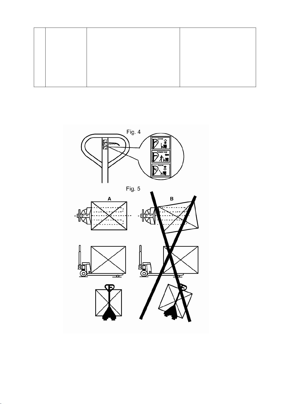
On the draw-bar of this pallet truck, you can find the control handle which can be regulated in three
positions :
Raise - handle down
Drive position - handle in center position
Lower - handle up, the lever moves back the drive position when released.
If however they have been changed, you can adjust according to following step:
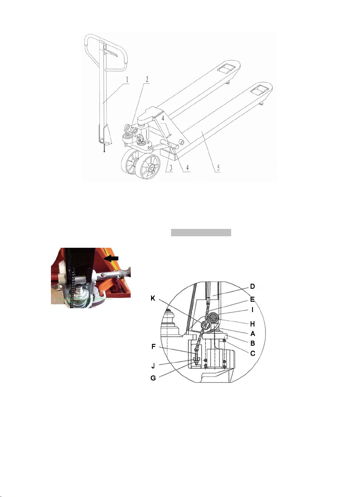
3.1 If the forks elevate while pumping in the DRIVE position, turn the adjusting nut on the adjusting
bolt or adjusting screw clockwise until pumping action does not raise the forks and the DRIVE
position functions properly.
3.2 If the forks descend while pumping in the DRIVE position, turn the nut or adjusting screw
counter-clockwise until the forks do not lower.
3.3 If the forks do not descent when the control handle is in the LOWER position, turn the nut or
adjusting screw clockwise until raising the control handle lowers the forks. Then check the DRIVE
position according to item 3.1 and 3.2 to be sure the nut or adjusting screw is inthe proper position.
3.4 If the forks do not elevate while pumping in the RAISE position, turn the nut or adjusting screw
counter-clockwise until the forks elevate while pumping in the RAISE position. Then check the
LOWER and DRIVE position according to item 3.1, 3.2 and 3.3.
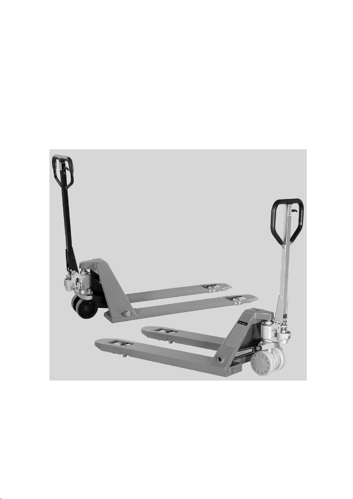
4. MAINTENANCE
Your pallet truck is largely maintenance-free.
4.1 Hydraulic Oil
Please check the oil level every six months. The oil capacity is about 0.3lt. Use the hydraulic type
oil according to temperature scale below.
Temperature
Oil
-20℃~+40℃
L-HV46 Hydraulic oil
4.2 HOW TO EXPELAIR FROM THE PUMP UNIT
The air may come into the hydraulic oil because of transportation or pump in upset position. It can
cause that the forksdo not elevate while pumping in the RAISE position. The air can been banished
in the following way: let the control handle on the LOWER position, then move the handle up and
down for several times.
4.3 DAILY CHECK AND MAINTENANCE
Daily check of the pallet truck can limit wear as much as possible. Special attention should be paid
to the wheels, the axles, as thread, rags, etc. It may block the wheels. The forks should be
unloaded and lowered in the lowest position when the job is over.

5
4.4 LUBRICATION
Use motor oil or grease to lubricate all moveable parts.
5. GUIDE TO SAFETY OPERATION
For safe operation of the Hand Pallet Truck, please read all warning signs and instructions
here and on the pallet truck prior to use.
5.1 Do not operate the pallet truck unless you are familiar with it and have been trained or
authorized to do so.
5.2 Do not operate the truck unless you have been trained and authorized. Givespecialattention to
the wheels, the handle assembly, the forks, and the lower control.
5.3 Do not use the truck on sloping ground.
5.4 Never place any part of your body in the lifting mechanism or under the forks or load. Do not
carry passengers.
5.5 We advise that operators should wear gloves and safety shoes.
5.6 Do not handle unstable or loosely stacked loads.
5.7 Do not overload the truck.
5.8 Always place loads centrally across the forks and not at the end of the forks (See Fig. 2).
5.9 The capacity of the truck assumes an evenly distributed load with the centre of the load being
at the halfway point of the length of the forks.
5.10 Make sure that length of the forks matches the length of the pallet.
5.11 Lower the forks to lowest height when the truck is not being used.
5.12 In other specific conditions the operators should take extra care in operating the truck.
6. TROUBLES SHOOTING
No
Trouble
CAUSE
ACTION
1
The forks can
not be up the
max. height.
- The hydraulic oil is not enough.
- Pour in the oil.
2
The forks can
not be lifted up.
- Without hydraulic oil.
- The oil has impurities.
- The nut is too high or the screw is too
close, keep the pumping valve open.
- Air come into the hydraulic oil.
- Fill in the oil.
- Change the oil.
- Adjust the nut or the
screw .(see item 3.4)
- Banish the air.(see item 4.2)
3
The forks can
not be
descended.
- The piston rod or pump body is
deformed resulting from partial loading
slanting to one side or over-loading.
- The fork was kept in the high position
for long time with piston rod bared to
arise in rusting and jamming of the rod.
- The adjusting nut or the screw is not
in the correct position.
- Replace the piston rod or
pump body.
- Keeping the fork in the lowest
position if not using, and pay
more attention to lubricate the
rod.
- Adjust the nut or the screw.
(see item 3.3)
4
Leaks
- Sealing parts worn or damaged.
- Some part cracked or worn into small.
- Replace with the new one.

6
5
The fork
descends
without the
release valve
worked.
- The impurities in the oil cause the
release valve to be unable to close
tight.
- Some parts of hydraulic system is
cracked or bored.
- Air come into the oil.
- Sealing parts worn or damaged.
- The adjusting nut or the screw is not in
the correct position.
- Replace with new oil.
- Inspect and replace the waste
parts.
- Banish the air. (See item 4.2)
- Replace with the new one.
- Adjusting the nut or the screw .
(See item 3.2)
*NOTE: DO NOT ATTEMPT TO REPAIR THE PALLET TRUCK UNLESS YOU ARE TRAINED
AND AUTHORIZED TO DO SO.

7
AC50-A General parts
Item
Parts No.
Parts details
Qty.
Item
Parts No.
Parts details
Qty.
1
17050101
Loading wheel
Steel Ø78*66
4
19
17050119
Shaft for loading wheel Ø20*94
4
17050101-1
NylonØ80*66
20
17050120
Bearing 6204#
8
2
17050102
Truck frame
1
21
17050121
Wheel cradle
2
3
17050103
Axle for joint Ø25*64
2
22
17050122
Spring pin Ø5*35
16
4
17050104
Joint for push rod M27
2
23
17050123
Spring pin Ø8*50
1
5
17050105
Connect axle Ø28*64
2
24
17050124
Bearing 6205#
2
6
17050106
Shaft for fork
frame Ø25
550
1
25
17050125
Steering wheel
Ø178*50mm
Steel
2
17050106-1
685
1
17050125-1
Nylon
2
7
17050107
Push rod
1150
2
26
17050126
Steering wheel cover
2
17050107-1
1220
2
27
17050127
AC Shaft for handle Ø20*103
1
8
17050108
Rocker arm
550
1
28
17050128
Shaft for steering wheel Ø28*194
1
17050108
685
1
29
17050129
Outside Circlip Ø60
1
9
17050109
Axle for wheel fork Ø22*176
2
30
17050130
Inside Circlip Ø25
2
10
17050110
Shaft for Push rod Ø18*115
2
31
17050131
Bearing #51112
1
11
17050111
Entry roller
2
32
17050132
Thrust Plate
1
12
17050112
Bolt (M10*55)
2
33
17050133
Grease nipple M8
1
13
17050113
Locking Nut M10
2
34
17050134
Grease nipple M6
1
14
17050114
Nut M27*1.5
2
35
17050135
Handle assy.
1
15
17050115
Snap ring Ø30
2
36
17050136
Steel ball Ø19
1
16
17050116
Snap ring Ø20
2
37
17050137
Dust cover
1
17
17050117
Axle Ø25*128
2
38
17050138
AC50 pump assy.
1
18
17050118
Wheel fork
2
39
17050139
Bolt M8*16
1

8
AC50-A Pump & handle parts details
Item
Parts No.
Parts name
Qty.
Item
Parts No.
Parts details
Qty.
1
17050201
AC pump body
1
1
17050301
Draw-bar
1
2
17050202
Composite gasket Ф10*2
1
2
17050302
Rubber pad
1
3
17050203
Plug screw M10*1*10
1
3
17050303
Spring Pin
1
4
17050204
Piston rod Ф45*290
1
4
17050304
Blade Spring
1
5
17050205
Seal washer UHSФ45*55*6
1
5
17050305
Torsional Spring
1
6
17050206
O-ring Ф45*3.55
1
6
17050306
Spring Pin
1
7
17050207
Dust ring DHSФ45*53*5/6.5
1
7
17050307
Control Handle
1
8
17050208
Small pump core Ф18*97
1
8
17050308
Roller
1
9
17050209
Spring cap 49*2*15
1
9
17050309
Spring Pin
2
10
17050210
Spring Ф5.5*48*115
1
10
17050310
Spring Pin
1
11
17050211
Dust ring Ф18*26*4.5/6
1
11
17050311
Release rod & chain assy.
1
12
17050212
Seal washer Ф18*26*5
1
12
17050312
Roller Axle
1
13
17050213
Pole Ф7*95
1
13
17050313
Pressure Roller
1
14
17050214
Lever plate 5#
1
14
17050314
Bushing
2
15
17050215
Nut M6*1
1
16
17050216
Screw M6*1*25
1
17
17050217
Spring pin Ф8*56
1
18
17050218
Integrated valve
1
*
17050219
Seal kits (Item 5/6/7/11/12)
1

9
WH20L-51-A/WH25L-51-A Frame parts details
Item
Parts No.
Parts details
Qty.
Item.
Parts No.
Parts details
Qty.
1
17070101
AC Oil pump
1
24
17070124
Shaft for double load wheel Ø17*94
4
2
17070102
Fork Frame for WH20L-51-A
1
25
17070125
Tandem Mounting Plate
4
17070102-1
Fork Frame for WH25L-51-A
1
26
17070126
Washer
4/8
3
17070103
Screw M6*14
1
27
17070127
Bearing
4/8
4
17070104
Rocker arm
540
1
28
17070128
Double loading
wheel Ø50*70mm
PU
4
17070104-1
685
1
17070128-1
Nylon
4
5
17070105
Bushing
2
29
17070129
Plastic gasket
2
6
17070106
Shaft Ø16*48
2
30
17070130
Grease nipple
1
7
17070107
Shaft for single load wheel Ø17*122
2
31
17070131
Steel ball Ø18
1
8
17070108
Locking Nut M6
2
32
17070132
Bolt M6*50
2
9
17070109
Outside Circlip 16
2
33
17070133
Entry roller
2
10
17070110
Joint for push rod
2
34
17070134
AC Handle assembly
1
11
17070111
Axle for joint Ø16*49
2
35
17070135
Shaft for steering wheel Ø25*170
1
12
17070112
Nut M20*1.5
2
36
17070136
Shaft for handle Ø20*103
1
13
17070113
Push rod
1220
2
37
17070137
Steering wheel cover
1
17070113-1
1150
2
38
17070138
Outside Circlip 20
2
14
17070114
Inside Circlip 25
2
39
17070139
Gasket
2
15
17070115
Shaft for fork frame
685
1
40
17070140
Bearing 6204
4
17070115-1
540
1
41
17070141
Steering wheel
PU Ø180*50
2
16
17070116
Single loading wheel
Ø50*93
PU
2
17070141-1
Nylon Ø180*50
2
17070116-1
Nylon
2
17070141-2
Rubber Ø180*50
2
17
17070117
Shaft for Push rod Ø14*82
2
42
17070142
Spring pin Ø8*45
1
18
17070118
Plastic gasket
4
43
17070143
Bearing sleeve
1
19
17070119
Exit roller
2
44
17070144
Thrust Plate
1
20
17070120
Spring pin Ø5*30
5/7
45
17070145
Oil cylinder circlip 55
1
21
17070121
Spring pin Ø5*35
4
46
17070146
Oil cylinder bearing 51111
1
22
17070122
Shaft for wheel fork Ø16*144
2
47
17070147
Bushing
4
23
17070123
Wheel fork
2

10
WH20L-51-A/WH25L-51-A Pump & handle parts details
Item
Parts No.
Parts name
Qty.
Item
Parts No.
Parts details
Qty.
1
17070201
AC pump body
1
1
17070301
Draw-bar
1
2
17070202
Small pump core Ø18*107
1
2
17070302
Rubber pad
1
3
17070203
Spring cover Ø49*2*15
1
3
17070303
Spring Pin
1
4
17070204
Big spring Ø5.5*48*115
1
4
17070304
Blade Spring
1
5
17070205
Dust ring Ø18*26*4.5/6
1
5
17070305
Torsional Spring
1
6
17070206
Seal washer Ø18*26*5
1
6
17070306
Spring Pin
1
7
17070207
Blocking bar Ø7*95
1
7
17070307
Control Handle
1
8
17070208
Dust ring Ø35*43*5/6.5
1
8
17070308
Roller
1
9
17070209
O-rings Ø35*3.55
1
9
17070309
Spring Pin
1
10
17070210
Seal washer Ø35*43*7
1
10
17070310
Spring Pin
1
11
17070211
Safety valve assy.
1
11
17070311
Release rod & chain assy.
1
12
17070212
Piston rod Ø35*278
1
12
17070312
Roller Axle
1
13
17070213
Plug M10*1*9.5
1
13
17070313
Pressure Roller
1
14
17070214
Washer 10*2
1
14
17070314
Bushing
2
15
17070215
Lever plate 8 #
1
16
17070216
Spring pin Ø8*52
1
17
17070217
Integrated valve
1
18
17070218
Nut M8
1
19
17070219
Screw M8*25
1
***
17070220
Seal kits AC(Item 5/6/8/9/10)
1

11
WH10L-35-A Frame parts details
Item
Parts No.
Parts details
Qty.
Item.
Parts No.
Parts details
Qty.
1
17060101
AC Oil pump (Special)
1
21
17060121
Shaft for handle Ø20*103
1
2
17060102
Fork Frame
1
22
17060122
Connected socket
4
3
17060103
Screw M8*16
1
23
17060123
Bolt M10*20
8
4
17060104
Rocker arm
530
1
24
17060124
Shaft for double load wheel Ø12*78
4
17060104-1
680
1
25
17060125
Spring pin Ø8*45
1
5
17060105
Bushing
2
26
17060126
Steel Double loading wheel Ø34*58
4
6
17060106
Shaft Ø16*48
2
27
17060127
Bearing 6204
4
7
17060107
Steel ball Ø18
1
28
17060128
Steering wheel Ø160*50
PU
2
8
17060108
Tandem Mounting Plate
4
17060128-1
Nylon
2
9
17060109
Spring pin Ø4*25
12
17060128-2
Rubber
2
10
17060110
Joint for push rod
2
29
17060129
Plastic gasket
2
11
17060111
Axle for joint Ø12*48
2
30
17060130
Grease nipple
1
12
17060112
Bushing Ø20*84
2
31
17060131
Oil cylinder circlip 55
1
13
17060113
Push rod (1120)
2
32
17060132
AC Handle assembly
1
14
17060114
Inside Circlip 25
2
33
17060133
Shaft for steering wheel Ø25*170
1
15
17060115
Shaft for fork frame
530
1
34
17060134
Thrust Plate
1
17060115-1
680
1
35
17060135
Steering wheel cover
1
16
17060116
Bolt Ø12*125
2
36
17060136
Outside Circlip 20
2
17
17060117
Nut Ø12
2
37
17060137
Gasket
2
18
17060118
Bearing sleeve
1
38
17060138
Spring pin Ø5*30
2
19
17060119
Oil cylinder bearing 51111
1
39
17060139
Bushing
4
20
17060120
Spring pin Ø5*35
2

12
WH10L-35-A Pump & handle parts details
Item
Parts No.
Parts name
Qty.
Item
Parts No.
Parts details
Qty.
1
17060201
AC pump body
1
1
17060301
Draw-bar
1
2
17060202
Small pump core Ø18*107
1
2
17060302
Rubber pad
1
3
17060203
Spring cover Ø49*2*15
1
3
17060303
Spring Pin
1
4
17060204
Big spring Ø5.5*48*115
1
4
17060304
Blade Spring
1
5
17060205
Dust ring Ø18*26*4.5/6
1
5
17060305
Torsional Spring
1
6
17060206
Seal washer Ø18*26*5
1
6
17060306
Spring Pin
1
7
17060207
Blocking bar Ø7*95
1
7
17060307
Control Handle
1
8
17060208
Dust ring Ø35*43*5/6.5
1
8
17060308
Roller
1
9
17060209
O-rings Ø35*3.55
1
9
17060309
Spring Pin
1
10
17060210
Seal washer Ø35*43*7
1
10
17060310
Spring Pin
1
11
17060211
Safety valve assy.
1
11
17060311
Release rod & chain assy.
1
12
17060212
Piston rod (Special)
1
12
17060312
Roller Axle
1
13
17060213
Plug M10*1*9.5
1
13
17060313
Pressure Roller
1
14
17060214
Washer 10*2
1
14
17060314
Bushing
2
15
17060215
Lever plate 8 #
1
16
17060216
Spring pin Ø8*52
1
17
17060217
Integrated valve
1
18
17060218
Nut M8
1
19
17060219
Screw M8*25
1
***
17060220
Seal kits AC(Item 5/6/8/9/10)
1
This manual suits for next models
3
Table of contents
Other Haklift Truck manuals