Halfords TH22502 User manual
INSTRUCTION MANUAL
2 TONNE LOW PROFILE
HYDRAULIC TROLLEY JACK
SWL (SAFE WORKING LOAD) UP TO 2 TONNE (2,000KG)
Item Code: 657099
Model: TH22502
INTRODUCTION
For your safety please read this manual before using any lifting equipment ensuring you fully
understand its operation and the safety procedures to be observed.
Ensure this manual is retained for future reference and that new users of this product read and
understand the content before they use the product.
GUARANTEE
This product is guaranteed by Halfords against manufacturing defects for a period of 12 months
from the date of purchase. This does not affect your statutory rights.
Should you experience a problem please return the product, together with the receipt and this
manual to your nearest Halfords store.
EC DECLARATION OF CONFORMITY
Date of issue: 1 September 2018
Reference batch number: ………………………………
(to be entered by the customer)
Directive:
Machinery Directive 2006/42/EC as amended by Directive 2009/127/EC
Conforming apparatus:
Product: Halfords 2 Tonne Low Prole Hydraulic Trolley Jack
Model: TH22502
Item code: 657099
Manufacturer:
Halfords Limited, Icknield street Drive, Redditch, Worcestershire, B98 0DE
Harmonised standards referenced or applied:
EN1494:2000 + A1:2008 Mobile or movable jacks and associated lifting equipment
The Supply of Machinery (Safety) Regulations 2008 Statutory instrument 2008
No.1597
The Supply of Machinery (Safety) (Amendment) Regulations 2011 Statutory
instrument 2011 No.2157
Halfords Limited hereby declare that the machine described below is both in its basic design
and construction and in the version marketed by us conforms to the relevant safety and health
related requirements of the appropriate EC Directives. This declaration shall cease to be valid
if modications are made to the machine without our approval.
Date of placement onto market: September 2018
Signed....................................................................
CHRIS HALL
Head of Quality
1 September 2018
CONTACT US
Halfords Ltd, B98 0DE.
www.halfords.com
Produced for Halfords
2
TONNE
lifting
capacity
LOW PROFILE
for improved
access
minimum
height
8.5cm
maximum
height
37.5cm
HAL1478/35812
WARNING
Failure to comply with these instructions can cause serious injury and damage to the
vehicle. If you are in any way unsure, do not attempt to use this product and consult
a qualied mechanic
1. Read and understand instruction manuals fully before use. Use only as specied.
2. Never overload this jack by exceeding its rated safe working load.
3. Check vehicle owner’s manual for gross vehicle weight.
4. This jack is for lifting purposes only.
5. Ensure all body parts are kept clear of the jack and vehicle during the raising and lowering
operation.
6. After lifting the vehicle, support immediately with properly rated axle stands.
7. Never work on or under a vehicle without using properly rated axle stands.
8. Only use on solid, even and level ground with the wheels chocked, the vehicle in gear
and its handbrake on.
9. Ensure that the wheels of the jack are rolling freely, all 4 wheels of the jack remain on the
ground during operation.
10. Always ensure that the load is centred on the jack saddle. Off centre loads can become
unstable and slip resulting in possible damage or injury.
11. Only use jacking points specied by your vehicle manufacturer. Some vehicles may require
a manufacturer specic adaptor. Check vehicle handbook for location and details.
12. Ensure vehicle jacking points are in good, sound condition with no corrosion etc.
13. Do not attempt to move or dolly the vehicle whilst on the jack.
14. This jack is not designed to support extensions, cradles etc.
15. Do not attempt to modify this jack in any way.
16. Do not attempt to use this jack if you suspect a fault.
17. Do not start the vehicle in its raised position.
18. Do not attempt to enter the vehicle and ensure all passengers are out of the car when using
this product.
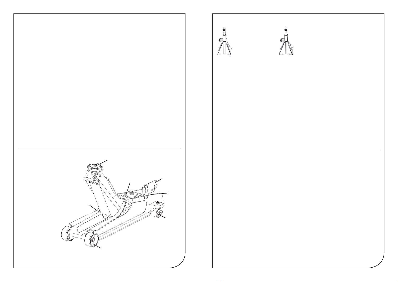
1. Front castor
2. Saddle
3. Handle fork
4. Release valve
5. Handle storage hook
6. Rear castor assembly
7. Jack carry handle
PARTS OF THE JACK
BEFORE FIRST USE
Air may become trapped in the hydraulic system during transit. To purge air:
1. Open the release valve by rotating the handle counter clockwise one full turn.
2. Place the handle in the handle socket and pump about 4 full strokes to purge the air from the
pump and valving.
3. Close the release valve. Pump the handle until the jack has reached full extension. Continue
to pump several times to purge air from under the ram.
4. Open the release valve and push ram into its lowest position. Close the release valve and
operate normally.
Note: If the jack responds immediately to pump action, it is free of air and ready for operation.
If not, repeat procedure.
INSPECTION BEFORE EACH USE
Visual inspection should be made before each use of the jack. Check for leaking hydraulic uid,
cracked welds and damaged, loose or missing parts.
Any jack which appears to be damaged in any way, found to be badly worn, operates abnormally,
or has been subjected to an abnormal load or shock MUST NOT BE USED.
Use Service Jack For
Lifting purposes
ONLY.
Always support
Vehicle with
Jack stands.
OPERATING INSTRUCTIONS
IMPORTANT: Only use jacking points specied by your vehicle manufacturer. Some vehicles may
require a manufacturer specic adaptor. Check vehicle handbook for location and details.
TO MOVE:
Place handle in operating lever. Do not move the jack when handle is on the release valve as this
may cause damage to the jack. Do not attempt to move the jack whilst under load.
TO LIFT THE VEHICLE:
1. Park the vehicle on solid, even and level ground. Apply the handbrake, place the vehicle
in gear (P if automatic) and chock the wheels that will remain on the ground.
2. Using the jack handle as a wrench, turn the release valve clockwise until fully tightened,
DO NOT OVERTIGHTEN.
3. Place the handle into the operating lever and position the jack under the jacking point of the
vehicle. Pump up and down until the saddle reaches the jacking point. Before lifting, ALWAYS
ensure that the load point is centred on the jack saddle and cannot slip. Off centre loads can
become unstable and slip resulting in damage or injury.
4. Once secure on the jacking point, begin to raise load to desired height by pumping the handle.
IMMEDIATELY support the vehicle by placing properly rated axle stands under a strong, stable
point on the vehicle. Consult the vehicle owner’s manual and axle stand instruction manual for
guidance. DO NOT CRAWL UNDER VEHICLE WHILE LIFTING VEHICLE OR PLACING OR
REMOVING JACK STANDS!
FOR YOUR SAFETY AND TO PREVENT INJURY:
1
2
3
7
4
6
5
5. Once the axle stands are properly located, VERY SLOWLY turn the release valve anti-
clockwise until the vehicle begins to lower onto the stands. Lower the vehicle slowly so as not
to shock load the jack stands.
6. BEFORE GOING UNDER THE VEHICLE ensure that all axle stands and chocks are correctly
in place and there is no chance of the vehicle becoming unstable.
TO LOWER THE VEHICLE:
Once repairs are completed raise the vehicle slightly, remove the axle stands and using the
handle as a wrench, VERY SLOWLY turn the release valve anti-clockwise until the vehicle begins
to lower.
CAUTION: Ensure all body parts are kept clear of the jack and vehicle during the raising and
lowering operation.
MAINTENANCE, CARE AND LUBRICATION
1. This jack contains no user serviceable parts. Any modication will render the jack unsafe.
2. All moving joints require lubricating often. Lubricate all linkages, pivot points and castor wheels
using a grease gun.
3. Regularly check the plunger, main piston and linkages for signs of corrosion. Clean any light
surface corrosion with a suitable maintenance spray. If the corrosion is deeper than surface
do not attempt to use.
4. When not in use keep the jack stored on all 4 wheels with the arm and plunger all the way
down to prevent corrosion.
TO ADD OIL
IMPORTANT When adding or replacing oil, ONLY use a quality hydraulic oil adhering to ISO VG 32
or similar. DO NOT use brake uid, transmission uid, alcohol, glycerine, detergent motor oil,
or dirty oil etc. as improper uid will cause serious internal damage to jack making it unsafe to use.
1. Place the jack on level ground with the lifting arm and plunger fully lowered.
2. Remove the top cover plate and clean the surrounding area of the oil ller plug and remove
ensuring that no dirt etc falls into the unit (see Fig.1).
3. Oil should be lled to level indicated in the diagram. If low, add hydraulic oil as required.
Maintenance and inspection: The owner and/ or user must maintain and inspect the jack in
accordance with the manufacturer’s instructions.
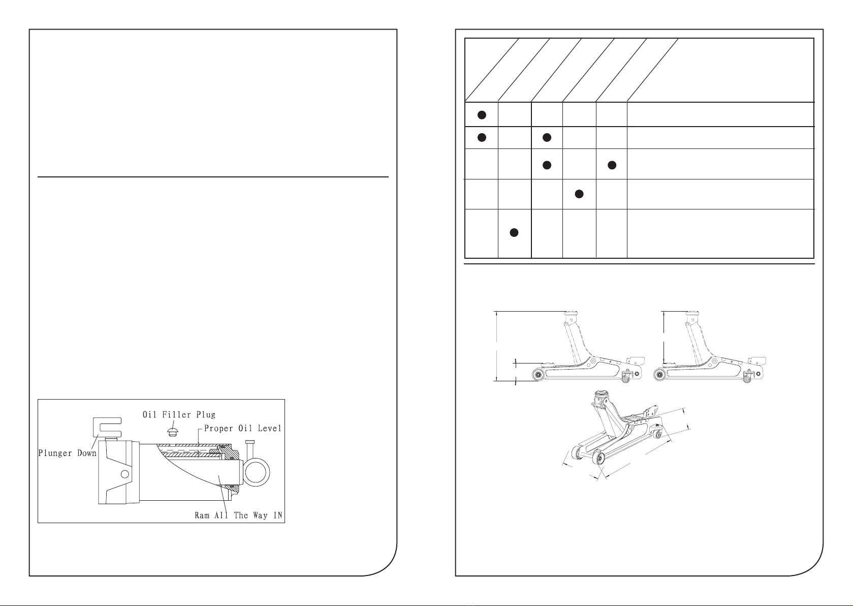
SPECIFICATIONS
max.375mm
min.85mm
290mm
560mm
145mm
212mm
Low height................................................................................8.5cm
High height.............................................................................37.5cm
Saddle diameter..........................................................................6cm
Handle length............................................................................50cm
Base length...............................................................................56cm
Chassis width.........................................................................21.2cm
All dimensions are approximate.
J
ack w
i
ll
not hold lo
ad
o
r
h
andle ri
s
e
s
Jack will not lift load
P
ROBLEMS
Jack will not lift to its
full height
Jack will not lower
completely
Jack will not lift smoothly
or jack feels spongy
Trouble Shooting Check List
The release valve is not closed.
Turn the valve clockwise tightly.
Low on oil.
Refill the jack to the correct level of oil.
The hydraulic system is filled with air.Open the
release valve,pump handle rapidly (4) full strokes to
purge air, close release valve.
Return spring is broken or linkages binding.
Repace spring if broken.Grease pivot shaft,oil all
lift arm linkages.
Discharge ball is not sealing hydraulic system and oil
may be dirty.Manually flush hydraulic system by
raising and lowering lift arm by hand.Open the release
valve,as required to raise and lower the lift
arm.Manually raise and lower lift arm.
max.375mm
min.85mm
290mm
560mm
145mm
212mm
Fig.1
This manual suits for next models
1
Other Halfords Jack manuals


Popular Jack manuals by other brands

Omega Lift Equipment
Omega Lift Equipment 18122C Operating instructions & parts manual

Pittsburgh
Pittsburgh 58816 Owner's manual & safety instructions

Unimec
Unimec TP Assembly instructions

Sonic
Sonic 4800703 instructions

BGS technic
BGS technic 70039 instruction manual

TradeQuip
TradeQuip 1128T owner's manual

VEVOR
VEVOR TJD-12000SP-F quick start guide

ULTIMATE SPEED
ULTIMATE SPEED URW 2 A1 HYDRAULIC TROLLEY JACK operating instructions

Stels
Stels 51131 user manual

Bushranger
Bushranger RJX01 instruction manual

Clarke
Clarke CTJ2500QLG Operating & maintenance instructions

Valex
Valex 1650520 Translation of the original instructions


