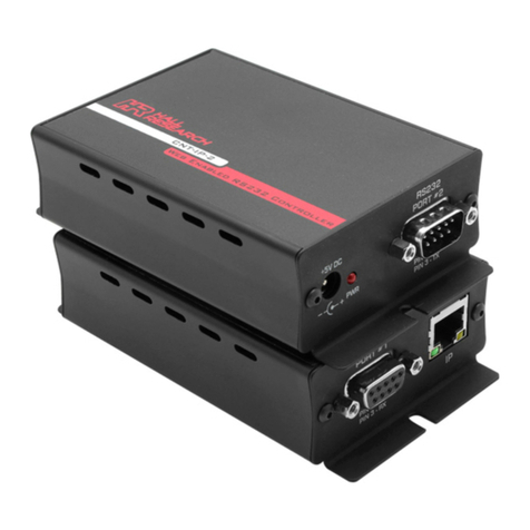
Hall Research Technologies HR-4P User manual

HR-4P
Programmable Controller
Order toll-free in the U.S. 800-959-6439
FREE technical support, Call 714-641-6607 or fax 714-641-6698
Mail order: Hall Research, 1163 Warner Ave. Tustin, CA 92780
Web site: www.hallresearch.com E-mail: info@hallresearch.com
CUSTOMER
SUPPORT
INFORMATION
UMA1164 Rev. NC


Programmable Serial Controller
1
TRADEMARKS USED IN THIS MANUAL
Hall Research and the Hall Research logo ( ) are trademarks of Hall
Research.
Any other trademarks mentioned in this manual are acknowledged to be
the property of the trademark owners.
FEDERAL COMMUNICATIONS COMMISSION
RADIO FREQUENCY INTERFERENCE STATEMENT
This equipment generates, uses, and can radiate radio frequency energy
and if not installed and used properly, that is, in strict accordance with
the manufacturer’s instructions, may cause interference to radio
communication. It has been designed to comply with the limits for a
Class A computing device in accordance with the specifications in
Subpart B of Part 15 of FCC rules, which are intended to provide
reasonable protection against such interference when the equipment is
operated in a commercial environment. Operation of this equipment in a
residential area is likely to cause interference, in which case the user at
there own expense will be required to take whatever measures may be
necessary to correct the interference.
Changes or modifications not expressly approved by the party
responsible for compliance could void the user’s authority to operate the
equipment.
This digital apparatus does not exceed the Class A limits for radio noise
emission from digital apparatus set out in the Radio Interference
Regulation of the Canadian Department of Communications.

Model HR-4P
2
Contents
1. Introduction .......................................................3
1.1 General................................................................................................3
1.2 Features ..............................................................................................3
1.3 Block Diagram .....................................................................................4
2. Package Contents .............................................4
3. Getting Started ..................................................5
3.1 GUI Installation Overview ....................................................................6
3.2 Installation Prerequisites......................................................................6
3.3 Software GUI Installation .....................................................................6
3.4 Using the Software ..............................................................................7
3.5 Button Selection...................................................................................7
3.6 Connect/Disconnect.............................................................................7
3.21 Tools................................................................................................16
4. Final Installation ..............................................18
4.1 Connections.......................................................................................18
5. Troubleshooting ..............................................19
5.1 Contacting Hall Research ..................................................................20
5.2 Shipping and Packaging ....................................................................20
6. Specifications ..................................................20
6.1 General..............................................................................................20

Programmable Serial Controller
3
1. Introduction
1.1 General
The Model HR-4P is a programmable RS-232 device designed for control & automation
of a Projector, LCD, or any other device with serial port and a compatible digital interface.
The unit has 4 configurable I/O lines that can sense dry contact closures or Voltage
levels. It can detect “Low to “High” or “High to Low” transitions as well as “High” or “Low”
on Power-Up. The RTS (Output) and CTS (Input) lines in the RS232 DB9 connector can
also be used to control an output or sense an input.
Each Input line state (high or low) can be configured to send RS232 commands at any
baud rate; control Digital Outputs or to optionally send IR Remote Control Codes.
Hall Research provides a powerful Windows® based application (available on-line at
http://www.hallresearch.com or on CD upon request) that is used to easily create
complex control sequences that describe the desired actions and to then upload them
into the HR-4P, via a user supplied Null Modem RS232 cable. The information is stored
in non-volatile E2Prom which retains the information even if the power is lost. As your
future needs change, the information can then be extracted from the HR-4P and modified
as needed or copied into other HR-4P units.
The HR-4P has the ability to store up to 10 different command strings and can learn up
to 32 different IR remote control codes for later playback.
1.2 Features
9Compact, Reliable, and Economical
910 user-programmable Command Strings
932 user-programmable IR Memory
9User configuration for up to 4 Inputs, 4 Outputs or any combination
9Optional IR Remote Control Learn and Playback
9Front panel LED Power indicator
9Windows™ GUI Software
9Made in USA

Model HR-4P
4
1.3 Block Diagram
Figure 1 – Block Diagram
Figure 2 – Top Rear Figure 3 – Top Front
2. Package Contents
One each of the following items:
•(1) 5 vDC , 2.6 ADC universal power supply (110 – 220 vAC 50/60 hZ) with
power cord
•(1) Users Manual
•(1) HR-4P Controller
NOTE
•The user needs to supply the appropriate RS232 cable (normally NULL
MODEM) to connect the HR-4P to a PC in order to program the HR-4P.
•The user needs to supply the appropriate RS232 cable (could be straight
or NULL MODEM) to connect the HR-4P to the Serial Device it will be
controlling.

Programmable Serial Controller
5
3. Getting Started
The HR-4P is a configurable Input/Output Controller device that for most installations is
configured to detect either a dry contact closure or a DC voltage and then send a pre-
programmed serial string to some device, typically a projector.
The unit comes from the factory setup with all 4 I/O lines configured for dry contact
closures and no pre-programmed actions.
You should be prepared with the necessary information and equipment to test
your installation prior to being put into service.
•If the HR-4P will be used to control a serial device, the required control codes
for that device should be obtained. For example, the code to turn on and off the
Projector.
•If the HR-4P will be used to interface to other electrical equipment such as
contacts, compatible power sources or outputs, the supporting electrical
information will be required. For example, an electrical schematic or drawing
that shows how the HR-4P to the other electrical equipment such as switches
or relays.
•A Windows™ compatible PC is required to program the HR-4P unit. Once
programmed, the PC is no longer required except when testing and
troubleshooting installations.
•Test the programmed units to ensure functionality before the final installation.
Select the desired interface for each of the I/O lines that will be used to control the HR-4P
unit. These are set on the I/O Tab of the GUI and then uploaded into the HR-4P unit.
•Switches or Relay Contact Interface – Select the ‘INPUT - CONTACT’ type
•External DC Power Sources – Select the ‘INPUT – VOLTAGE’ type (9-28 vDC)
•Relay Coils – Select the ‘OUTPUT’ type (each output can provide 40 mADC of
current)
See examples of connection wiring at the end of this manual.
The HR-4P unit must be programmed before being put into service to control
something. The programming is accomplished using GUI software installed on the
users PC. Follow the instructions below for installing the software GUI.

Model HR-4P
6
3.1 GUI Installation Overview
The HR-4P Programmer is a Windows Software GUI used to:
•Configure the input and output lines
•Upload and download configuration strings
•Learn or Enter Infra-Red Remote Control codes
•Create, Edit and Save unit configuration information
3.2 Installation Prerequisites
A compatible PC with Windows XP™ or later operating system is required.
•Microsoft™ .NET Framework 2.0 or later is required prior to installing the GUI.
•Most new PCs come with Microsoft™ .NET Framework 2.0 or later already
installed.
•If .NET Framework 2.0 or later is not installed on your PC, it can be found on
the Microsoft™ website.
3.3 Software GUI Installation
•If the software has been previously installed, you must UNINSTALL the
program from the Add/Remove Programs selection of the control panel.
•The software is installed by running the SETUP.EXE
program on the installation source.
•The typical user should be able accept all the default
settings.
Once the HR-4P Programmer Software installation has completed, a desktop icon
will appear as well as on the start menu under:
Start->Programs->Hall Research->HR-4P Programmer

Programmable Serial Controller
7
3.4 Using the Software
•Double click the desktop icon or its program menu selection and the
main screen will be displayed as shown below in Figure 4.
Note: Certain items are disabled if the GUI is NOT in communication with the HR-4P unit.
Figure 4 – Main Screen
3.5 Button Selection
•The main screen has four buttons on the left side (titled UPLOAD,
DOWNLOAD, SHOW CONFIG and CONNECT) and two buttons near the
bottom right corner of the Main screen as shown in Figure 1, which allows
users to quickly access the most commonly used functions.
3.6 Connect/Disconnect
•In order for the software to communicate with the HR-4P unit, it must be
connected to serial port on the computer.
oClick the Communications tab to verify or change the COM port selection.
This setting will be remembered for future use.
oTo open a serial connection to the unit, click the Connect button on the left
side of the screen to attempt a connection to the HR-4P. The button will
automatically change and say Disconnect. There are also Connect and
Disconnect buttons on the Communications tab that perform the same
functions.
If a connection was established between the software and the unit, the
GUI main screen will activate any previously disabled features. Note that
the bottom lower left of the screen will always show the current
connection status. This status bar will change color when the status
changes to draw the user’s attention.
oTo close the serial connection, click the Disconnect button on the left side of
the screen, or click the Disconnect button in the Communications tab.

Model HR-4P
8
3.7 Show Config
•Click the Show Config button to display the current configuration present in
the GUI. Figure 5 below shows an example of a unit’s configuration. All INPUT
Strings and IR Codes are available
•Configuration settings can be saved and loaded from disk by using the “FILE”
menu at the top of the main screen.
•Configuration settings can be uploaded into the HR-4P unit by clicking the
Upload button displayed on the left of the main screen.
•Configuration settings can be downloaded in the GUI by clicking the Download
button displayed on the left of the main screen.
Figure 5 – Sample Configuration Display
3.8 Download
•Click the Download button on the left of the Main screen to
retrieve the current configuration strings stored in a HR-4P unit
and into the GUI software.
•As the configuration screens are downloaded, the GUI interface will update
with the retrieved settings.
•If the configuration string for a specific condition needs to be viewed or
modified, you can click the Download Single button to the right of the
configuration text box as shown.
Note
Downloading or uploading user configuration strings is ONLY allowed
when the HR-4P unit is in the program mode (The power led is
blinking).

Programmable Serial Controller
9
3.9 Upload
•Click the Upload button on the left of the Main screen to store the
current configuration strings in a HR-4P unit from the GUI
software. All information stored in the HR-4P will be overwritten.
•If the configuration string for a specific condition needs to be uploaded, you can
click the Upload Single button to the right of the configuration text box as
shown.
3.10 Main Screen Tabs
•The HR-4P Programmer consists of four different pages in a tabular format.
Each Tab has a specific function suited to a particular task.
Configuration
•The Configuration tab page as seen in Figure 6 is the default tab shown
at software startup.
oThis tab allows the user to build configuration strings.
oA configuration string can be created to perform one or more specific
actions based on a particular condition.
oA configuration string can be up to 250 bytes long, and it can be any
combination of serial, time delays, IR codes, outputs, and pulses
actions. Each type of command; Serial, Time Delay, IR, Output and
Pulse each use a few bytes for identifying the desired action. For
example, a Serial Commands uses XX+2 bytes where XX is the
number of bytes the user defines. So… “Hello” uses 4 bytes + 2
bytes for the serial command.
•Condition – consists of 5 different real-world discrete inputs
oCTS, Input 1, Input 2, Input 3, and Input 4.
oTheir state can be high or low.
•Action
•Serial is used to send specific serial characters to a device
•IR is used to send an IR code to an IR receiver
•Delay is used to add a time delay
•Output is used to toggle a specific output on and off
•Pulse is used to send timed on/off/on or off/on/off to a output

Model HR-4P
10
Figure 6 – Configuration Tab
3.11 Serial Commands
•A serial command can send data to any standard serial device with selectable
baud rate and parity. When sending serial commands, you can also specify a
delay between characters to meet varying requirements.
•Serial commands can be mixed with other actions for the same input. For
example, you may have a projector configuration string like “PWR_ON”
followed by a DELAY followed by an OUTPUT. There is no limit to the number
of actions that can be added as long as the 250 character limit is observed.
•Hexadecimal characters may be entered by using &H in front of the 2 digit
Hexadecimal character.
•Select the desired Condition and change Action to Serial. Commands are
entered in the Command text box. When done, the user clicks the Add button
to append the command to the existing user string as shown in Figure 7.
Figure 7 – Serial Commands

Programmable Serial Controller
11
3.12 IR Codes
•IR code’s can be part of the configuration string. Supported IR formats are
available for sending known IR Addresses and Commands. Ensure that the IR
Protocol, Address and Commands have been tested to ensure proper
response from the controlled devices. A compatible IR Emitter is required to
send IR Codes.
•Select the desired Condition and change Action to IR. When done, the user
clicks the Add button to append the command to the existing user string as
shown in Figure 8.
Figure 8 – IR Codes
•Up to 32 IR Codes that have been ‘learned’ can be transmitted from the unit. A
compatible IR detector is required to LEARN IR Codes. A compatible IR
Emitter is required to send IR Codes.
•Select the desired Condition, change Action to IR, change IR Protocol to
Memory Recall and select the desired location that the IR code was saved
into.
•When done, the user clicks the Add button to append the command to the
existing user string as shown in Figure 9.
Figure 9 – IR Memory Recall

Model HR-4P
12
3.13 Time Delay
•Time delay’s can be added to configuration strings as needed. Delay’s can
from milliseconds to 255 minutes. Multiple delays can be entered if longer
times are required. Each of the minutes, seconds and milliseconds fields is
limited to 0 to 255.
•When done, the user clicks the Add button to append the command to the
existing user string to the existing user string as shown in Figure 10.
Figure 10 – Time Delay
3.14 Output
•If any of the units I/O is configured as an output, you can control that output
based on a specific input condition.
•Select the Output from the Action drop-down menu and pick a desired output
channel state, either ON or OFF.
•When done, the user clicks the Add button to append the command to the
existing user string as shown in Figure 11.
Figure 11 – Output

Programmable Serial Controller
13
3.15 Pulse
•If any of the units I/O is configured as an output, you can pulse that output one
or more times based on a specific input condition. The Pulse Width and Delay
between Pulses is selectable in milliseconds. The delay is only required when
more than one pulse is being sent.
•Select the Pulse from the Action drop-down menu and pick a desired output
channel, the Number of Pulses and the Pulse Width.
•When done, the user clicks the Add button to append the command to the
existing user string as shown in Figure 12.
Figure 12 – Pulse
3.16 I/O Control
•The I/O Control tab as shown in figure 13 allows the user to configure any or
all four discrete I/O as inputs or outputs.
•An input can be as Input-Contact, which is for normal ‘dry-contact’ type
devices or Input-Voltage which can be a DC voltage from 9-28 vDC.
•Any I/O configured as inputs may have the current status
read by clicking the I/O Status button.
•Any I/O configured as outputs may have the output state set by selecting the
appropriate control button.
•RTS is an OUTPUT, CTS is an INPUT. Action based configuration strings can
be created for the CTS Input only.
•The HR-4P unit can be assigned a unique address value from 01 to 99. This is
used as part of the “Long Command Format” mode when serially
communicating with the unit. Only the HR-4P unit with that unique address will
respond to RS232 commands. All HR-4P unit addresses receiving the serial
information must be unique otherwise incorrect operation will occur!
•All HR-4P units will respond to address 00. If multiple devices are connected
together serially, all devices will respond resulting in garbled RS232
transmissions.
oLong serial command format: HRTxxADR? where xx = 00 to 99
oShort serial command format: ADR?
•After using the Connect button and establishing communication with a HR-4P
unit, this tab will show the units Firmware Version Number as well as its
programmed Address.

Model HR-4P
14
•The Upload button is used to store this information in the HR-4P unit.
Figure 13 – I/O Control
3.17 IR
•The IR tab is used to configure the IR capabilities of the HR-4P unit. A
compatible IR Detector and Emitter are required to fully utilize the IR features.
•When the IR is configured as an Input, the HR-4P unit can learn any supported
IR codes from the user’s remote control. These IR codes can be stored into 1
of 32 IR Memory locations in the unit.
•IR codes stored in memory can an 8 character name associated with it, making
it easier to be identified later.
oCheck the IR Enabled box
oTo LEARN IR Codes
Select the Input radio button and click Upload
Install IR Detector on HR-4P Unit
Click the LEARN button
Press IR Remote Control button while pointing at IR Detector
Store code learned into IR Memory Location with name if desired
oTo SEND IR Codes
Select the Output radio button and click Upload
Install IR Emitter
Recall IR memory location
Click the SEND button to play the remote code from the HR-4P unit

Programmable Serial Controller
15
Note
Storing and Recalling IR codes from memory locations are ONLY allowed
when the HR-4P unit is in the program mode. (The LED is BLINKING)
Figure 14 – IR Learn
Figure 15 – IR Send
3.18 Communications
•The Communications tab page can be used to select a COM port of your PC
to talk to the HR-4P unit. Once, the preferred COM port is selected, pressing
the Connect button either in this tab page or on the left of the Main screen to
make a serial connection.
•Since the HR-4P’s serial port communicates at a fix baud rate of 19200, no
parity, 1 stop bit, and 8 data bits, those drop-down selections will be disabled.
The COM port is the only selection that needs to be set as shown in Figure 16.
Figure 16 – Communications

Model HR-4P
16
3.19 Menu System
The HR-4P Programmer consists of three menus which allow you to easily perform more
specific tasks.
3.20 File
The File menu consists of the following menu items as shown in Figure 17.
•New – Erase all the user configuration strings and IR codes and
start with a blank configuration.
•Open – Open a previously saved configuration file.
•Save – Saves a configuration file with the user specified filename.
•Exit – Exit the HR-4P Programmer Software.
•Exit – Exit the HR-4P Programmer.
Figure 17 – File Menu
3.21 Tools
The Tools menu consists of the following menu items as shown in Figure 18.
Note that certain items are disabled (grayed out) if the GUI is NOT in communication with the HR-4P unit.
•Reset Unit – Reset your HR-4P unit after a new I/O
configuration or IR configuration.
•Factory Defaults – Clears all information stored in HR-
4P unit and resets it to the factory shipped configuration.
•Refresh – Refreshes the tab page.
•Short Command Format – Set unit to short command
format.
•Long Command Format – Set unit to long command
format.
Figure 18 – File Menu
3.22 Help
The Help menu consists of the following menu items as shown in Figure 19.
•Contents – Display the help file contents. A previously installed
PDF reader is required in order to view the document.
•About… – Display the Version and Support information for the
GUI software.
Figure 19 – Help Menu

Programmable Serial Controller
17
3.23 RS232 Command Summary
The HR-4P uses a simple command protocol that can be used by other software in order
to control and/or configure the unit.
•The unit uses a baud rate of 19200, 8 Data bits, 1 Stop bit and No Parity for all
communications and from the device when it is RUN MODE (Power Led is
NOT blinking)
•The HR-4P supports both a short and long command format style.
•Long command format have the sequence HRTxx before the actual
command.
oThe xx is a numeric value from 00 to 99 which sets the units
address
oAll HR-4P units will listen to address 00 (for example
HRT00VER?)
oOnly units with the correct address that matches the xx address
value will respond or execute the commands received.
•Short command format uses only the command portion listed in the table
•<cr><lf> in the table below denote the CARRIAGE RETURN (0x0D) and
LINEFEED (0x0A) Characters
•Each command is terminated by a single CARRIAGE RETURN <cr>
Command Function Response
VER?<cr> Read Firmware version Version x.y<cr><lf> where X.Y is the
firmware version
ADR?<cr> Read Address of Unit Device address = nn<cr><lf>
ADnn<cr> Set an address of the unit to nn
nn = 00 to 99
Set device address (01-99)nn<cr><lf>
CLnm<cr> Configure I/O line n to m
n = 1 to 4
m = 1 : 2 : 3 : ? = contact input :
voltage input : output : status
Nothing except Status Reads return:
CLX1 = I/O line X configured as contact
type input<cr><lf>
CLX2 = I/O line X configured as voltage
type input<cr><lf>
CLX3 = I/O line X configured as
output<cr><lf>
IOnm<cr> Set or Read State of I/O line n to m
n = 1 to 4 = output
m = 0 : 1 : ? = low : high : status
Input X = 1 or 0<cr><lf>
Output X = 1 or 0<cr><lf>
TOGn<cr> Toggle the state of I/O line n
n = 1 to 4
Input X = 1 or 0<cr><lf>
Output X = 1 or 0<cr><lf>
IRCn<cr> Set or inquire IR
n = 0 : 1 : ? = input : output : status
IRC0 = IR configured as Rxd<cr><lf>
IRC1 = IR configured as Txd<cr><lf>
IRSn,m<cr> Send IR code stored in 1 of 32 IR memory
locations
n = 6 (Learned IR)
m = 1 – 32 (Memory Location)
Nothing

Model HR-4P
18
Command Function Response
IRSn,m,k<cr> Send IR code with a specified IR protocol, IR
address, and IR command
n = 0 - 5 (NEC, JVC, Sharp, RCA,
RC5, and Sony-sirc)
m = 0 - 255 = IR address in
DECIMAL
k = 0 - 255 = IR command in
DECIMAL
Nothing
IRPn<cr> Set or Read Current IR protocol State
n = 0 - 5 (NEC, JVC, Sharp, RCA,
RC5, and Sony-sirc)
n = ? = status
IRP0 = Current IR protocol = NEC<cr><lf>
IRP1 = Current IR protocol = JVC<cr><lf>
IRP2 = … and so on
RTSn<cr> Set or Read State of RTS line
n = 0 : 1 : T: ? = low : high : toggle
: status
Nothing except Status Reads return:
RTS? = RTS0<cr><lf> or RTS1<cr><lf>
CTSn<cr> Read State of CTS line
n = ? = status
CTS? = CTS0<cr><lf> or CTS1<cr><lf>
FDFT<cr> Factory default Are you sure (Y,N)?
User must send CAPITOL “Y” before 8
Second Timeout
RST<cr> Unit Reset/Restart
CMDn<cr> Set serial command format
n = S : L : ? = short : long : status
<ACK> Character
CMD? Returns:
Short command format or
Long command format
MODE<cr> Return current mode status
00 = Run mode
01 = Program mode
00 or 01<cr><lf>
RE<cr> or
re<cr>
Reserved – Active only in PROGRAM MODE Factory use only
WE<cr> or
we<cr>
Reserved – Active only in PROGRAM MODE Factory use only
RDIO<cr> Reserved – Active only in PROGRAM MODE Factory use Only
RDIN<cr> Reserved – Active only in PROGRAM MODE Factory use Only
4. Final Installation
4.1 Connections
•Connect the following items to the programmed HR-4P unit:
•External wiring to Terminal Board
•RS232 cable to serial device to be controlled
•Ensure switch in RUN position.
•Power Supply
Table of contents
Other Hall Research Technologies Controllers manuals