HR4-BREAKOUT Installation and Operation Instructions
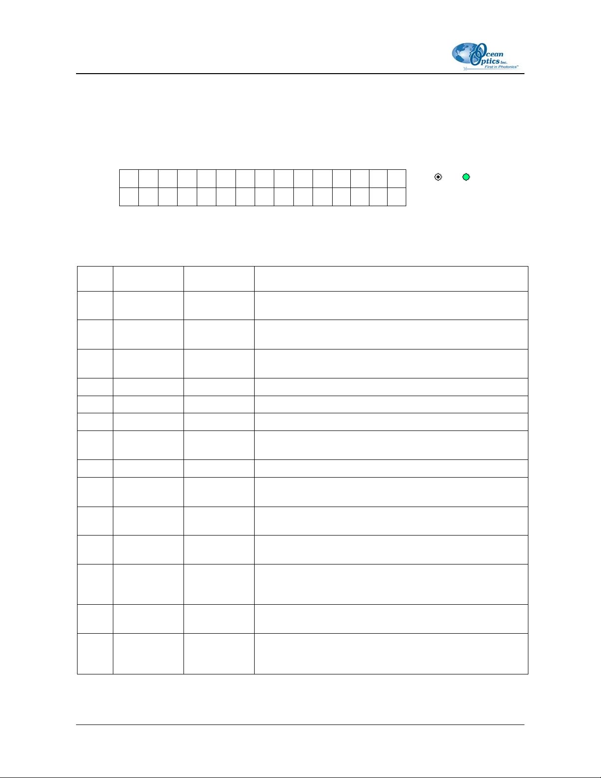
Pin # Function Input/Output Description
15 SPI Data In Input SPI Master In Slave Out (MISO) signal for communication to
other SPI peripherals
16 GPIO (4) Input /Output General purpose software-programmable, digital
input/output (channel number)
17 Single Strobe Output
TTL output pulse used as a strobe signal – Has a
programmable delay relative to the beginning of the
spectrometer integration period
18 GPIO (5) Input/Output General purpose software-programmable, digital
input/output (channel number)
19 SPI Clock Output SPI clock signal for communication to other SPI peripherals
20 Continuous
Strobe Output TTL output signal used to pulse a strobe – Divided down
from the master clock signal
21 SPI Chip
Select Output SPI Chip/Device Select signal for communication to other
SPI peripherals
22 GPIO (6) Input/Output General purpose software-programmable, digital
input/output (channel number)
23 Analog In
(0–5V) Input 13-bit low power, analog-to-digital input with a 0–5V range
24 Analog Out
(0–5V) Output 9-bit programmable output voltage with a 0–5V range
25 Lamp Enable Output TTL signal driven Active HIGH when the Lamp Enable
command is sent to the spectrometer
26 GPIO (7) Input/Output
General purpose software-programmable, digital
input/output (channel number)
27 Ground Input/Output Ground
28 GPIO (8) Input/Output
General purpose software-programmable, digital
input/output (channel number)
29 Ground Input/Output Ground
30 GPIO (9) Input/Output
General purpose software-programmable, digital
input/output (channel number)
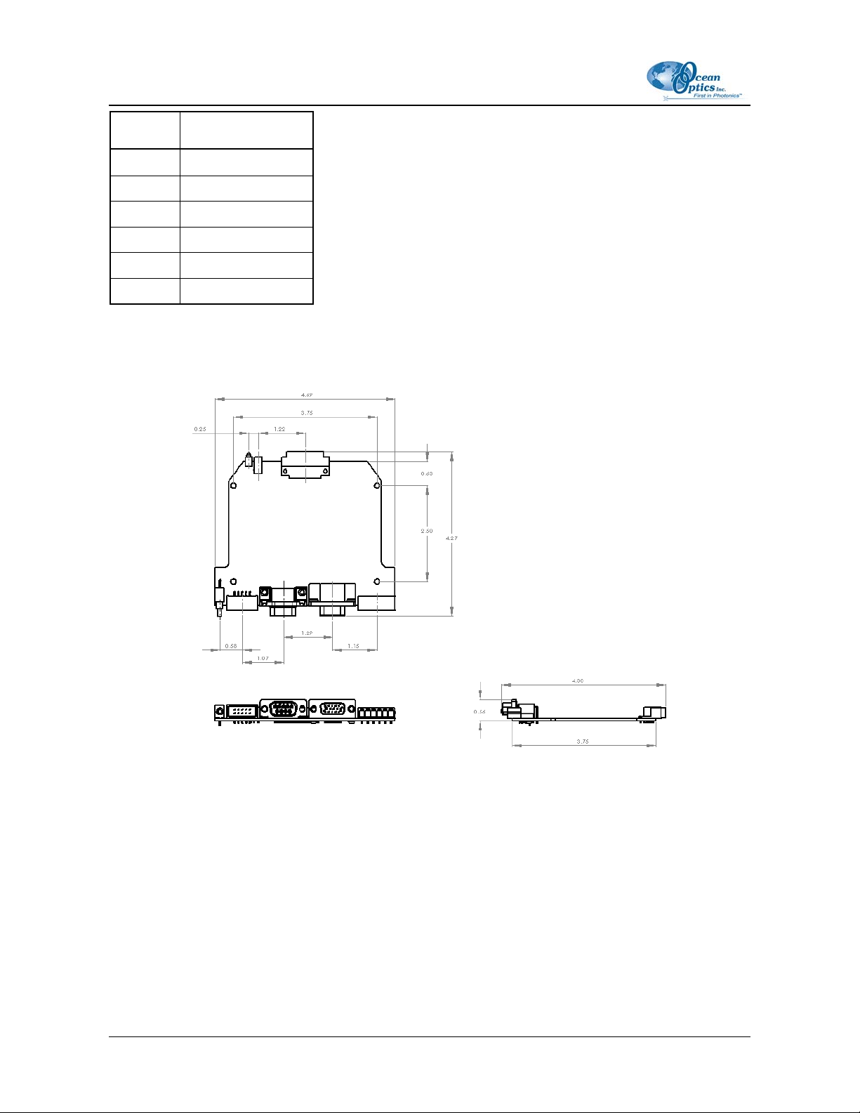
Circuit Board Connectors Pinout Information
The following tables list pinout information for the J2, J3, J4, J5, J6, and J7 connectors on the
breakout box circuit board.
212-00000-000-01-0805 5