manuals.online logo
Brands
  1. Home
  2. •
  3. Brands
  4. •
  5. Halsey Taylor
  6. •
  7. Water Dispenser
  8. •
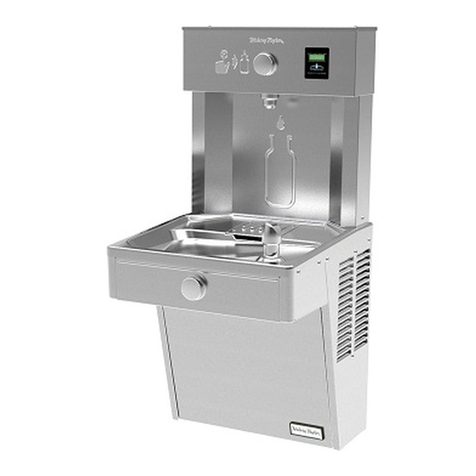
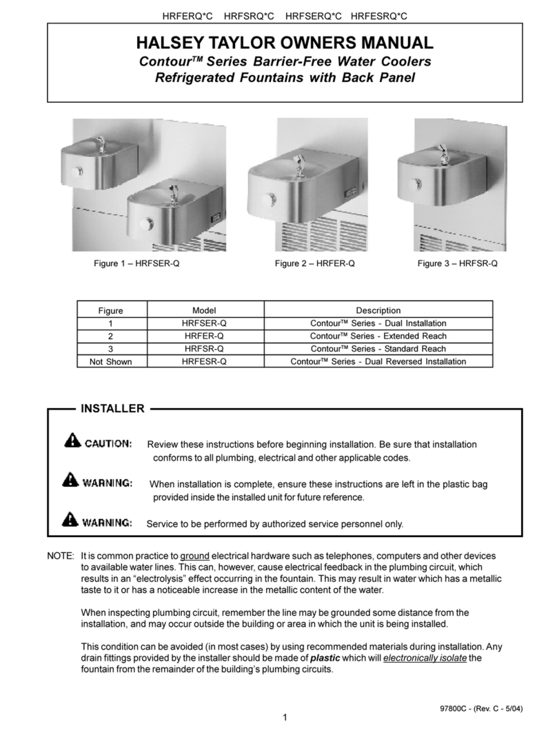
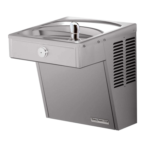
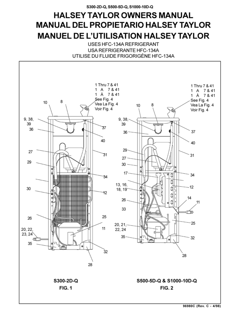
  9. Halsey Taylor HVRBLFR Series User manual

Halsey Taylor HVRBLFR Series User manual

Page 1 98952C (Rev. E - 01/18)
HVR8BLFR*1D HVR8BLFR*1D HVRDBLFR*C
Owners Manual
MANUAL DEL PROPIETARIO HALSEY TAYLOR
MANUEL DE L'UTILISATION HALSEY TAYLOR
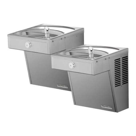
HVRBLFR™ Series Vandal-Resistant Water Coolers
Serie HVRBLFR™ enfriadores de agua a prueba de agresiones
Série HVRBLFR™ anti-vandalisme refroidisseurs d’eau
Page 2
98952C (Rev. E - 01/19)
HVR8BLFR*1D HVR8BLFR*1D HVRDBLFR*C
10 20
7
39
6
1
16
3
See Fig. 6
See Fig.6
25
25
27
38
21
11
19
4
32
37
27
27 5
21
9
33
27
37 8
32
33
21
27
6
16 16
2
1
22
12
41
See Fig. 6
40
42
43
15
43
21
See Fig. 6
Uses HFC-134A refrigerant
Note: Danger! Electric shock hazard. Disconnect power before servicing unit.
FIG. 1
Page 3 98952C (Rev. E - 01/18)
HVR8BLFR*1D HVR8BLFR*1D HVRDBLFR*C
LEGEND/LEYENDA/LÉGENDE
A = RECOMMENDED WATER SUPPLY LOCATION 3/8 O.D. UNPLATED COPPER TUBE CONNECT STUB WITH SHUT OFF (BY OTHERS) 3 IN. (76mm) MAXIMUM OUT FROM WALL
B = RECOMMENDED LOCATION FOR WASTE OUTLET 1-1/2” O.D. DRAIN STUB 2 IN. OUT FROM WALL
C = 1-1/2” TRAP NOT FURNISHED
D = ELECTRICAL SUPPLY (3) WIRE RECESSED BOX
E = INSURE PROPER VENTILATION BY MAINTAINING 6” (152 mm) (MIN.) CLEARANCE FROM CABINET LOUVERS TO WALL.
F = 7/16 BOLT HOLES FOR FASTENING UNIT TO WALL
FIG. 2
ORIFICE
HEIGHT
ALTURA DEL
ORIFICIO
HAUTEUR DE
L'ORIFICE
ORIFICE
HEIGHT
ALTURA DEL
ORIFICIO
HAUTEUR DE
L'ORIFICE
FINISHED FLOOR
PISO ACABADO
PLANCHER FINI
RIM
HEIGHT
ALTURA DE LA
CORONA
HAUTEUR DU
BORD
C
D
A
B
F25 1/8"
638mm
20 1/8"
511mm
18 3/4"
476mm
13 7/8"
352mm
C
L
C
L
4 1/2"
114mm
3 1/2"
89mm
6 1/4"
158mm
1 1/2"
38mm
10"
254mm
5"
127mm
2 7/16"
63mm
20 3/8"
518mm
37 1/2"
952mm
E
E
F
6 1/2"
166mm
5/16" (8mm) DIA. (10 HOLES)
8mm (10 AGUJEROUS)
8mm (10 TROUS)
18 1/16"
459mm
5 3/4"
146mm
1 3/8"
35mm
5 3/4"
146mm
1 3/8"
35mm
1 3/8"
35mm 1 3/8"
35mm
12 5/16"
312mm
4 1/8"
105mm
8"
203mm
18 5/8"
474mm
27"
686mm
ADA
REQUIREMENT
31 7/8"
810mm
32 15/16"
837mm
39 1/2"
1003mm
2 5/8"
67mm
HANGER BRACKET
FIJADOR DE SUSPENSION
SUPPORT DE SUSPENSION
5 3/4"
146mm 5 3/4"
146mm
6 3/4"
173mm
*REDUCE HEIGHT BY 3” FOR INSTALLATION OF CHILDREN’S ADA COOLER
Page 4
98952C (Rev. E - 01/19)
HVR8BLFR*1D HVR8BLFR*1D HVRDBLFR*C
IMPORTANT
ALL SERVICE TO BE PERFORMED BY AN AUTHORIZED SERVICE PERSON
HANGER BRACKETS & TRAP
INSTALLATION
1) Remove hanger bracket fastened to back of cooler by removing one (1) screw.
2) Mount the hanger bracket and trap as shown in Figure 2.
NOTE: Hanger Bracket MUST be supported securely. Add xture support carrier if wall will not provide adequate support.
IMPORTANT:
• 6 1/4 in. (159mm) dimension from wall to centerline of trap must be maintained for proper t.
• Anchor hanger securely to wall using all ve (5) 1/4 in. dia. mounting holes.
3) Install straight valve for 3/8” O.D. tube.
INSTALLATION OF COOLER
4) Hang the cooler on the hanger bracket. Be certain the hanger bracket is engaged properly in the slots on the cooler back as shown in Figure 2.
5) Loosen the two (2) screws holding the lower front panel at the bottom of cooler base and two (2) screws at the top (Use torx bits sold separately). Remove the front panel and
set aside.
6) Connect water inlet line--See Note 4 of General Instructions.
7) Remove the slip nut and gasket from the trap and install them on the cooler waste line making sure that the end of the waste line ts into the trap. Assemble the slip nut and
gasket to the trap and tighten securely. Also See General Instructions
8) Stream height is factory set at 45-50 PSI. If supply pressure varies greatly from this, adjust screw using the access hole in the pushbutton (insert screwdriver). CW adjustment
will raise stream and CCW adjustment will lower stream. For best adjustment, stream should hit basin approximately 6-1/2” (165mm) from bubbler.
22
21
Fig. 3
Thermostat Installation Detail
14
42
43
44
27
44
Fig. 4
Heater Strip Detail
WARNING!
This unit is frost resistant down to 0° F with no wind. Prevailing
winds can reduce the ability of the heater element to prevent
light freezing. If the ambient air temperature will drop below 0°
F, the cooler needs to be drained of all water by blowing out all
water lines, evaporator (item 20), and the drain trap. A heater
strip is used to heat the unit and will begin to cycle at 40° +/- 5°
F. A check at this temperature will ensure the heater is working
and the unit is resistant to light freezing.
ALSO, MAKE SURE THERE ARE NO PLASTIC OR
FLAMMABLE COMPONENTS DIRECTLY ABOVE THE
HEATER STRIP.
Wiring Diagram
(Freeze Resistant Model)
HEATER
THERMOSTAT
HEATER
SWITCH
HEATER
WHT
GND
BLK
FAN 1
0
1
1
1
2
1
3
MS
C
1
2
3
COLD CONTROL
(WATER)
RELAY
COMPRESSOR
1
4
Fig. 5
Page 5 98952C (Rev. E - 01/18)
HVR8BLFR*1D HVR8BLFR*1D HVRDBLFR*C
Fig. 6
(Refrigerated side shown)
30
28
23
1
27 (8)
25
40 (LH unit)
41 (RH unit)
1
1
45
45
45
33
14
17
17
17
35
36
17
17
13
27
17
27
29 (4)
34
26
27 (6)
31 24
27
32
(Items 31 & 24 also
used on the LH unit)
45
1
1
Basin
VANDAL RESISTANT
BUBBLER DETAIL
Page 6
98952C (Rev. E - 01/19)
HVR8BLFR*1D HVR8BLFR*1D HVRDBLFR*C
PRINTED IN U.S.A.
2222 CAMDEN COURT
OAK BROOK, IL 60523
630.574.3500
FOR PARTS CONTACT YOUR LOCAL DISTRIBUTOR OR VISIT OUR WEBSITE WWW.HALSEYTAYLOR.COM
97446C
98777C
98775C
36322C
0000000238
75524C
98776C
35839C
98773C
35900C
36012C
55996C
27124C
55931C
70432C
1000004447
56092C
1000001906
98530C
66703C
98724C
70002C
35909C
600985451640
28617C
28963C
22897C
0000001190
160270508640
70864C
110868642550
28596C
See Color Table
See Color Table
See Color Table
See Color Table
See Color Table
See Color Table
1000001602
1000001994
45929C
45929C
35906C
35907C
75506C
98684C
75520C
28551C
Bubbler Assy - VR
Kit - Compressor Mtg Hardware
Kit - Fan Motor/Blade/Shroud/Nut/Screws
Compressor Serv. Pak
Kit - Relay/Overload/Cover
Clip (Front & Rear Panels)
Kit - Condenser/Drier
Kit - Cold Control/Screws
Kit - Heat Exchanger/Drier
Power Cord (RH Unit)
Power Cord (LH Unit)
Strainer (See “General Instructions”)
Cover - Cold Control
Cover - Dispenser Bottom
Screw - 8-32 x .38 THTC
Kit - Drain Tube Assy.
Tubing - Poly (Cut To length)
Kit - Push Button/Sleeve/Spacer/Nuts/Screw
Kit - Regulator/Holder/Nut
Drier
Evaporator Replacement Assembly
Screw - #10 x 1/2” Lg. HHSM
FR Thermostat Assy.
Plug - Drain 1-1/2CP
Screen - VR
Basin - Stainless Steel
Panel - Bottom Dispenser
Kit - #10 Pinned Torx Screws/T-25 Bit
Strainer - Bright
Screw - #8 x .62 Torx/Slot
Screw - #10 - 24 x .75 Socket Head
Panel - Screen
Panel - RH Rear
Panel - LH Rear
Panel - RH Dispenser Side
Panel - LH Dispenser Side
Panel - Dispenser Front
Panel - Front Lower
Kit - Elbow 5/16” x 1/4” (3 Pack)
Kit - Tee 1/4” (3 Pack)
Wasteline (LH unit)
Wasteline (Refrig. Unit)
Heater Strip
Switch - Rocker
Screw - #10 x .75 HHSM
Kit - Drain Elbow/Gasket/Nut/Washer
Torx Tool - T25
Hanger Bracket
PART NO. DESCRIPTION
*REPLACE WITH SAME COMPRESSOR USED IN ORIGINAL ASSEMBLY.
NOTE: All correspondence pertaining to any of the above water
coolers or orders for repair parts MUST include Model No. and Serial
No. of cooler, name and part number of replacement part.
1
2
3
*4
5
6
7
8
9
10
11
12
13
14
15
16
17
18
19
20
21
22
23
24
25
26
27
28
29
30
31
32
33
34
35
36
37
38
39
40
41
42
43
44
45
Sold Separate
NS
ITEM NO.
115V PARTS LIST
Stainless Steel
PANEL COLOR
COLOR TABLE
Item No. 37
Part No.
Item No. 32
Part No.
Item No. 33
Part No.
Item No. 34
Part No.
Item No. 35
Part No.
Item No. 36
Part No.
28525C 28519C 28516C
28536C 28522C 22955C
Refrig. Unit
Stainless Steel
PANEL COLOR Item No. 37
Part No.
Item No. 32
Part No.
Item No. 33
Part No.
Item No. 34
Part No.
Item No. 35
Part No.
Item No. 36
Part No.
28539C 28519C 28516C
28528C 28522C 22955C
Left Unit COLOR TABLE
NS - NOT SHOWN

This manual suits for next models

2

Other Halsey Taylor Water Dispenser manuals
Halsey Taylor HydroBoost HTHBHVR8 Installation manual

Halsey Taylor

Halsey Taylor HydroBoost HTHBHVR8 Installation manual

Halsey Taylor HVRBL Series User manual
Halsey Taylor

Halsey Taylor HVRBL Series User manual

Halsey Taylor WM14A-BL-Q-1Q Series User manual

Halsey Taylor

Halsey Taylor WM14A-BL-Q-1Q Series User manual

Halsey Taylor HAC8FSCQ 1E Series User manual

Halsey Taylor

Halsey Taylor HAC8FSCQ 1E Series User manual

Halsey Taylor GBMAKV*C User manual

Halsey Taylor

Halsey Taylor GBMAKV*C User manual

Halsey Taylor HACFSCWSD1F User manual

Halsey Taylor

Halsey Taylor HACFSCWSD1F User manual

Halsey Taylor Contour Series User manual

Halsey Taylor

Halsey Taylor Contour Series User manual

Halsey Taylor HVR Series User manual

Halsey Taylor

Halsey Taylor HVR Series User manual

Halsey Taylor HVRBL Series User manual

Halsey Taylor

Halsey Taylor HVRBL Series User manual

Halsey Taylor HVRGRN8BL User manual

Halsey Taylor

Halsey Taylor HVRGRN8BL User manual

Halsey Taylor OVL User manual

Halsey Taylor

Halsey Taylor OVL User manual

Halsey Taylor HVR8HD 1A Series User manual
Halsey Taylor

Halsey Taylor HVR8HD 1A Series User manual

Halsey Taylor HOWC8F-Q Series User manual

Halsey Taylor

Halsey Taylor HOWC8F-Q Series User manual

Halsey Taylor HTVZDBL 1A User manual

Halsey Taylor

Halsey Taylor HTVZDBL 1A User manual
Halsey Taylor Contour Series User manual

Halsey Taylor

Halsey Taylor Contour Series User manual

Halsey Taylor RC8AQA User manual

Halsey Taylor

Halsey Taylor RC8AQA User manual

Halsey Taylor WCFS*G*L*R User manual

Halsey Taylor

Halsey Taylor WCFS*G*L*R User manual

Halsey Taylor HAC8EECBL 1F Series User manual

Halsey Taylor

Halsey Taylor HAC8EECBL 1F Series User manual

Halsey Taylor HTVEE Series User manual

Halsey Taylor

Halsey Taylor HTVEE Series User manual

Halsey Taylor RC8*C Series User manual

Halsey Taylor

Halsey Taylor RC8*C Series User manual

Halsey Taylor BFMRQ*A Series User manual
Halsey Taylor

Halsey Taylor BFMRQ*A Series User manual

Halsey Taylor WM14WQ 1L Series User manual

Halsey Taylor

Halsey Taylor WM14WQ 1L Series User manual

Halsey Taylor HTHB-HACG8SS-WF User manual

Halsey Taylor

Halsey Taylor HTHB-HACG8SS-WF User manual

Halsey Taylor GBMAKV*B User manual

Halsey Taylor

Halsey Taylor GBMAKV*B User manual

Popular Water Dispenser manuals by other brands

Global Industrial 761218 user manual

Global Industrial

Global Industrial 761218 user manual

Premier T2000 owner's manual

Premier

Premier T2000 owner's manual

Eurowater SILEX 1C instructions

Eurowater

Eurowater SILEX 1C instructions

Sears Water Softener installation manual

Sears

Sears Water Softener installation manual

Elkay LZO Series installation instructions

Elkay

Elkay LZO Series installation instructions

A.O. Smith TRIASOFT MINI user manual

A.O. Smith

A.O. Smith TRIASOFT MINI user manual

Kenmore 625.38454 owner's manual

Kenmore

Kenmore 625.38454 owner's manual

Mijar Smart B65 user manual

Mijar

Mijar Smart B65 user manual

GE FQSVF installation instructions

GE

GE FQSVF installation instructions

3M SGP Series installation manual

3M

3M SGP Series installation manual

NuvoH2O Studio System installation guide

NuvoH2O

NuvoH2O Studio System installation guide

ottimo 7323498 instruction manual

ottimo

ottimo 7323498 instruction manual

Water Control Corporation BrassMaster Plus TurfMaster Installation and operation manual

Water Control Corporation

Water Control Corporation BrassMaster Plus TurfMaster Installation and operation manual

Elkay LZ Series Installation, care & use manual

Elkay

Elkay LZ Series Installation, care & use manual

Excalibur Water Systems 1.5 " HIGH CAPACITY SIMPLEX WATER SOFTENER Installation and operation manual

Excalibur Water Systems

Excalibur Water Systems 1.5 " HIGH CAPACITY SIMPLEX WATER SOFTENER Installation and operation manual

Premier AF-40K installation instructions

Premier

Premier AF-40K installation instructions

Canature WaterGroup 785 Series owner's manual

Canature WaterGroup

Canature WaterGroup 785 Series owner's manual

Contigo AUTOSEAL Care and use instructions

Contigo

Contigo AUTOSEAL Care and use instructions

manuals.online logo
manuals.online logoBrands
  • About & Mission
  • Contact us
  • Privacy Policy
  • Terms and Conditions

Copyright 2025 Manuals.Online. All Rights Reserved.