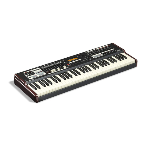
Hammond Sk PRO User manual

ORGAN
VOICE
SECTION

ORGAN Voice Section2
ORGAN VOICE SECTION
The tones produced by the ORGAN Voice Section are controlled by a set of nine Drawbars.
Drawbars, sometimes called Tonebars, are the heart and basis of the renowned Hammond Sound and
have been used since the first Hammond Organ Model A introduced in 1935. An explanation of how to
use these Drawbars is given later in this chapter of the Guide.
The ORGAN Voice Section can produce three different types of tones. Tone Wheel Organ replicates the
performance of a vintage Hammond Organ, Transistor Organ replicates the sounds of various combo
organs using solid-state technology, and Pipe Organ, which produces authentic pipe organ stops. This
will be explained later in this chapter of the Guide.
To hear the ORGAN Voice Section, Press the ORGAN button in the ALLOCATE button section. The LED
will light.

ORGAN Voice Section 3
uDRAWBAR SELECT buttons
These buttons allow you to use the Drawbars to control sounds for UPPER. LOWER and PEDAL Parts. If an
LED above a button is lit, the Drawbars will control the tones represented by that button.
tUsing the DRAWBAR SELECT buttons
The following examples are designed to acquaint you with the DRAWBAR SELECT buttons.
IMPORTANT NOTE: Before doing the following examples, make sure only the ORGAN ALLOCATE
button is “ON” (LED lit).
TRY THIS:
1. Press the UPPER button in the DRAWBAR SELECT button section to turn it “ON” (red LED lit).
2. Create a Drawbar registration - for example, 88 8800 008. You can confirm the registration by
consulting the Information Center Display.
3. Play some notes on the manual. You will hear the notes play with the Drawbar registration
you just set up.

ORGAN Voice Section4
Now, we will add a Drawbar registration to the LOWER Part.
TRY THIS:
1. If the 3PART ORGAN button is not “ON,” press it to turn it “ON.” An orange LED will light and
the SPLIT button will also turn “ON.” This is necessary in order to hear the LOWER
Registration.
2. Press the LOWER button in the DRAWBAR SELECT button section to turn it “ON” (LED lit).
3. Create a Drawbar registration - for example, 00 8400 000. You can confirm the registration by
consulting the Information Center Display.
4. Play some notes on the lower portion of the keyboard. You will hear the notes play with the
Drawbar registration you just set up.
Finally, here is how to add a Pedal or Bass registration.
TRY THIS:
1. Press the PEDAL button in the DRAWBAR SELECT button section to turn it “ON” (red LED lit).
2. Create a Pedal Drawbar registration - for example, 60 0000 000. You can confirm the
registration by consulting the Information Center Display.
NOTE: The Pedal tones are created by using ONLY the first brown Drawbar and the first white
Drawbar. This is explained in more detail on page 170.
3. Press the PEDAL TO LOWER button to transfer the Pedal tones to the manual and play some
notes on the left end of the manual. You will now hear the notes play with Pedal tones added.
uPlease Read
On the SK PRO, Drawbar Parameter changes for the PEDAL Part (“P”) will not be heard unless both the 3
PART ORGAN, Split and PEDAL TO LOWER buttons are “ON” or a MIDI Pedal clavier is connected.
Notice that only two (2) Drawbar settings are shown for the Pedals in the Information Center Display. On
most Hammond Organs with two manuals and pedals, there are two Drawbars for controlling the Pedal
tones - one at “16'" pitch and the other at “8'” pitch. The SK PRO recreates this by using the Sub-
Fundamental Drawbar (marked “16'”) and the Fundamental Drawbar (marked “8'”) to control the Pedal
sounds. For more information consult page 170.
ORGAN Voice Section 5
uPATCH EDIT - ORGAN
This FUNCTION Mode Menu allows you to make various changes to the characteristics of the ORGAN
Voice Section.
tAccessing the PATCH EDIT - ORGAN FUNCTION Mode using the MENU/EXIT button:
1. From any of the PLAY Mode screens, press the MENU/EXIT button to see the PATCH EDIT
screen. The COMBINATION box will be highlighted.
2. Press the DIRECTION “q” button to highlight ORGAN.
3. Press the ENTER button.

ORGAN Voice Section6
tAccessing the PATCH EDIT - ORGAN FUNCTION Mode using a Shortcut:
Press the UPPER and PEDAL DRAWBAR buttons together.
tAccessing the PATCH EDIT - ORGAN FUNCTION Mode via the APP MENU:
1. From any of the PLAY Mode screens, Press and Hold the MANUAL “ ” button. The
Information Center Display should now look like this:
The box “EDIT COMBINATION” should be highlighted.
NOTE: The APP MENU may not display all Voice Sections, depending on which Voice Sections
are active for the selected Combination.
2. Press the DIRECTION “q”ENTER button once. The box “EDIT ORGAN” should be
highlighted.

ORGAN Voice Section 7
3. Press the ENTER button. The Information Center Display should now look like this:
You are now in the PATCH EDIT - ORGAN FUNCTION Mode. You may now use the DIRECTION
and PAGE buttons in conjunction with the VALUE knob to make various changes to the
characteristics of the Drawbars. These changes are explained starting below.
tGENERAL Parameters
If you followed the instructions shown above, the Information Center Display should look like this.
The box to the right of “VOLUME” should be highlighted.
This FUNCTION Mode Page allows you to:
1. Adjust the overall Loudness or volume of the selected ORGAN Patch,
2. Adjust the Upper limit of the Pitch Bend Wheel,
3. Adjust the Lower limit of the Pitch Bend Wheel.

ORGAN Voice Section8
LOUDNESS
This Parameter allows you to adjust the maximum level of the selected ORGAN Patch.
Turn the VALUE knob to the right to increase the overall volume of the ORGAN Patch.
Turn the VALUE knob to the left to decrease the overall volume of the ORGAN Patch.
NOTE: The Loudness Parameter serves to set the maximum volume of the selected ORGAN Patch and works
independently of the ORGAN VOLUME knob. The overall volume of the ORGAN Voice Section is controlled by
the ORGAN VOLUME knob. The MASTER VOLUME knob and/or a connected Expression Pedal will control
the volume of the entire instrument.
NOTE: This Parameter works independently of the ORGAN VOLUME Rotary Control.
From the above screen, press the DIRECTION “q” button.
The box to the right of “RANGE UP” should be highlighted.
PITCH BEND - PLUS DEPTH
This Parameter allows you to set the amount by which the pitch will bend up using the Pitch Bend Wheel
for the ORGAN Voice Section. The lowest setting is 0 (no change), while the highest setting is 12 (twelve
half-steps, or one full octave up). The default setting is 2.
Turn the VALUE knob to the right to increase the Plus Depth.
Turn the VALUE knob to the left to decrease the Plus Depth.

ORGAN Voice Section 9
PITCH BEND - MINUS DEPTH
From the screen shown at the bottom of the previous page, press the DIRECTION “q” button. The
Information Center Display should now look like this:
The box to the right of “RANGE DOWN” should be highlighted.
This Parameter allows you to set the amount by which the pitch will bend down using the Pitch Bend
Wheel for the ORGAN Voice Section. The lowest setting is 0 (no change), while the highest setting is 12
(twelve half-steps, or one full octave down). The default setting is 2.
Turn the VALUE knob to the right to increase the Minus Depth.
Turn the VALUE knob to the left to decrease the Minus Depth.

ORGAN Voice Section10
tDRAWBARS Parameters
From the screen shown on the previous page, press the PAGE “u” button. The Information Center
Display should now look like this:
This FUNCTION Mode Page allows you to:
1. See the current Drawbar registration for the currently selected ORGAN Patch.
2. Select the Organ Type for the UPPER and LOWER Parts.
3. Select the Organ Type for the PEDAL Part.
4. Select the Attack and Release Envelopes for the [UPPER] and LOWER Parts.
5. Select the Attack and Release Envelope for the PEDAL Part.
6. Select the amount of Leakage for the [UPPER] and LOWER Parts.
7. Select the registration for the Pedal Drawbars.
8. Select the Custom Set for the ORGAN Voice Section..
DRAWBAR REGISTRATION
You will see the Drawbar registration for the currently selected ORGAN Patch at the top of the display.
NOTE: The Drawbar registration shown will be the one programmed in the currently selected ORGAN Patch.
Therefore, it may not correspond with the physical Drawbar positions. However, if you move any of the
Drawbars, the display will show the position or positions of the Drawbar or Drawbars you moved.
NOTE: Pressing the MANUAL button “ON” (LED lit) will cause the Drawbar registration in the screen to
correspond to the physical Drawbar setting.

ORGAN Voice Section 11
UPPER & LOWER Organ Type
This Parameter allows you to change the sound of the Drawbars for the UPPER and LOWER Parts. The
data chart below shows the options you may select.
UPPER & LOWER Organ Type
Description Function
A-100, B-3, C-3 Reproduces the sounds of various Tone-Wheel™ generators from vintage Hammond Organs.
Mellow Produces very pure sine-wave tones similar to all-electronic Hammond Organs such as the
Concorde, Grandee, Monarch, etc.
Vx Reproduces a vintage British combo organ.
Farf Reproduces a vintage Italian combo organ.
Ace Reproduces a vintage Japanese combo organ.
Pipe Produces authentic Classic and Theatre pipe organ tones.
Turn the VALUE knob to the right to go forward through the choices.
Turn the VALUE knob to the left to go backward through the choices.
NOTE: The A-100, B-3 and C-3 Organ Types are traditional Tone-Wheel™ settings modeled from vintage
Hammond Organs. You can customize each one of these Organ Types to your liking. This is explained in the
CUSTOM TONE WHEEL section of this chapter of the Guide.
NOTE: The Vx., Farf. and Ace. Organ Types change the operation of the Drawbars from the traditional
Hammond Harmonic Drawbar functions. This is explained starting on page 171 of this chapter of the Guide.
NOTE: The Pipe Organ Type changes the operation of the Drawbars to function similar to drawstops or stop
tablets on a pipe organ. This is explained in the CUSTOM PIPE section of this chapter of the Guide.

ORGAN Voice Section12
UPPER & LOWER ATTACK & RELEASE ENVELOPE
From the screen shown on the previous page, press the DIRECTION “q” button.
The box to the right of “ENVELOPE” should be highlighted.
This Parameter allows you to adjust the rate of Attack (when a key is depressed) and Release (when the
key is released). The data chart below shows the options you may select.
ATTACK & RELEASE ENVELOPE
Parameter Description
Con This is the envelope of the key-click(s) generated with the Virtual Multi-Contacts.
1 ~ 15 This is the rate of Attack without the Virtual Multi-Contacts. The greater the
value, the slower the Attack (the speed at the which the Drawbar registration
sounds when a key is depressed).
R1 ~ R15 This changes the Release rate. The Attack rate is that provided by the Virtual
Multi-Contacts. This means that the onset of the tone will be instantaneous while
the Release rate is regulated by the numerical setting.
AR1 ~ AR15 This Parameter disables the Virtual Multi-Contacts and allows you to change both
the Attack and Release rate. At higher numerical settings the Attack and Release
will be slow, similar to that of a pipe organ.
WHAT IS “KEY CLICK?”
On a tone-wheel Hammond Organ, each time a key is depressed with an active Drawbar registration, a Key
Click (or Key Pop) is heard just before the note sounds. This is because, unlike other electrical or
electronic musical instruments, the sound is always present at the key contacts. Therefore, Pressing a
playing key will likely intercept the sound wave at some point along its excursion, creating a “spike” or
attack transient. This transient is heard as “Key Click.” Since the generated sound is interrupted when a
key is both pressed and released, there is a Release Key Click as well as an Attack Key Click.
The ENVELOPE Parameters on your SK PRO allow you to replicate this characteristic of vintage tone-
wheel organs.

ORGAN Voice Section 13
UPPER & LOWER LEAKAGE LEVEL
From the screen shown on the previous page, press the DIRECTION “q” button.
The box to the right of “LEAKAGE LVL” should be highlighted.
This Parameter allows you to adjust the total volume of the Leakage tone.
WHAT IS “LEAKAGE?”
In a vintage Hammond Organ, each tone-wheel rotates next to a magnet. These are mounted in separate
bins to isolate them from each other and prevent the magnets from intercepting frequencies from
neighboring wheels; however, a small amount of current may still “leak” through, producing a
phenomenon called Leakage. Leakage is usually heard as a “hash” type sound consisting of many
frequencies sounding at once. A properly calibrated organ will have a minimum of this effect; however,
an instrument which has been subjected to hard use over a period of time may exhibit more leakage
noise.
CUSTOM ORGAN SET
From the above screen, press the DIRECTION “q” button.
The box to the right of “SET” should be highlighted.
This Parameter allows you to select a customized set for each Tone Wheel Organ and Pipe Organ. There
are three Factory (“F”) Custom Sets - “F1,” “F2,” and “F3” - for each of the Tone Wheel Organs and Pipe
Organ. You can select any of these, or if you have created and saved your own Custom Organ Set(s), you
can select them as well. These will be identified by a number preceded by a “U” for “User.” You can save
up to three (3) Custom Organ Sets for each Tone Wheel Organ and Pipe Organ.
NOTE: This Parameter is not available for the Transistor Organ Types (Vx, Farf and Ace).
NOTE: See the CUSTOM SETS chapter of this Guide for information about how to create and Record your
own Custom Organ Sets.

ORGAN Voice Section14
PEDAL TYPE
From the screen at the bottom of the previous page, use the PAGE “u” and DIRECTION buttons to
move the cursor to the right side of the display so the Information Center Display looks like this:
The box to the right of “TYPE” should be highlighted.
This Parameter allows you to select the Organ Type for the PEDAL Part. The data chart below shows the
options you may select.
PEDAL TYPE
Parameter Description
Normal Produces the traditional tone-wheel registration of the B-3 / C-3 / A-100.
Muted Produces very mellow analog-type pedal tones
Turn the VALUE knob to make your selection.
NOTE: When one of the Transistor Organs (Vx. , Farf. or Ace.) is selected for the [UPPER & LOWER],
Muted is automatically selected for the PEDAL Part.
NOTE: When the Pipe Organ Type is selected, the Pedal tones automatically become Pipe Organ tones and
this Parameter is disabled.

ORGAN Voice Section 15
PEDAL ATTACK & RELEASE ENVELOPE
From the screen shown on the previous page, press the DIRECTION “q” button.
The box to the right of “ENVELOPE” should be highlighted.
This Parameter allows you to adjust the rate of Attack (when a pedal is depressed) and Release (when the
pedal is released). The data chart below shows the options you may select.
PEDAL ATTACK & RELEASE ENVELOPE
Parameter Description
Con This is the envelope of the key-click(s) generated with the Virtual Multi-Contacts.
1 ~ 15 This is the rate of Attack without the Virtual Multi-Contacts. A higher value will
result in a slower Attack (the speed at the which the Drawbar registration sounds
when a pedal is depressed).
R1 ~ R15 This Parameter changes the Release rate. The Attack rate is that provided by the
Virtual Multi-Contacts. This means that the onset of the tone will be
instantaneous while the Release rate is regulated by the numerical setting.
AR1 ~ AR15 This Parameter disables the Virtual Multi-Contacts and allows you to change both
the Attack and Release rate. At higher numerical settings the Attack and Release
will be slow, similar to that of a pipe organ.
Turn the VALUE knob to make your selection.
NOTE: This Parameter is NOT available on the Transistor or Pipe Organ Types.
NOTE: In addition to the above Parameters, the PEDAL Part can also receive Pedal Sustain, a popular
effect for organ bass which adds a smooth decay reminiscent of a string bass. This feature is described
in the COMBINATIONS / PATCHES / BUNDLES / FAVORITES chapter of this Guide.

ORGAN Voice Section16
PEDAL REGISTRATION
From the screen shown on the previous page, press the DIRECTION “q” button.
The box to the right of “PEDAL REG.” should be highlighted.
This Parameter allows you to select the Custom Pedal Registration that you prefer. There are three Factory
(“F”) registrations - F1, F2 and F3. You can select any of these, or if you have created and saved your own
Custom Pedal Registration(s), you can select them as well. These will be identified by a number preceded
by a “U” for “User.” You can save up to three (3) Custom Pedal Registrations.
Turn the VALUE knob to make your selection.
NOTE: See the CUSTOM PEDAL REGISTRATION chapter of this chapter of the Guide for information
about how to create and Record your own Custom Pedal Registrations.

ORGAN Voice Section 17
tCONTACTS OF A TONE-WHEEL ORGAN & VIRTUAL MULTI-CONTACTS
As explained in the CUSTOM SETS chapter of this Guide, the basis for the “Hammond Sound” is the tone-
or phonic-wheel generator.
When a key is pressed on a tone-wheel Hammond Organ, it closes 9 small electrical switch contacts. These
9 contacts represent the 9 pitches provided by the Drawbars - the fundamental tone plus eight harmonics.
The contacts are closed and opened by means of 9 horizontal flat springs which press 9 busbars. When a
flat spring presses a busbar, electrical contact is made and the harmonic is permitted to sound. Since the 9
busbars are physically separated, the harmonics do not all sound simultaneously, but in succession. This
can be heard most clearly by selecting one of the four Manual Drawbar sets of a tone-wheel organ (for
example, Upper Manual “B”), pulling all of the Drawbars in the selected set out to their maximum volume
setting and slowly pressing a playing key. Each of the harmonics will add in a sequence from highest to
lowest until all 9 frequencies will be heard when the key is at the bottom of its travel. The “Key-Click” on
tone-wheel Hammond Organs is due in part to these physical characteristics.
The SK PRO utilizes a new specially-designed “VMC™ (Virtual Multi-Contact) system which reproduces the
effect of 9 contacts per note by means of special software.
tCONTACT / SUSTAIN Parameters
From the screen shown on the previous page, press the PAGE “u” button. The Information Center
Display should now look like this:
The box to the right of “OFFSET TIME” should be highlighted.
This FUNCTION MODE Page allows you to adjust the Parameters affecting the Virtual Multi-Contacts and
the Sustain effect for the UPPER and LOWER Parts.

ORGAN Voice Section18
OFFSET TIME
This Parameter allows you to control the amount of time the Virtual Multi-Contacts will take to make full
contact after a key is depressed. You can select from -64 to +63 as well as 0. A higher value causes a
longer Attack time and a shorter Release time.
Turn the VALUE knob to the right to increase the Offset Time.
Turn the VALUE knob to the left to decrease the Offset Time.
From the above screen, press the DIRECTION “q” button once.
The box to the right of “DAMPING” should be highlighted.
DAMPING
This Parameter allows you to control the amount of damping applied to the Virtual Multi-Contacts. You
can select from 0 to 31. The higher the value, the more pronounced the Key Click.
Turn the VALUE knob to the right to make the Key Click brighter .
Turn the VALUE knob to the left to make the Key Click mellower.
NOTE: This Parameter can be used as a “tone-control” for the Key Click. If the Key Click is too bright or
“noisy,” adjust this Parameter to “smooth” the waveform and make the Key Click more mellow.

ORGAN Voice Section 19
From the screen shown at the bottom of the previous page, press the DIRECTION “q” button once.
The box to the right of “MODE” should be highlighted.
MODE
This Parameter allows you to select how the VMC’s (Virtual Multi Contacts) will sound when keys are
depressed. The data chart below shows the options you may select.
VMC MODE
Parameter Description
Random When a key is depressed, each contact of the VMC’s will connect in a random order at the
shallow point, and all the contacts are fully made when the key reaches the bottom of its travel.
Velocity When a key is depressed to the bottom of its travel, each contact of the VMC’s is made by a
time difference depending on the velocity. The contacts are made sequentially from high to
low as on a tone-wheel organ.
Turn the VALUE knob to make your selection.
From the above screen, press the DIRECTION “q” button once.
The box to the right of “DEPTH” should be highlighted.
DEPTH
This Parameter allows you to adjust the amount of time for each VMC to sound when a key is depressed.
You can select from 0 to 127. At 0 all the VMC’s sound simultaneously. A higher value will result in a
longer time interval between contacts.
Turn the VALUE knob to make your selection.

ORGAN Voice Section20
From the screen shown at the bottom of the previous page, press the DIRECTION “q” button once.
The box to the right of “AMOUNT” should be highlighted.
IMPEDANCE AMOUNT
This Parameter allows you to adjust the output impedance of the Tone Wheel Organ TypeS.
WHAT IS “IMPEDANCE?”
Impedance here refers to the AC load on a tone-wheel generator. When a note is played, it is “loaded
down” by the circuits related to the contacts under the key being depressed. When more keys calling for
the same tone wheels are pressed and held, the tone-wheel is loaded down further, causing a slight
volume drop on those related notes. This characteristic can br highly variable from one vintage
Hammond Organ to another, and the effect can be different on different organs built during different time
periods and using components of slightly different values. These Parameter settings allow you to replicate
the idiosyncrasies of different instruments.
The data chart below shows the options you may select.
IMPEDANCE AMOUNT
Parameter Description
Off No change in volume when keys are depressed and held and other keys are depressed.
Half When keys are depressed and held and other notes are played, the volume of the notes being
held is reduced by a small amount.
Full When keys are depressed and held and other notes are played, the volume of the notes being
held is reduced by the full amount.
Turn the VALUE knob to make your selection.
NOTE: The Half setting is designed to replicate the performance of a vintage Hammond Organ such as
B-3, C-3, etc.
Other manuals for Sk PRO
6
Table of contents
Other Hammond Electronic Keyboard manuals

Hammond
Hammond XK-5 User manual

Hammond
Hammond XLK-3 User manual

Hammond
Hammond Sk PRO User manual

Hammond
Hammond SK1 User manual

Hammond
Hammond S-27H User manual

Hammond
Hammond XK-1c User manual

Hammond
Hammond SK1 User manual

Hammond
Hammond XK-2 Owner's manual

Hammond
Hammond XK-3C User manual

Hammond
Hammond SKX User manual

Hammond
Hammond SKX Reference manual

Hammond
Hammond SK1 User manual

Hammond
Hammond XK-3 User manual

Hammond
Hammond SKX User manual

Hammond
Hammond PRO-44Hv2 User manual

Hammond
Hammond SK1 Owner's manual

Hammond
Hammond SKX User manual

Hammond
Hammond XLK-5 User manual

Hammond
Hammond XK-5 User manual

Hammond
Hammond XK-1 User manual