manuals.online logo
Brands
  1. Home
  2. •
  3. Brands
  4. •
  5. HAMTRONICS
  6. •
  7. Amplifier
  8. •
  9. HAMTRONICS LNY Series Owner's manual

HAMTRONICS LNY Series Owner's manual

©1999 Hamtronics, Inc.; Hilton NY; USA. All ri
g
hts reserved. Hamtronics is a re
g
istered trademark. Revised: 4/22/03 - Pa
g
e 1 -
DESCRIPTION.
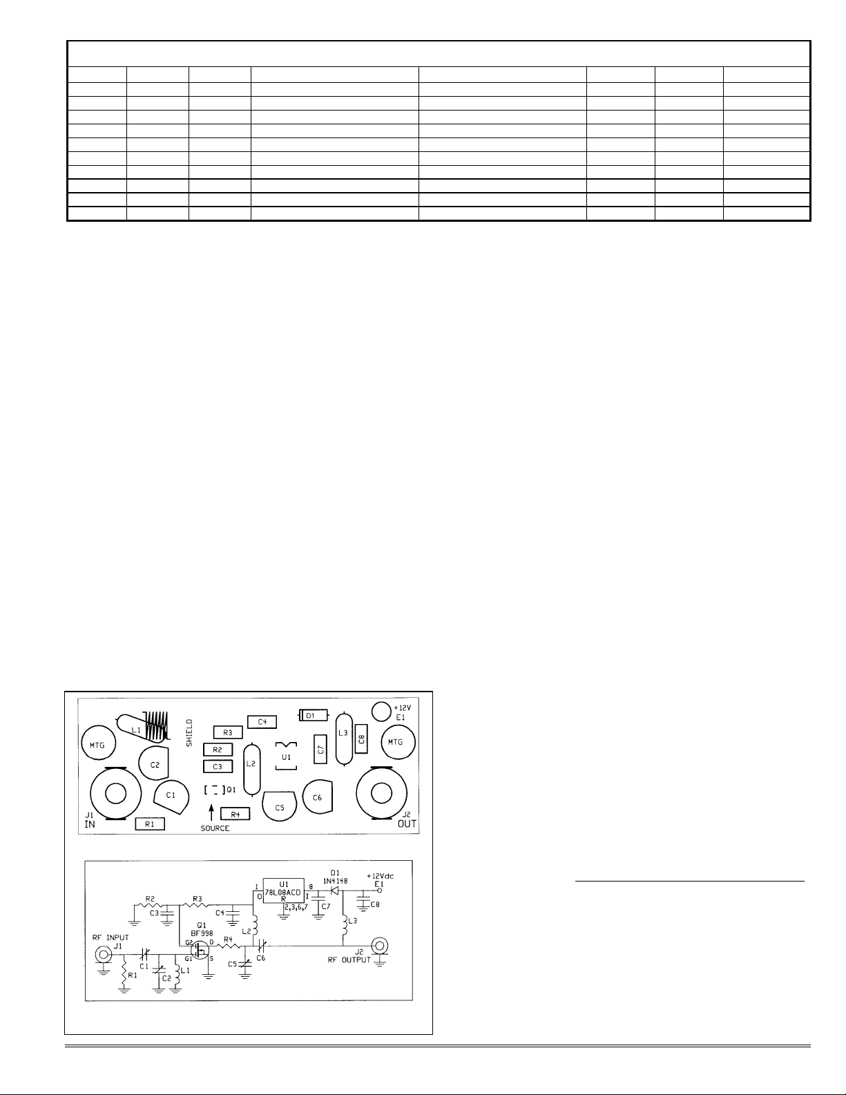
The LNY-( ) series of low-noise pre-
amps employs one of the new genera-
tion diode-protected dual-gate MOS
FET devices which are designed ex-
clusively for use in the vhf & uhf
bands. The 1 dB compression point
for these preamps is approximately
+5dBm. Surface mount technology is
used to obtain minimum noise figure
and best stability.
The preamp is connected in series
between the antenna and the receiver
to effectively lower the noise figure of
the receiver front end, allowing weaker
signals to be received. The LNY series
was designed for operation in 50 ohm
systems; however, they will operate
satisfactorily on 75 ohms as well.
INSTALLATION.
MOUNTING. The preamp can be
mounted to any flat surface with
standoffs and 4-40 screws through
the two mounting holes. The ideal
location is in the chassis with the re-
ceiver.
Complete shielding of the preamp
is not required. However, some care
should be given to selection of the
mounting location with regard to
feedback from adjacent receiver cir-
cuits or rf pickup if mounted very
close to a transmitter circuit. Because
the unit is small, make sure that it
isn't installed tight against the rf am-
plifier or first mixer of the receiver to
minimize feedback effects.
For best results, in a receiving sys-
tem when antenna is not also used for
transmit, preamp can be mounted
right at the antenna. Install the pre-
amp in a project box and mount the
box on a flat aluminum panel U-
bolted to the antenna mast. Then,
caulk around base of preamp and
around B+ and coax connectors to
weatherproof unit. Silicone sealant is
good for this purpose.
RF CONNECTIONS. Antenna and
receiver connections are made with
special rf type RCA plugs to the input
and output jacks on the preamp. The
RF INPUT must be connected to the
antenna, and the RF OUTPUT must
be connected to the receiver input.
CAUTION: The preamp cannot be
used on a transceiver unless you have
a way to connect it only in the receive
rf path.
Use good quality low-loss coax to
maintain low noise operation. Re-
member that any loss in coax from
antenna cannot be made up later in
the preamp; it adds directly to system
noise figure.
Note that special rf type RCA plugs
with good cable clamps are available
from us (model A5) as an accessory.
It is very important to use the proper
plugs and make sure the coax pigtails
soldered to the plugs are as short as
possible. Attempts to use a different
type of connector or to solder coax
directly to the board should be
avoided because it would degrade per-
formance.
POWER CONNECTIONS. Power
for the unit must be filtered +10 to 15
Vdc. Current drain is about 10 mA.
Solder positive supply wire to solder
pad E1 on the board. Many times,
the power supply ground connection
can be made through the coax shield.
Otherwise, connect a separate power
supply ground wire to the ground
plane on the pc board.
If you have a receiver which feeds
+12Vdc up the antenna cable to a
preamp, rf choke L3 can be added to
the LNY-( ) Preamp to allow power to
be taken from the coax. (This choke
is not supplied.) Note that such an
arrangement can affect the rf per-
formance of a preamp; so we recom-
mend you use a separate piece of
hookup wire to provide power when-
ever possible.
/
//
/CAUTION: Solid state amplifiers
can be damaged by large voltage tran-
sients and reverse polarity. Although
protection is provided in the preamp,
avoid such conditions as a matter of
principle. Special care should be
taken to install reverse transient ab-
sorbing diodes across any inductive
devices, such as relays. If the preamp
is connected to an antenna used for
transmit as well as receive, be sure
that the unit is connected only in the
receive path and that the coax relay
has sufficient isolation to avoid cou-
pling large amounts of rf to the pre-
amp.
HAMTRONICS® LNY-( ) RECEIVER PREAMP: INSTALLATION,
OPERATION, & MAINTENANCE
MODEL
TUNES RANGE
TYPICAL
NOISE FIG.
GAIN
MIN. 3DB
BANDWIDTH
LNY-28 24-37 MHz 0.6 dB 26 dB ±2 MHz
LNY-50 35-63 MHz 0.6 dB 24 dB ±3 MHz
LNY-100 88-108 MHz 0.6 dB 22 dB ±5 MHz
LNY-120 108-140 MHz 0.6dB 22 dB ±4 MHz
LNY-137 130-160 MHz 0.6 dB 18 dB ±4 MHz
LNY-146 130-160 MHz 0.6 dB 18 dB ±4 MHz
LNY-166 150-180 MHz 0.6 dB 16 dB ±5 MHz
LNY-220 195-240 MHz 0.7 dB 18 dB ±5 MHz
LNY-400 360-440 MHz 0.8 dB 19 dB ±5 MHz
LNY-450 400-470 MHz 0.8 dB 18 dB ±5 MHz
Note: Units are aligned to center of band.
WHEN DOES A PREAMP HELP?
It is tempting to hope that a pre-
amp can make any receiver more sen-
sitive in any situation. It is important
to understand what happens when
y
ou
add a preamp before a receiver.
A preamp can help overcome a defi-
ciency in receiver sensitivity
only
if
the noise figure is poor, either due to
the design or because a lossy filter
or cable adds to the noise figure.
For instance, a preamp up at the an-
tenna can overcome the effects of
coax cable loss.
However, adding gain in the front
end raises all signal levels; so, in ef-
fect, every dB of gain added over-
rides 1 dB of i-f selectivity or
dynamic range. Therefore, adding a
preamp can result in intermod or de-
sense. The only way to know is to try
it!
©1999 Hamtronics, Inc.; Hilton NY; USA. All ri
g
hts reserved. Hamtronics is a re
g
istered trademark. Revised: 4/22/03 - Pa
g
e 2 -
Figure 1. LNY Preamp, Parts Location and Schematic Diagrams
OPERATION.
The LNY series preamps operate in
linear mode; so they may be used to
receive any mode of transmission,
including ssb and atv.
Low-noise preamps are effective in
improving sensitivity of receivers in
weak signal areas. However, it is
normally considered inadvisable to
use a preamp, even with a well de-
signed receiver, in very strong signal
areas, such as the center of a large
city or other locations with high pow-
ered transmitters on all sorts of fre-
quencies.
Adding gain ahead of a receiver
degrades the selectivity of a receiver
by an equivalent amount by boosting
undesirable signals as well as desir-
able ones. In severe cases, strong
signals which do not cause intermod
by themselves will create intermod in
the rf stage or mixer of your receiver
after being amplified an additional
amount by the preamp.
If you use a preamp with a re-
peater receiver, you will need to have
additional rejection in your duplexer
to attenuate your transmit signal that
much more to prevent desense.
ALIGNMENT.
Units are factory aligned at the
center of the band, and they are easily
readjusted if your operating frequency
is near one end of the band or the
other instead of being near the center.
If retuning is necessary, simply retune
the variable capacitor(s) for best re-
ception of weak signals. No test
equipment is necessary. If you hap-
pen to have access to a signal genera-
tor and sinadder, they may be used;
otherwise, just do it by ear.
Note that for uhf units, it may be
necessary to spread the turns of the
coils to allow alignment for the high
end of the band. If the variable ca-
pacitors peak with the capacitor at
minimum capacitance (toward round
end of cap), spread the corresponding
coil turns to decrease inductance.
That should allow the variable capci-
tor to tune within its range.
The lower frequency units have
only one adjustment capacitor. The
higher frequency models have multi-
ple capacitors to tune; for those, al-
ternately adjust pairs of capacitors
seeking the best
combination of
settings.
TROUBLE-
SHOOTING.
Since the unit
is fairly simple,
troubleshooting
usually is limited
to checking the
dc voltages on the
transistor. These
will vary some-
what; but, in
general, the
source voltage
should be 0Vdc,
gate-2 should be
about 3.5 to
4Vdc, and the
drain should be
8Vdc. Current drain should be no
more than 20 mA (10mA typical).
The two common failure modes,
caused by excessive rf or dc voltage
transients, may cause the gate-2 volt-
age to be quite low or the same as the
drain of the transistor, indicating an
internal short. Generally, dc power
line problems, such as transients
cause a drain to gate-2 short and high
rf fields or lightning coming in the
antenna connector usually cause a
gate-1 to source short. The latter
usually doesn’t show up as a change
in dc voltage because gate-1 is con-
nected to dc ground in the circuit. A
sudden loss of sensitivity with no
change in dc voltage usually indicates
damage to the input gate (gate-1).
Note that the two gates have built-in
diode protection, but diodes will only
withstand a limited surge; beyond
that, the diodes will be damaged along
with the FET.
CAUTION: FET's are static sensi-
tive. If replacement is necessary, be
sure to ground your wrist before han-
dling them. Internal diode protection
will reduce, but not eliminate, risk.
Devices also are heat sensitive; so
don't apply soldering iron longer than
necessary. If FET is replaced, be sure
to orient as shown with the source
lead being the wide one.
Often times, the best way to re-
move surface mount devices from a
board are to cut the part up, removing
the leads individually and then unsol-
dering them.
PARTS LIST, COMMON
PARTS FOR ALL MODELS.
Ref # Value (marking)
C3,C4 .001 µf chip cap.
C7,C8 .001 µf chip cap.
D1 1N4148 diode
J1,J2 RCA jack (rf type)
Q1 Philips BF-998 MES FET
R1 620Ωchip resistor
R2, R3 86K chip resistor
R4 47Ωchip resistor
U1 78L08ACD voltage regul.
Parts List, Parts which change with Frequency Band.
Model C1 C2 L1 L2 C5 C6 L3 (option)
LNY-28 10pF disc 50pF var. 1µH 1µH n/u .001µF smt 1µH choke
LNY-50 10pF disc 50pF var. 0.33µH 0.33µH n/u 68pF smt 1µH choke
LNY-100 6pF disc 11pF var. 0.22µH 0.22µH n/u 68pF smt 0.33µH choke
LNY-120 4.5pF var. 11pF var. 6T #20 bus on ¼-20 screw form 0.33µH n/u .001µF smt 0.33µH choke
LNY-137 4.5pF var. 11pF var. 5T #20 bus on ¼-20 screw form 0.33µH n/u .001µF smt 0.33µH choke
LNY-146 4.5pF var. 11pF var. 5T #20 bus on ¼-20 screw form 0.33µH n/u .001µF smt 0.33µH choke
LNY-166 4.5pF var. 11pF var. 4T #20 bus on ¼-20 screw form 0.33µH n/u .001µF smt 0.33µH choke
LNY-220 4.5pF var 11pF var. 5T #20 bus on 8-18 screw form 0.33µH n/u .001µF smt 0.33µH choke
LNY-400 4.5pF var 4.5pF var 3T #20 bus 6-19 screw form 3T #20 bus 6-19 screw form 4.5pF var 4.5pF var 0.33µH choke
LNY-450 4.5pF var 4.5pF var 2T #20 bus 6-19 screw form 2T #20 bus 6-19 screw form 4.5pF var 4.5pF var 0.33µH choke

This manual suits for next models

10

Other HAMTRONICS Amplifier manuals

HAMTRONICS LNW-450 User manual

HAMTRONICS

HAMTRONICS LNW-450 User manual

HAMTRONICS LNW-144 User manual

HAMTRONICS

HAMTRONICS LNW-144 User manual

HAMTRONICS LPA 2-25R User manual

HAMTRONICS

HAMTRONICS LPA 2-25R User manual

HAMTRONICS LNW-28 User manual

HAMTRONICS

HAMTRONICS LNW-28 User manual

HAMTRONICS LPA 2-15R User manual

HAMTRONICS

HAMTRONICS LPA 2-15R User manual

HAMTRONICS RPA-402 Installation instructions

HAMTRONICS

HAMTRONICS RPA-402 Installation instructions

HAMTRONICS LNK Series Owner's manual

HAMTRONICS

HAMTRONICS LNK Series Owner's manual

HAMTRONICS LPA 4-10R User manual

HAMTRONICS

HAMTRONICS LPA 4-10R User manual

HAMTRONICS LPA 2-15 User manual

HAMTRONICS

HAMTRONICS LPA 2-15 User manual

HAMTRONICS LPA 2-25R Installation instructions

HAMTRONICS

HAMTRONICS LPA 2-25R Installation instructions

HAMTRONICS LPA 2-40 Installation guide

HAMTRONICS

HAMTRONICS LPA 2-40 Installation guide

HAMTRONICS RPA-30 Installation instructions

HAMTRONICS

HAMTRONICS RPA-30 Installation instructions

HAMTRONICS LPA 3-15R Maintenance and service guide

HAMTRONICS

HAMTRONICS LPA 3-15R Maintenance and service guide

HAMTRONICS RPA-302 Installation instructions

HAMTRONICS

HAMTRONICS RPA-302 Installation instructions

HAMTRONICS LPA 4-35 User manual

HAMTRONICS

HAMTRONICS LPA 4-35 User manual

Popular Amplifier manuals by other brands

Yamaha MLA8 Specifications

Yamaha

Yamaha MLA8 Specifications

VHT Lead 20 user manual

VHT

VHT Lead 20 user manual

Zzipp ZZONE200SA user manual

Zzipp

Zzipp ZZONE200SA user manual

Takstar E280 user manual

Takstar

Takstar E280 user manual

Onkyo A-905X instruction manual

Onkyo

Onkyo A-905X instruction manual

SKYTRONIC 103.153 instruction manual

SKYTRONIC

SKYTRONIC 103.153 instruction manual

AUSTRALIAN MONITOR AV2.2P Operation manual

AUSTRALIAN MONITOR

AUSTRALIAN MONITOR AV2.2P Operation manual

Canton Smart Amp 5.1 manual

Canton

Canton Smart Amp 5.1 manual

Cooper DCM 495 user guide

Cooper

Cooper DCM 495 user guide

Kenwood KAC-649S instruction manual

Kenwood

Kenwood KAC-649S instruction manual

Polk Audio PA400.1 owner's manual

Polk Audio

Polk Audio PA400.1 owner's manual

GAS MAD A1 user manual

GAS

GAS MAD A1 user manual

A&D Omniace RA2000 series instruction manual

A&D

A&D Omniace RA2000 series instruction manual

Televes AVANT9BASIC user guide

Televes

Televes AVANT9BASIC user guide

Laney LX20 user manual

Laney

Laney LX20 user manual

AXTON A642DSP Installation & operation manual

AXTON

AXTON A642DSP Installation & operation manual

Alpha 9500 HF operating manual

Alpha

Alpha 9500 HF operating manual

Sentry PR199 user manual

Sentry

Sentry PR199 user manual

manuals.online logo
manuals.online logoBrands
  • About & Mission
  • Contact us
  • Privacy Policy
  • Terms and Conditions

Copyright 2025 Manuals.Online. All Rights Reserved.