Sel M8100.0060 User manual

M8196-72E
Page 1 of 7
M8100 Synchroscope
User Manual
SELCO
Betonvej 11 - DK-4000 Roskilde
Denmark
Phone: 45 7026 1122 - Fax: 45 7026 2522
e-mail: [email protected]
Web site: www.selco.com

User Manual M8100
M8196-72E Page 2 of 7
Table of contents
1 Preface..........................................................................................................................................3
2 Function .......................................................................................................................................3
3 Connections..................................................................................................................................3
4 Adjustments .................................................................................................................................4
4.1 Check synchronizer relay.........................................................................................................4
4.2 Dead bus closure......................................................................................................................5
4.2.1 Voltage Offset..................................................................................................................5
4.2.2 Dead busbar delay time....................................................................................................5
5 Specifications...............................................................................................................................6
6 Type Selection Table ...................................................................................................................7

User Manual M8100
M8196-72E Page 3 of 7
1Preface
This manual describes the M8100 Synchroscope with built-in check synchronizer relay and dead
bus closure function.
2Function
The M8100 Synchroscope provides illuminated indication of the actual phase difference between
generator voltage and bus voltage. If the vector and the light spot turn clockwise, the generator
frequency is too high and must be reduced. The light spot turning anti clockwise indicates a lower
generator frequency, and consequently it must be increased.
In case the generator and busbar voltage and frequency and phase angle are within acceptable
limits, the built-in check synchronizer relay will activate. The limits of above parameters can be
adjusted by a potentiometer on the rear side of the unit.
For clearing of blackout situations the M8100 Synchroscope can be set up to connect a live
generator to a dead busbar (dead busbar closure function). When enabled, the M8100 Synchroscope
will give a close command to the generator breaker in case it detects that the busbar voltage is
below dead busbar voltage offset limit and the generator has reached at least 80% of its nominal
voltage. The busbar must be dead during the entire dead busbar delay time (this time delay is also
adjustable). The purpose of the dead busbar voltage offset is to give room for possible noise on the
busbar voltage input of M8100 Synchroscope.
Warning: As this function could lead to short circuits (e.g. when more than one generator are
connecting to a dead busbar at the same time, this function should be treated carefully.
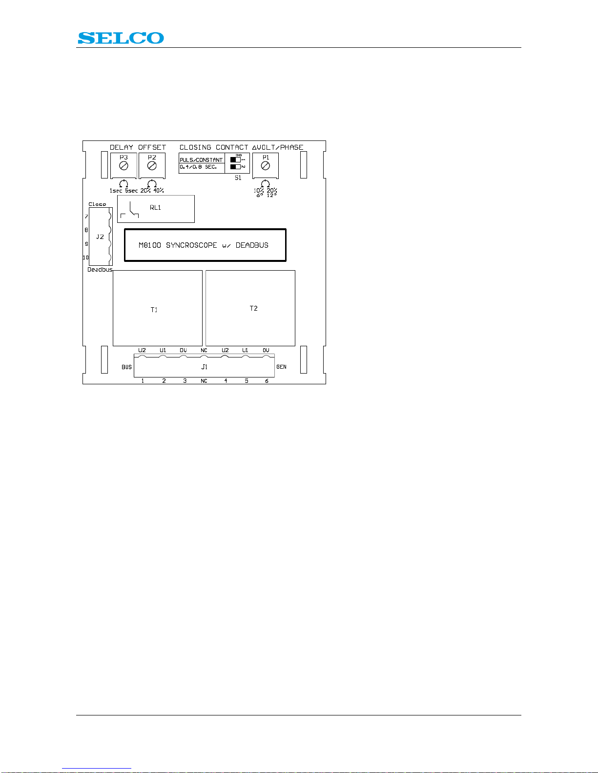
3Connections
Before commissioning, make sure that the
phase sequences of generator and busbar
connections are correct.

User Manual M8100
M8196-72E Page 4 of 7
4Adjustments
On the rear side of the unit are a number of potentiometers and DIP switches for programming of
the unit:
4.1 Check synchronizer relay
On DIP switch S1 pin 1 the check synchronizer relay can be programmed to offer a constant closing
signal that remains activated as long as voltage-, frequency-, and phase difference between
generator and busbar voltage are within limits for automatic closure, or a pulse signal of 0,4 or 0,8s.
S1, pin1 OFF, pulse signal
S1, pin1 ON, constant signal
In case S1, pin1 is in OFF position, S1, pin2 can be used for programming the length of the closing
pulse:
S1, pin 2 OFF, closing pulse of 0,4s
S1, pin 2 ON, closing pulse of 0,8s
On potentiometer P1 the acceptable limits for voltage-, frequency- and phase deviation can be
adjusted. It is a combined setting on one potentiometer. Narrowest limits are adjusted by turning P1
counter clockwise until end position. Then the limits are as follows:
∆U = 10%
∆f = 0,15Hz
∆φ = 6◦

User Manual M8100
M8196-72E Page 5 of 7
The highest tolerance is adjusted by turning the potentiometer P1 clockwise until end position.
Then the limits are as follows:
∆U = 20%
∆f = 0,3Hz
∆φ = 12◦
4.2 Dead bus closure
This function enables the built-in check synchronizer relay to close the circuit breaker even though
there is no voltage on the busbar. The generator voltage must be at least at 80% of the nominal
voltage before the dead bus closure can activate.
For activating the dead bus closure, terminals 9 and 10 must be bridged.
4.2.1 Voltage Offset
The purpose of the dead busbar voltage offset is to give room for possible noise on the busbar
voltage input of M8100 Synchroscope.
The M8100 Synchroscope considers the busbar to be dead in case the busbar voltage is below the
dead busbar voltage offset. This offset can be adjusted by potentiometer P2. The range is between
20% of nominal voltage to 40% of nominal voltage.
Turning P2 counter clockwise until end position means 20%.
Turning P2 clockwise until end position means 40%.
4.2.2 Dead busbar delay time
The dead bus closure facility will only close the breaker to the dead busbar in case the busbar
voltage has been below the voltage offset limit during the entire time delay. This time delay can be
adjusted by potentiometer P3.
Turning P3 counter clockwise to end position: delay = 1s
Turning P3 clockwise to end position: delay = 5s

User Manual M8100
M8196-72E Page 6 of 7
5Specifications
Max. Voltage 660V
Voltage range 70 - 110%
Consumption 2x 3VA max.
Frequency range 35 - 70Hz
Pull in / drop out diff. frequency ±9Hz
Operating temperature -20°C to +70°C
EMC CE according to EN50081-1, EN50082-1,
EN50081-2, EN50082-2
Approvals Certified by major classification societies
Burn-in 50 hours before final test
Enclosure material Flame retardant
Weight 0.7kg
Dimensions 96 x 96 x 80mm (H x W x D)
Panel cut out 92 x 92mm (H x W)
Check sync. relay
Voltage difference 10 - 20%
Frequency difference 0.15 - 0.3Hz Combined setting
Phase difference 6 - 12°
Dead bus delay 1s –5s
Dead bus voltage offset 20% - 40%
Min. generator voltage for DB closure 80% of nominal voltage
Contact rating AC: 250V, 1.2A, 125VA
DC: 30V, 1A, 30W
The specifications are subject to change without notice.

User Manual M8100
M8196-72E Page 7 of 7
6Type Selection Table
Terminals
1-3 2-3
Type 4-6 5-6 Function
M8100.0050 450V 400V With check synchronizer relay
M8100.0060 230V With check synchronizer relay
M8100.0070 480V 415V With check synchronizer relay
M8100.0080 110V 100V With check synchronizer relay
Other voltages on request.
This manual suits for next models
3
Table of contents
Other Sel Control Unit manuals
Popular Control Unit manuals by other brands

Pfeiffer Vacuum
Pfeiffer Vacuum EVB 063 PA instruction sheet

Visonic
Visonic PowerMax Pro GSM installation instructions

Spirax Sarco
Spirax Sarco HP70 Series Installation and maintenance instructions

PLX Devices
PLX Devices DM-100 quick start guide

Sony
Sony FCB-IX47 instruction manual

DIEL
DIEL ME 100 V3 Installation and instruction manual