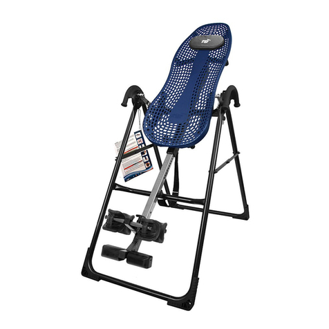
Hang ups ComforTrak EP-560 User manual

ComforTrakTM Series
Assembly Instructions
EP-560, EP-860, EP-960 & EP-970 Models
*Inversion Table images may
vary slightly from your model.
The EP-560 is shown here.

IMPORTANT SAFETY INSTRUCTIONS
READ ALL INSTRUCTIONS BEFORE USING THE INVERSION TABLE.
WARNING
!
SAVE THESE INSTRUCTIONS
WARNING - To reduce the risk of injury to persons:
5HDGDQGXQGHUVWDQGDOOWKHLQVWUXFWLRQVYLHZWKHLQVWUXFWLRQDOYLGHRUHYLHZDOORWKHUDFFRPSDQ\LQJGRFXPHQWVDQGLQVSHFWWKH
equipment before using the inversion table. It is your responsibility to familiarize yourself with the proper use of this equipment and the
LQKHUHQWULVNVRILQYHUVLRQVXFKDVIDOOLQJRQ\RXUKHDGRUQHFNSLQFKLQJHQWUDSPHQWRUHTXLSPHQWIDLOXUH,WLVWKHUHVSRQVLELOLW\RI
the owner to ensure that all users of the product are fully informed about the proper use of the equipment and all safety precautions.
&ORVHVXSHUYLVLRQLVQHFHVVDU\ZKHQWKHLQYHUVLRQWDEOHLVXVHGQHDUFKLOGUHQRUE\RUQHDULQYDOLGVRUGLVDEOHGSHUVRQV
8VHWKHLQYHUVLRQWDEOHRQO\IRULWVLQWHQGHGXVHDVGHVFULEHGLQWKLVPDQXDODO NOT use attachments not recommended by the
manufacturer.
NEVER drop or insert any object into any opening.
DO NOT use or store product outdoors.
DO NOT use if you are over 6 ft 6 in (198 cm) or over 300 lbs. (136 kg). Structural failure could occur or head/neck may impact the
ÀRRUGXULQJLQYHUVLRQ
DO NOT allow children to use this machine.
.HHSFKLOGUHQE\VWDQGHUVDQGSHWVDZD\IURPPDFKLQHZKLOHLQXVH
.HHSERG\SDUWVKDLUORRVHFORWKLQJDQGMHZHOU\FOHDURIDOOPRYLQJSDUWV
7KHLQYHUVLRQWDEOHKDVQRXVHUVHUYLFHDEOHSDUWV
7KLVSURGXFWLVLQWHQGHGIRULQGRRUKRPHXVHRQO\ DO NOT XVHLQDQ\FRPPHUFLDOUHQWDORULQVWLWXWLRQDOVHWWLQJ
FAILURE TO FOLLOW INSTRUCTIONS AND WARNINGS COULD RESULT IN SERIOUS INJURY OR DEATH.
BEFORE YOU BEGIN: Review all steps before beginning assembly and read all precautions before using the inversion table.
Carefully adhere to the Assembly Instructions and Owner’s Manual to help ensure safety and product integrity.

IMPORTANT SAFETY INSTRUCTIONS
READ ALL INSTRUCTIONS BEFORE USING THE INVERSION TABLE.
WARNING
!
SAVE THESE INSTRUCTIONS
FAILURE TO FOLLOW INSTRUCTIONS AND WARNINGS COULD RESULT IN SERIOUS INJURY OR DEATH.
BEFORE YOU BEGIN: Review all steps before beginning assembly and read all precautions before using the inversion table.
Carefully adhere to the Assembly Instructions and Owner’s Manual to help ensure safety and product integrity.
DO NOTXVHWKHHTXLSPHQWZLWKRXWDOLFHQVHGSK\VLFLDQ¶VDSSURYDODQGDUHYLHZRIWKHPHGLFDOFRQWUDLQGLFDWLRQVDVQRWHGLQWKH
Owner’s Manual.
)DLOXUHWRDVVHPEOHDQGRUXVHWKHHTXLSPHQWDVGLUHFWHGPD\YRLGWKHPDQXIDFWXUHU¶VZDUUDQW\RQWKLVSURGXFWDQGFRXOGUHVXOWLQ
injury or death.
&KRRVHDOHYHOVXUIDFHIRUDVVHPEOLQJDQGRSHUDWLQJWKHWDEOH
)ROORZHDFKVWHSLQVHTXHQFHDO NOT skip ahead.
0DNHVXUHWKDWDOOIDVWHQHUVDUHVHFXUH
ALWAYS test and inspect the table. Make sure the table rotates smoothly to inverted position and back.
ALWAYS replace defective components immediately and/or keep the equipment out of use until repair.

E6-1600
Items for Assembly
F5-1088 F5-1130IA-1149
F5-1048
H1-3007
F5-1089
F5-1064
A-Frame
Angle Tether (EP-560 models)
EZ-AngleTM Tether (EP-860, EP-960, EP-970)
Stability Feet (2) May come pre-assembled
Screws (2)
Table Bed
Upper Bed Portion
Lower Bed Portion & Frame
Head Pillow
Bolts & Nuts (3)
ComforTrakTM Bed Frame Extension
Main Shaft with EZ-ReachTM Ankle Lock System
(for EP-960 model only)
Main Shaft with Deluxe EZ-ReachTM Ankle Lock
System
(for EP-970 model only)
E6-1100
F5-1007
F5-1008
F7-1033
E1-1002
E6-1300A
E6-1300B
E6-1105
F1-1390
E6-1380
E6-1630
NX-1630B
ITEMS FOR ASSEMBLY ITEM NUMBER
Main Shaft with T-Pin Ankle Lock System
(for EP-560 models, EP-860 only)
Rear Ankle Bar
Rear Heel Cup (one pre-assembled, one separate)
Rubber Plug (1)
Bolt/Nut (1)
Screw (1)
Front Ankle Bar
Bolt (1)
Nut (1)
End Cap (1)
Ankle Comfort Dial Bar
Ankle Comfort Dials (2) (one pre-assembled, one separate)
Screw (1)
E6-1600
IA-1113
EP-1054
F5-1056
F5-1087
H1-1200
EP-1045B
F5-1089
H1-3007
F5-1048
IA-1119
IA-1118
IA-1123
ITEMS FOR ASSEMBLY ITEM NUMBER
Handle Assembly
Strech AssistTM Handles (2) (EP-560 models only)
Strech MaxTM Handles (2) (EP-860, EP-960, EP-970)
Bolts & Nuts (2) (EP-860, EP-960, EP-970 ONLY)
Allen Head Screws (4) May come pre-assembled
Roller Hinge Assembly
3-Hole Roller Hinges (2) (EP-560, EP-560 Ltd. EP-860)
Traction Handle 3-Hole Roller Hinges (2)
(EP-560 Sport, EP-960, EP-970)
Tools
10/13mm Wrenches (2)
Packaged with the Roller HInge Assembly
5mm Allen Wrench
Screwdriver
E6-1500
E6-1520
H1-1209
F5-0071
F5-1064
TR-1003
F5-1088
IA-1149
F5-1130
ITEMS FOR ASSEMBLY ITEM NUMBER
EP-1105
This column is ONLY for the Assembly of the
Main Shaft with T-Pin Ankle Lock System (E6-1600)
H1-1209 F5-0071E6-1500 E6-1520
TR-1003
E6-1630 NX-1630B
IA-1123IA-1119
IA-1118
EP-1045B
F5-1087 H1-1200
E6-1100
F5-1007
F5-1008
F7-1033 E1-1002
IA-1113
EP-1054
F5-1056
Items are not shown to scale.
E6-1300B
E6-1300A F1-1390
E6-1380
E6-1105


9
13
10
7
8
3
11
14
4
6
12
2
1
5
*Inversion Table images may
vary slightly from your model.
The EP-560 is shown here.
%HIRUHUHDGLQJIXUWKHUVWXG\WKHGUDZLQJEHORZWRIDPLOLDUL]H\RXUVHOIZLWK
the important components of your new Teeter Hang Ups®inversion table.
What Model Do You Own?
Head Pillow
Bed Frame Extension
ComforTrak™ Table Bed
3-Hole Roller Hinges
Handles
Height-Selector Locking Pin
Spreader Arms
1
2
3
4
5
6
7
Important: Please locate the model of your
Teeter inversion table before assembly.
7KHPRGHOFDQEHIRXQGRQ$WKHH[WHULRURIWKHER[
or B) the serial label located on the back of the table bed.
My Serial Number:
__________________
Don’t forget to register your
warranty at teeter-inversion.com
BEFORE BEGINNING
Angle Tether
Crossbar
A-Frame
Main Shaft
Ankle Lock System
Ankle Comfort Dial™
Stability Feet
8
9
10
11
12
13
14

WARNING LABEL PLACEMENT
Important: Please review all labels and supporting materials before using your inversion table.
We hope you enjoy your new Teeter Hang Ups Inversion Table!
If you have any questions, please contact our Customer Service Department at 1.800.847.0143 or www.teeter-inversion.com.
This drawing indicates the locations
of the warning labels found on your product.
,IDODEHOLVPLVVLQJLOOHJLEOHRULVUHPRYHG
contact Customer Service at the phone number or
website found at the bottom of this page to request a
complimentary replacement label.
Note: Image and labels below not shown at actual size.

Step 1
Assemble the front Stability Feet (F7-1033) onto the A-Frame (E6-1100)
Feet may come pre-assembled.
/D\WKH$)UDPHRQWKHIORRUZLWKWKH&URVVEDURQWKHWRSVLGH)LJXUHWRDVVHPEOH
the front Stability Feet.
6HOHFWWKH6WDELOLW\)RRWODEHOHG1XPEHURQWKHLQVLGHDQGSODFHLWRQWKH5,*+7VLGHRI
WKH$)UDPH,QVHUWWZRRIWKH6FUHZV(RQHWKURXJKWKHVLGHDQGRQHWKURXJKWKH
bottom (Figure 2). Tighten using the Screwdriver (F5-1130) provided.
5HSHDWZLWKWKH6WDELOLW\)RRWODEHOHG1XPEHURQWKH/()7VLGH)LJXUH
3RVLWLRQWKH$)UDPHRQLWVIHHWDQGRSHQLWVRWKH6SUHDGHU$UPVDUHORFNHG)LJXUH
)DPLOLDUL]H\RXUVHOIZLWKWKH)URQW%DFN/HIWDQG5LJKWRIWKH$)UDPH<RXPD\ZDQWWR
refer back to this diagram for reference throughout the assembly process.
Back
Front
2
1
Right Left
Crossbar
2
Spreader Arms
1
Right
Left
FIGURE 1
FIGURE 2
FIGURE 3

Step 2
EP-560, EP-560 Sport & EP-560 Limited Models
Depending on the model you have purchased, the items in this step will vary.
See “Which Model Do you Own?” (page 4) for more information.
Assemble the Handles to the Table Bed (EP-1300)
Bolts/Nuts may come pre-assembled in the Handles. Simply unscrew to remove.
EP-560 models: Assemble the Stretch Assist Handles (E6-1500)
3ODFHHDFK+DQGOHOHIWULJKWRYHUWKHRXWVLGHHGJHRIWKHFRUUHVSRQGLQJ+LQJH3ODWH
7KHKDQGOHVDUHVWDPSHGZLWKDQ³/´IRU/HIWDQGDQ³5´IRU5LJKWWKLVFDQEHIRXQGRQWKH
interior of the handle (Figure 4).
,QVHUWWKUHH$OOHQ+HDG%ROWV)WKURXJKWKH+LQJH3ODWHLQWRHDFK+DQGOH)LJXUH
$7LJKWHQZLWKWKH$OOHQ:UHQFKSURYLGHGEHLQJFDUHIXOQRWWRRYHUWLJKWHQ
FIGURE 4
FIGURE 4A

Step 2
EP-860, EP-960, EP-970 Models
Assemble the Handles to the Table Bed (EP-1300)
Bolts/Nuts may come pre-assembled in the Handles. Simply unscrew to remove.
EP-860, EP-960 & EP-970: Assemble the Stretch Max Handles (E6-1520)
$VVHPEOHRQHVLGHDWDWLPH,WGRHVQRWPDWWHUZKLFKVLGHOHIWULJKW\RXVWDUWZLWK
8VLQJWKHPP:UHQFK)UHPRYHWKH%ROW1XWDQGWKUHH:DVKHUVIURPZKHUH
WKH6SUHDGHU$UPPHHWVWKHUHDURIWKH$)UDPH)LJXUH'LVFDUGWKH%ROWDQG1XWEXW
keep one of the Washers.
3ODFHWKHFRUUHVSRQGLQJ+DQGOHOHIWULJKWRYHUWKHRXWVLGHHGJHRIWKH+LQJH3ODWHUHIHU
to Figure 6).
,QVHUWDQGORRVHO\KDQGWLJKWHQWKHWKUHH$OOHQ+HDG%ROWV)WKURXJKWKH+LQJH
Plate into the handle (Figure 6).
3RVLWLRQWKHORZHUSDUWRIWKH+DQGOHEHWZHHQWKH6SUHDGHU$UPDQGWKH$)UDPHOHJ
Thread one Washer on the Bolt and insert from the inside of the A-Frame. Make sure the
%ROWJRHVWKURXJKWKH$)UDPHOHJ+DQGOHDQG6SUHDGHU$UP7KUHDGRQH:DVKHURQWKH
end and secure with the Nut (Figure 6). Refer to Figure 6A for how the finished assembly of
this should look.
)XOO\WLJKWHQDOO%ROWVXVLQJWKH$OOHQ:UHQFKSURYLGHGEHLQJFDUHIXOQRWWRRYHUWLJKWHQ
5HSHDWRQWKHRWKHUVLGH
FIGURE 5
FIGURE 6
FIGURE 6A
(continued)

Step 3
Depending on the model you have purchased, the items in this step will vary.
See “Which Model Do you Own?” (page 4) for more information.
EP-560 models & EP-860: Complete this step.
EP-560 Sport: Complete this step to use the standard Ankle Lock System. To use with the
EZ-Up Gravity Boots refer to either the ComforTrak DVD or the insert that can be found with
the Conversio Bar.
EP-960 & EP-970: Skip this step and proceed directly to Step 4.
Assemble the T-Pin Ankle Lock System onto the Main Shaft (E6-1600)
Install the Ankle Comfort Dial
6OLGHWKH$QNOH&RPIRUW'LDO%DU,$ZLWKSUHDVVHPEOHG$QNOH&RPIRUW'LDOLQWRWKH
hole at the front base of the Main Shaft (Figure 7).
7KH$QNOH&RPIRUW'LDOLVGHVLJQHGZLWKD+LJKDQG/RZVHWWLQJ3RVLWLRQWKHSUHDVVHPEOHG
Dial in the Low Setting (screw holes facing up) for ease of assembly. Slide the separate
Ankle Comfort Dial (IA-1118) onto the Ankle Comfort Dial Bar.
,QVHUWWKH6FUHZ,$)LJXUH$DQGWLJKWHQZLWKWKH6FUHZGULYHU)SURYLGHG
See Figure 7B for detailed view of Screw (IA-1123).
NOTE: Refer to the Owner’s Manual for a complete description of the Ankle Comfort Dial
settings.
FIGURE 7
FIGURE 7A
FIGURE 7B

Step 3
Install the Rear Ankle Bar Assembly
:LWKWKHWZRULGJHVRIWKHSUHDVVHPEOHG+HHO&XSRQWKHERWWRPLQVHUWWKH5HDU$QNOH%DU
(IA-1113) into the large hole at the back of the Main Shaft (Figure 8).
,QVHUWWKH%ROW)IURPWKHUHDURIWKH0DLQ6KDIWWRVHFXUHWKH5HDU$QNOH%DU
)LJXUHDQGIDVWHQZLWKWKH:DVKHUDQG1XWXVLQJWKHZUHQFKHVSURYLGHG
6OLGHWKHVHSDUDWH+HHO&XS(3ZLWKWKHWZRULGJHVRQWKHERWWRPRQWRWKHRSHQ
end of the Rear Ankle Bar (Figure 8A).
TIP: To assist with assembly, repeatedly rotate the Heel Cup while pushing it onto the Rear
Ankle Bar.
$OLJQWKHSUHGULOOHGKROHVRIWKH5XEEHU3OXJZLWKWKHKROHVLQWKH5HDU$QNOH%DU,QVHUWWKH
Rubber Plug (F5-1056) into the open end of the Rear Ankle Bar (Figure 9).
TIP: You may want to use a rubber mallet to assist with assembly.
6HFXUHWKH5XEEHU3OXJZLWKWKH6FUHZ+XVLQJWKH6FUHZGULYHU)SURYLGHG
)LJXUH$,IWKH6FUHZGRHVQRWWLJKWHQHDVLO\\RXPD\QHHGWRUHSRVLWLRQWKHDOLJQPHQWRI
the Rubber Plug.
(continued)
FIGURE 9
FIGURE 9A
1 Ridge
2 Ridges
FIGURE 8
FIGURE 8A

Step 3
Install the Front Ankle Bar Assembly
:LWKKROHVHWWLQJVIDFLQJXSLQVHUWWKH)URQW$QNOH%DU(3%LQWRWKH)URQW$QNOH%DU
Housing (Figure 10). Pull up on the T-Pin Lock to allow the Front Ankle Bar to insert all the
way into the housing. Release the T-Pin to engage in the hole setting closest to the Front
Ankle Cups.
)URPWKHUHYHUVHVLGHSXOORQWKH]LSWLHWRVWUHWFKWKH5HWDLQHU6SULQJDQG&DEOH/RRSVR
that they align with the holes in the back of the Front Ankle Bar Housing (Figure 11).
,QVHUWWKH%ROW)VWDUWLQJWKURXJKWKHRXWHUVLGHRIWKHKRXVLQJLQWKHIROORZLQJRUGHU
KROH5HWDLQHU6SULQJDQG&DEOH/RRSKROH)LJXUH
7LJKWHQWKH1XW+XVLQJWKHPP2SHQ:UHQFK)SURYLGHG
&XWWKHORQJSRUWLRQRIWKH]LSWLHZLWKVFLVVRUV)LJXUH$VRWKDWLWGRHVQ¶WLQWHUIHUHZLWK
the function of the Retainer Spring. Cover the open end with the End Cap (F5-1048)
(Figure 11B).
WARNING
!
Failure to assemble the T-Pin Ankle Lock System properly could
result in serious injury or death!
Retainer Spring & Cable Loop
1
1
FIGURE 11
FIGURE 11A
FIGURE 11B
(continued)
1
Front Ankle Bar Housing
1
FIGURE 10

Step 4
Assemble the Table Bed (E6-1300) and Bed Frame Extension (E6-1380)
NOTE: This assembly will be referred to as Table Bed (E6-1300) for the remainder of the
Assembly Instructions.
/RFDWHWKHIROORZLQJLWHPVWRDVVHPEOHWKH7DEOH%HG
ComforTrak™ Bed - Upper Portion (E6-1300A) ComforTrak™ Bed Frame (E6-1300)
Bed Frame Extension (E6-1380) Bolts & Nuts (F1-1390)
5mm Allen Wrench (IA-1149) 10/13mm Wrench (F5-1088)
/D\WKH&RPIRU7UDN%HG8SSHU3RUWLRQ($IDFHGRZQRQWKHIORRU
3ODFHWKH&RPIRU7UDN%HG)UDPH(IDFHGRZQRQWRSRIWKH8SSHU3RUWLRQ
and align the bolt holes.
5HDFKLQJXQGHUQHDWKLQVHUWD%ROWLQWKHFHQWHUKROHDQGKDQGWLJKWHQZLWKD1XW
(Figure 12).
5HDFKLQJXQGHUQHDWKLQVHUWRQHRIWKHUHPDLQLQJ%ROWVWKURXJKRQHRIWKHKROHVLQWKH
Upper Portion and hold in place. Slide one of the Bed Frame Extension loops over the
Bolt and hand-tighten with a Nut (Figure 13).
5HSHDWZLWKUHPDLQLQJVLGH)LJXUH
7RIXOO\WLJKWHQDOOWKUHHQXWVWRWKHEROWVLQVHUWWKHPP$OOHQ:UHQFK,$LQWR
the Bolt heads and tighten the Nuts using the 10/13mm Wrench (F5-1088).
Center Bolt (1)
Upper Bolts/Nuts (2)
1
1
Bed Frame Extension - Loop
FIGURE 12
FIGURE 14
FIGURE 13

Step 5
Depending on the model you have purchased, the items in this step will vary.
See “Which Model Do you Own?” (page 4) for more information.
Assemble the Roller Hinges to the Table Bed (EP-1300)
EP-560, EP-560 Ltd. & EP-860: Use 3-Hole Roller Hinges (F5-1064)
EP-560 Sport, EP-950 & EP-970: Use 3-Hole Roller Hinges with Traction Handles (TR-
1003)
)RUHDVHRIDVVHPEO\UHVWWKH7DEOH%HGDJDLQVWWKH&URVVEDU)LJXUH
2SHQWKH&DP/RFNVRQHDFKVLGHRIWKH7DEOH%HG)LJXUH
:LWKWKH3LYRW3LQVIDFLQJRXWZDUGLQVHUWWKH5ROOHU+LQJHVLQWRWKHEUDFNHWVRQHDFKVLGH
of the Table Bed Assembly. The Roller Hinges must slide between the Cam Locks and the
Brackets (Figure 16).
(QJDJHRQHRIWKHKROHVLQWKH5ROOHU+LQJHRYHUWKH%UDFNHW3LQ0DNHVXUHWKH5ROOHU
Hinges are in the same hole setting on both sides. Figure 17 shows the Roller Hinges
HQJDJHGFRUUHFWO\ZLWKWKH%UDFNHW3LQHQJDJHGLQ6HWWLQJ&
3XVKGRZQRQWKH&DP/RFNV)LJXUHWRVHFXUHWKH5ROOHU+LQJHV
NOTE: Refer to the Owner’s Manual for an explanation of the hole settings.
If you are unsure, use Setting C to start.
Cam Lock
2
Pivot Pin
1
12
Unlocked Locked
CBA
FIGURE 15
FIGURE 16
FIGURE 17
FIGURE 18
Bracket Pin
1
1
WARNING
!
NEVER disassemble the Roller Hinge.

Step 6
Attach the Table Bed (E6-1300) to the A-Frame (E6-1100)
3LFNXSWKH7DEOH%HGKROGLQJHDFKVLGHQHDUWKH5ROOHU+LQJHVDQGVWDQGLQIURQWRIWKH
A-Frame where the Crossbar is located (refer to Figure 3 to determine A-Frame Front).
/RZHUHDFK5ROOHU+LQJH3LYRW3LQLQWRWKH$)UDPHKLQJHSODWHVRQHVLGHDWDWLPH
)LJXUHVDQG$:LWKSUHVVXUHWKH6HOI/RFNLQJ+RRNVZLOORSHQWRDOORZWKH3LYRW3LQ
LQWRWKHVORWWKHQDXWRPDWLFDOO\FORVHRYHUWKH3LYRW3LQ
NOTE: You may need to push outward on the A-Frame in order for the 2nd Pivot Pin
to lock in place.
0DNHVXUHWKDWHDFK3LYRW3LQLVVHDWHGDWWKHEDVHRIWKHVORWRIWKH+LQJH3ODWH)LJXUH
WKDWWKH6HOI/RFNLQJ+RRNVKDYHFORVHGRYHUERWK3LYRW3LQVDQGWKDWWKH7DEOH
Bed rotates smoothly.
WARNING
!
Failure of the Self-Locking Hooks to close over both Roller Hinge
Pivot Pins is an indication of improper assembly and if not corrected
could result in serious injury or death!
2Self-Locking Hook
Roller Hinge Pivot Pin
1
2
Self-Locking Hook
1
Roller Hinge
2
2
1
1
FIGURE 19
FIGURE 19A
FIGURE 20

Step 7
Depending on the model you have purchased, the items in this step will vary.
See “Which Model Do you Own?” (page 4) for more information.
Insert the Main Shaft into the Table Bed
EP-560 and EP-860 models will use the Main Shaft with T-Pin Ankle Lock System (E6-1600)
EP-960 model will use the EZ-Reach Ratchet Ankle Lock System (E6-1630)
EP-970 model will use the Deluxe EZ-Reach Ratchet Ankle Lock System (NX-1630B)
:LWKWKH+HLJKW$GMXVWPHQW6HWWLQJVRQWKH0DLQ6KDIWIDFLQJXSVOLGHWKHHQGRIWKH
Main Shaft into the Main Shaft Housing (Figure 21) on the Table Bed.
3XOORXWWKH+HLJKW6HOHFWRU/RFNLQJ3LQWRDOORZWKH0DLQ6KDIWWRVOLGHLQIXUWKHUDQGUHOHDVH
in the desired height setting. Refer to the Owner’s Manual for more information on selecting
your height setting.
7KH0DLQ6KDIWMUST REST against the Crossbar of the A-Frame (Figure 22).
NOTE: The Crossbar prevents the Table Bed from rotating forward when the user steps
on the Ankle Comfort Dial. If the Main Shaft does not rest on the Crossbar as shown in
Figure 23, then the Table Bed has been assembled backwards onto the A-Frame.
This MUST BE CORRECTED before use.
Main Shaft
Main Shaft Housing
Height-Selector Locking Pin
2
3
1
Crossbar
1Proper Resting Position
2
FRONT
1
23
1
2
FIGURE 21
FIGURE 22

We hope you enjoy your new Teeter Hang Ups Inversion Table!
If you have any questions, please contact our Customer Service Department at 1.800.847.0143 or www.teeter-inversion.com.
Image B
Go back to Step 6 for instruction.
Demonstrates that the Table Bed has been assembled
into the A-Frame backwards and must be corrected.
Image A
Go back to Step 5 for instruction
Demonstrates that the Roller Hinges have been assembled
upside down into the Table Bed and must be corrected.
WARNING
!
,I\RXU7HHWHU+DQJ8SV,QYHUVLRQ7DEOHORRNVOLNHHLWKHURIWKHVHLPDJHV\RXUWDEOHKDVEHHQPLVDVVHPEOHGDQGLVXQILWIRUXVH
Improper assembly could result in serious injury or death!

Step 8
Depending on the model you have purchased, the items in this step will vary.
See “Which Model Do you Own?” (page 4) for more information.
Assemble the Tether to the Table Bed (EP-1300)
EP-560 & EP-560 Sport: use the Angle Tether (F5-1007)
EP-860, EP-960 & EP-970: use the EZ-Angle Tether (F5-1008)
7KH7HWKHUZLOOFRPHSUHDVVHPEOHGWRWKH$)UDPH
8QIROGWKHDGMXVWDEOH7HWKHUDQGFOLSLWWRWKH8%DURQWKHXQGHUVLGHRIWKH7DEOH%HG
(Figure 23).
7KH(=$QJOH7HWKHUKDVFRORUFRGHGDQJOHVWRDVVLVWLQYDULHGDQJOHVRILQYHUVLRQIRU
your experience level:
20° / Gentle Inversion
Green stripe must show in the center of the sliding buckle.
40°/ Moderate Inversion
Orange stripe must show in the center of the sliding buckle.
60° / Intermediate Inversion
Red stripe must show in the center of the sliding buckle.
This is the angle when full decompression is realized.
90° / Advanced Inversion
Remove the tether strap clip from U-Bar to enable rotation to full inversion.
FIGURE 23

Step 9
Attach the Head Pillow (EP-1105)
$WWDFKWKH+HDG3LOORZE\VHFXULQJWKH9HOFUR6WUDSVWKURXJKWKHKROHVLQWKH7DEOH%HG
(Figure 24). The position of the pillow can be adjusted depending on the user.
Attach the Owner’s Maunal
The Owner’s Manual contains important information on how to use your Teeter Hang Ups, including how
to personalize the user settings, properly secure and release the Ankle Lock System, and test and adjust
the rotation control.
,IQRWDOUHDG\DWWDFKHGWKUHDGWKHSURYLGHGPHWDOFKDLQSURYLGHGWKURXJKWKHSUHSXQFKHG
hole in the upper corner of the Owner’s Manual.
6HFXUHWKHFKDLQWRWKH$)UDPHWKURXJKWKHGHVLJQDWHGKROHLQWKH+,QJH3ODWH)LJXUH
Allow the Owner’s Manual to hang freely on the outside of the A-Frame Spread Arms so it
doesn’t interfere with the rotation of the Table Bed.
IMPORTANT: Do not remove the Owner’s Manual. It should remain permanently attached
to the A-Frame of your inversion table to serve as a reference for proper adjustment and
use of the equipment.
Before Use
7HVWWKH,QYHUVLRQ7DEOHE\KDQGIRUVPRRWKDQGVWHDG\URWDWLRQ)LJXUHDQGWKDWDOO
fasteners are secure.
3OHDVHFRPSOHWHWKHZDUUDQW\UHJLVWUDWLRQRQOLQHDWZZZWHHWHULQYHUVLRQFRP
WARNING
!
Read the Owner’s Manual thoroughly before using your Teeter Hang Ups
Inversion Table. Improper settings could result in serious injury or death!
FIGURE 25
FIGURE 24
This manual suits for next models
3
Table of contents
Other Hang ups Fitness Equipment manuals
