Hans Pausch COSMOS-2 User manual
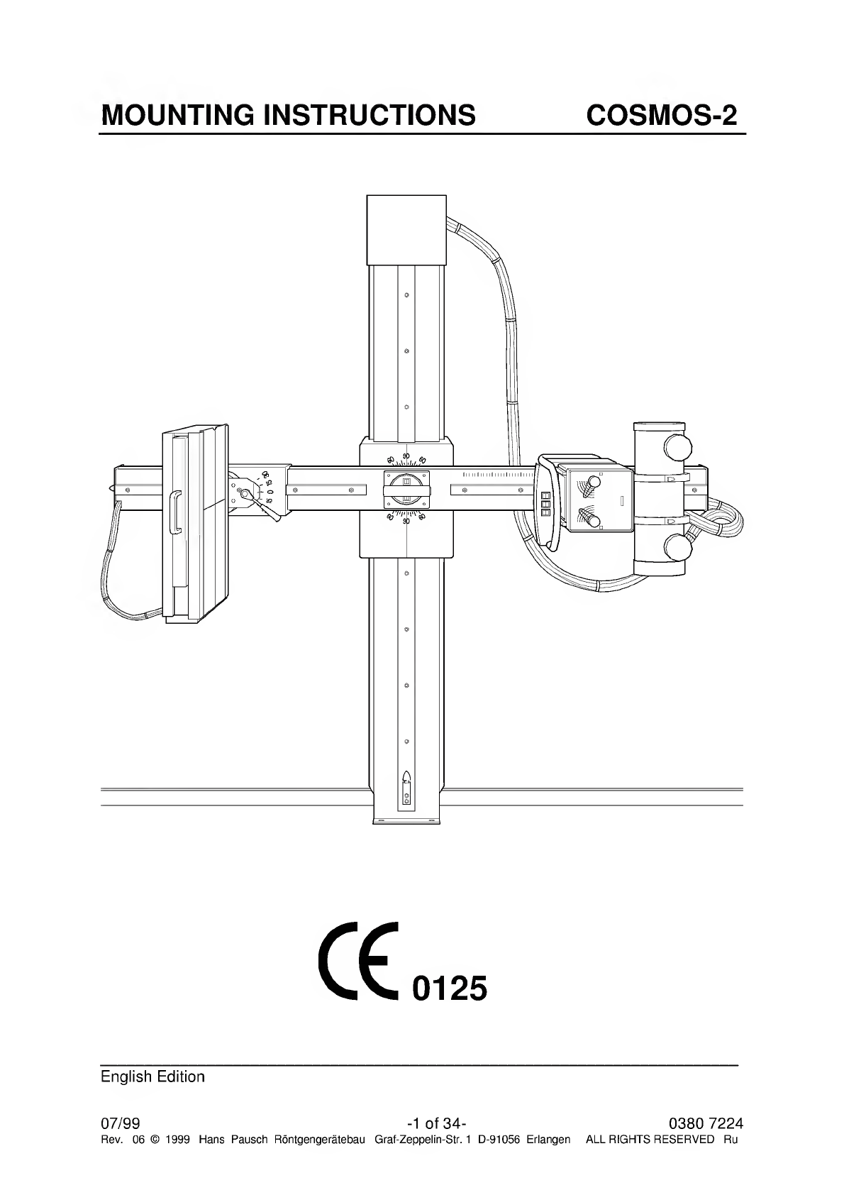
MOUNTING
INSTRUCTIONS
COSMOS-2
0125
English
Edition
07/99
-1
of
34-
0380
7224
Rev.
06
©
1999
Hans
Pausch
Rontgengeratebau
Graf-Zeppelin-Str.
1
D-91056
Erlangen
ALL
RIGHTS
RESERVED
Ru

TABLE
OF
CONTENTS
Page
1
.
Specification
1.1
General
Safety
Notes
3
1.2.
Weight
of
Components
3
1.3.
Dimensions
of
Components
3
1.4
Shipping
Weight
and
Dimensions
3
1.5
Component
Designation
4
1.6.
Dimensional
Drawings
5
1.7
Power
Connection
6
1.8
Special
Tools
Required
6
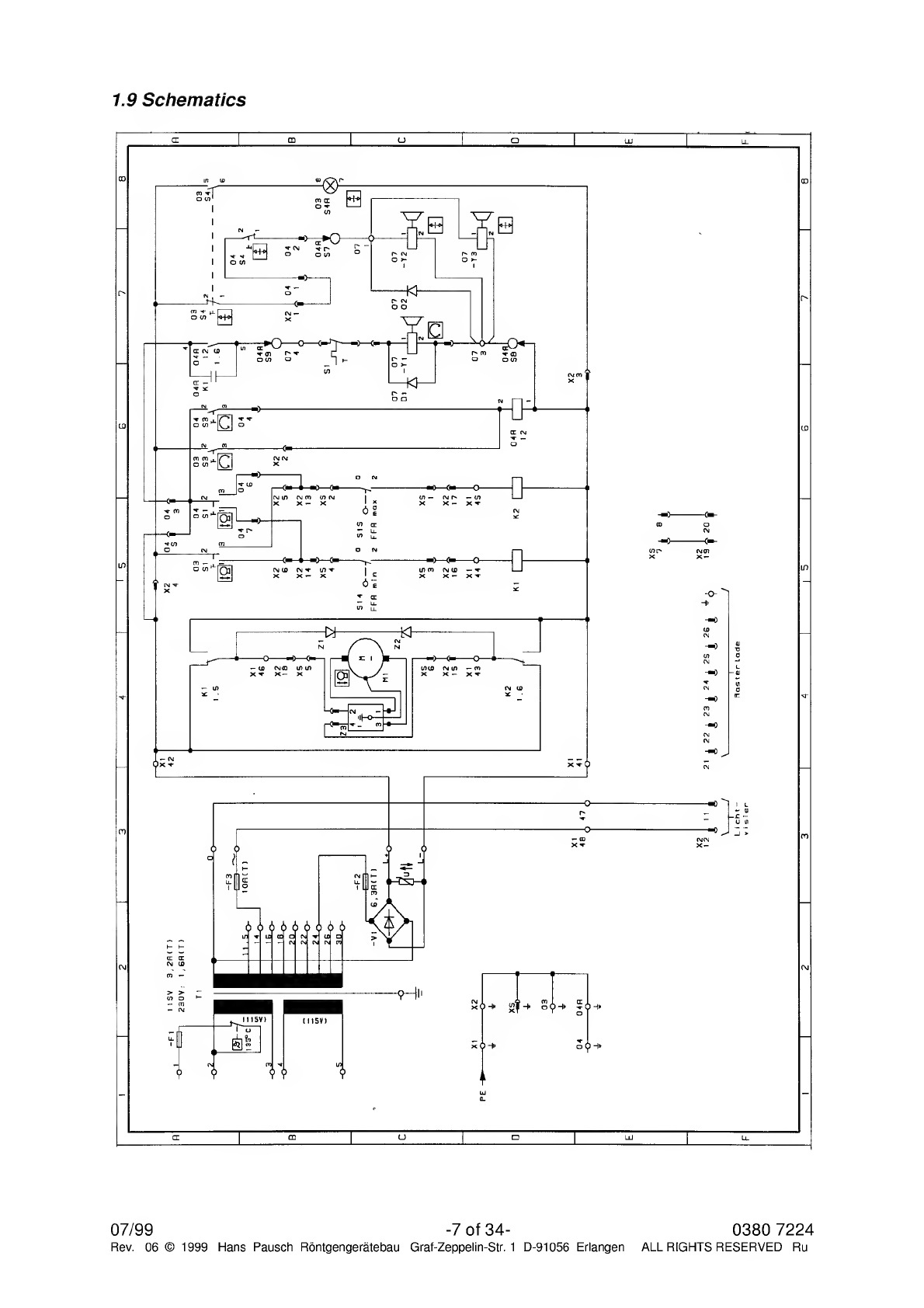
1.9.
Schematics
7
1.10
Wiring
Diagram
8
1.11
Physical
Location
of
Electrical
Components
9
1.12
Component
Numbers
and
Designation
9
1.13
Component
check
list
10
2.
Mounting
of
Unit
2.1
Site
Preparation
11
2.2
Uncrating
11
2.3
Unit
preparation
12
2.4
Unit
mounting
2.5
Leveling
the
unit
13
2.5.1
Loading
of
counter
weights
14
2.6
Mounting
of
Bucky
Support
14
2.7
Mounting
of
Controls
14
2.8
Mounting
of
X-Ray
Tube
and
Collimator
14
2.9
Mounting
of
Bucky
15
2.10
Release
the
vertical
drive
15
2.11
Electrical
Connections
16
3.
Adjustments
3.1
Bucky
Tilt
Adjustment
17
3.2
Adjustment
of
Rotation
17
3.3
Adjustment
of
Vertical
Movement
17
3.4
Adjustment
of
Rotational
Lock
18
3.5
Vertical
Lock
18
3.6
SID-Pointer
18
3.7
SID-Drive
Clutch
19
3.8
SID
End
Switch
19
4.0
4.1
Technical
Maintenance
Mechanical
and
Electrical
Checks
21
4.2
Functional
Checks
25
4.3
Spare
Parts
26
4.4
Spare
Parts
List
28
4.5
Name
Plate
Location
32
4.6
Maintenance
documentation
33
0380
7224
-
2
of
34
-
Rev.
06
©
1999
Hans
Pausch
Rontgengeratebau
Graf-Zeppelin-Str.
1
D-91056
Erlangen
12
07/99
ALL
RIGHTS
RESERVED
Ru
1
.
Specifications
1.1.
General
Safety
Notes
In
the
Federal
Republic
of
Germany,
the
electrical
installation
of
rooms
used
for
medical
purposes
must
conform
to
the
provisions
of
VDE
Standard
0107.
Consult
installation
lay¬
out
plan.
During
installation
it
is
important
that
all
protective
ground
wire
connections
provided
by
the
manufacturer
properly
made
before
the
equipment
is
started
up.
The
pro¬
tective
ground
wires
between
the
individual
system
components
and
the
power
supply
are
connected
as
shown
in
the
wiring
diagram.
Regulations
of
professional
associations
concerning
safety
and
accident
prevention
must
be
observed.
No
work
may
be
performed
on
parts
carrying
a
voltage
higher
than
42V
(Peak
Voltage).
If
it
is
necessary
to
turn
on
the
power
for
execution
of
movements
of
the
equipment
in
the
mode
of
installation
procedure,
it
must
be
shut
down
immediately
after
completion
of
these
movements.
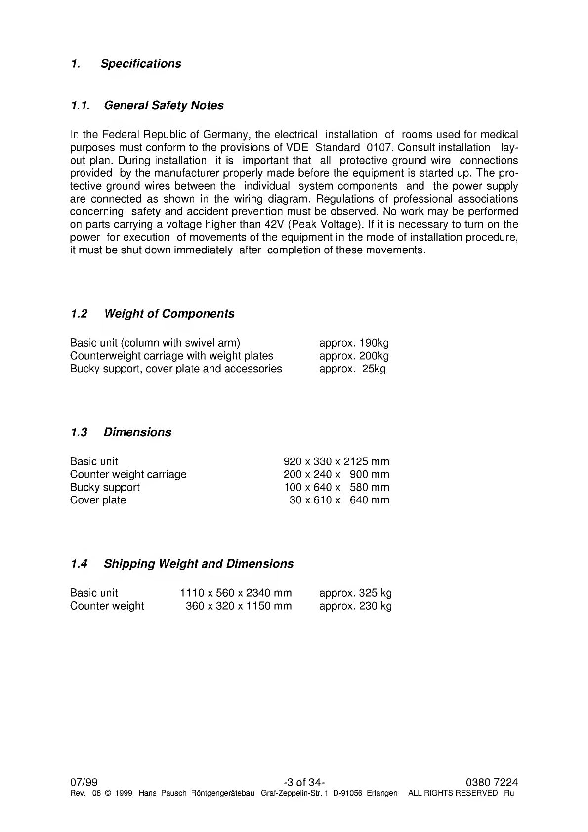
1.2
Weight
of
Components
Basic
unit
(column
with
swivel
arm)
Counterweight
carriage
with
weight
plates
Bucky
support,
cover
plate
and
accessories
approx.
190kg
approx.
200kg
approx.
25kg
1.3
Dimensions
Basic
unit
920
x
330
x
2125
mm
Counter
weight
carriage
200
x
240
x
900
mm
Bucky
support
100
x
640
x
580
mm
Cover
plate
30
x
610
x
640
mm
1.4
Shipping
Weight
and
Dimensions
Basic
unit
1110
x
560
x
2340
mm
Counter
weight
360
x
320
x
1150
mm
approx.
325
kg
approx.
230
kg
07/99
-3
of
34-
Rev.
06
©
1999
Hans
Pausch
Rontgengeratebau
Graf-Zeppelin-Str.
1
D-91056
Erlangen
0380
7224
ALL
RIGHTS
RESERVED
Ru
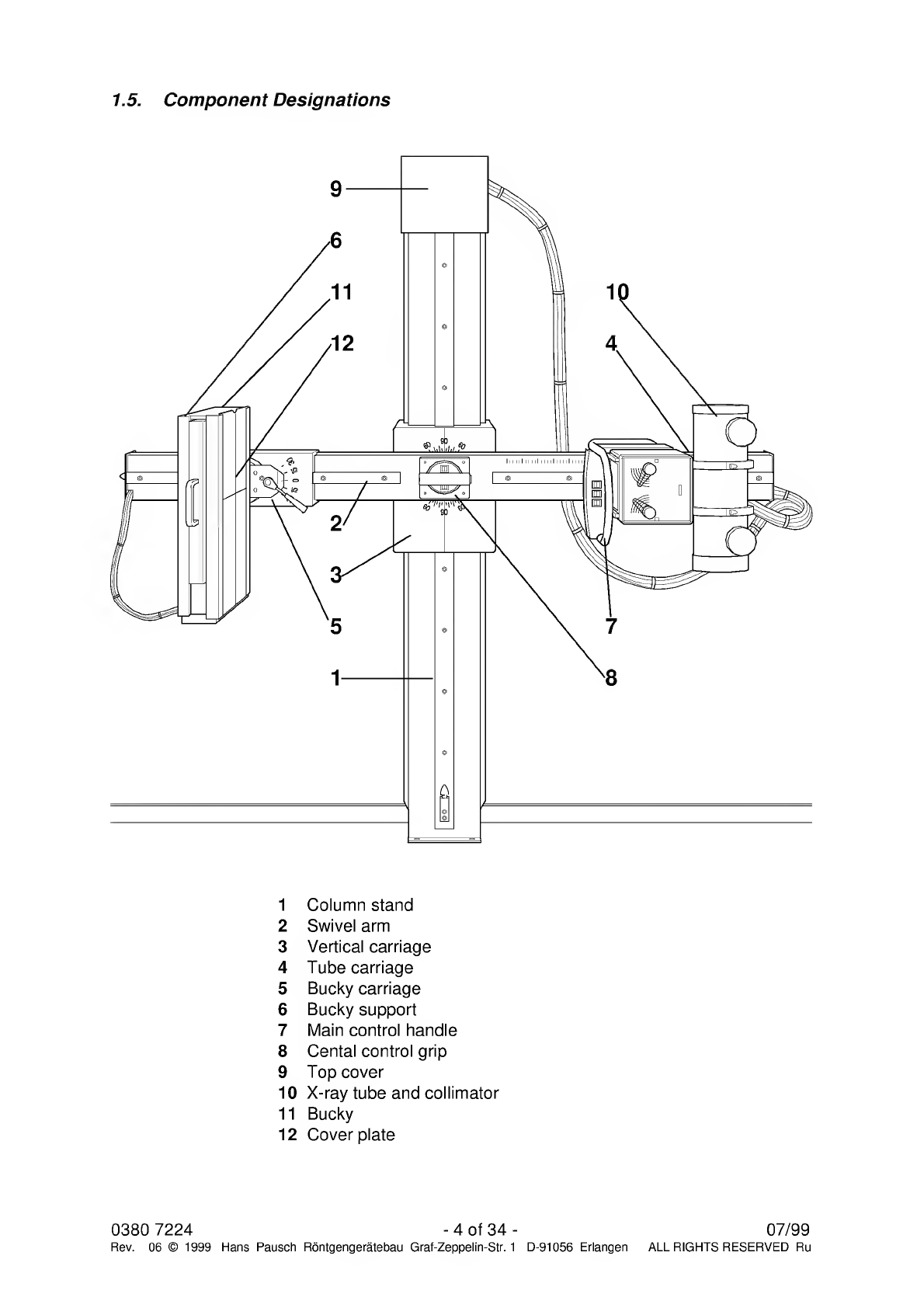
1.5.
Component
Designations
1
Column
stand
2
Swivel
arm
3
Vertical
carriage
4
Tube
carriage
5
Bucky
carriage
6
Bucky
support
7
Main
control
handle
8
Cental
control
grip
9
Top
cover
10
X-ray
tube
and
collimator
11
Bucky
12
Cover
plate
0380
7224
-
4
of
34
-
07/99
Rev.
06
©
1999
Hans
Pausch
Rontgengeratebau
Graf-Zeppelin-Str.
1
D-91056
Erlangen
ALL
RIGHTS
RESERVED
Ru

min.
440
*10
-
max.
1635
*ftf
ca.
2850
*
07/99
-5
of
34-
Rev.
06
©
1999
Hans
Pausch
Rontgengeratebau
Graf-Zeppelin-Str.
1
D-91056
Erlangen
I_I
0380
7224
ALL
RIGHTS
RESERVED
Ru

1.7
Power
Connection
Requirement:
At
the
beginning
of
mounting
the
unit
all
electrical
connections
and
in¬
stallations
must
been
carried
out
according
to
the
ordering
contract
about
voltage
and
frequency.
Nominal
voltage:
Frequency:
Nominal
current:
Power
ratings:
115/230
VAC
50/60
Hz
2
/1
slow
blow
fuse
230
VA
1.8
Special
Tools
and
Measuring
Instruments
Required
Machinist's
water
level
Masonry
drill,
12
mm
(.472")
diameter
1
spring
scale
200
N
0380
7224
-
6
of
34
-
07/99
Rev.
06
©
1999
Hans
Pausch
Rontgengeratebau
Graf-Zeppelin-Str.
1
D-91056
Erlangen
ALL
RIGHTS
RESERVED
Ru
07/99
-7
of
34-
0380
7224
Rev.
06
©
1999
Hans
Pausch
Rontgengeratebau
Graf-Zeppelin-Str.
1
D-91056
Erlangen
ALL
RIGHTS
RESERVED
Ru

1.10
Wiring
Diagram
0380
7224
Rev.
06
©
1999
-
8
of
34
-
Hans
Pausch
Rontgengeratebau
Graf-Zeppelin-Str.
1
D-91056
Erlangen
07/99
ALL
RIGHTS
RESERVED
Ru

1.11
Physical
Location
of
Electrical
Components
Component
Numbers
and
Designation
XI
Power
supply
X2
Terminal
strip
03
Main
control
handle
04
Cental
control
grip
X5
SID
drive
07
vertical
carriage
07/99
-9
of
34-
0380
7224
Rev.
06
©
1999
Hans
Pausch
Rontgengeratebau
Graf-Zeppelin-Str.
1
D-91056
Erlangen
ALL
RIGHTS
RESERVED
Ru
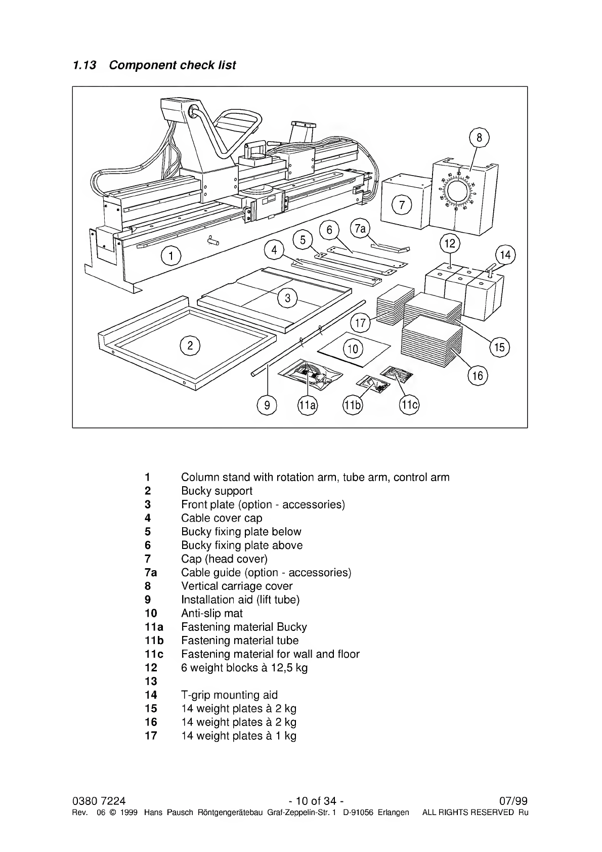
1.13
Component
check
list
1
Column
stand
with
rotation
arm,
tube
arm,
control
arm
2
Bucky
support
3
Front
plate
(option
-
accessories)
4
Cable
cover
cap
5
Bucky
fixing
plate
below
6
Bucky
fixing
plate
above
7
Cap
(head
cover)
7a
Cable
guide
(option
-
accessories)
8
Vertical
carriage
cover
9
Installation
aid
(lift
tube)
10
Anti-slip
mat
11a
Fastening
material
Bucky
11b
Fastening
material
tube
11c
Fastening
material
for
wall
and
floor
12
6
weight
blocks
a
12,5
kg
13
14
T-grip
mounting
aid
15
14
weight
plates
a
2
kg
16
14
weight
plates
a
2
kg
17
14
weight
plates
a
1
kg
0380
7224
-
10
of
34
-
07/99
Rev.
06
©
1999
Hans
Pausch
Rontgengeratebau
Graf-Zeppelin-Str.
1
D-91056
Erlangen
ALL
RIGHTS
RESERVED
Ru

2
.
Mounting
of
Unit
2.1
Site
Preparation
Make
unit
site
preparation
according
to
dimensional
drawing
on
page
5.The
bore
diameter
must
be
12
mm.
To
assure
all
movements
of
the
equipment
pay
attention
to
all
movement
possibilities.
Note:
The
mounting
points
must
be
suitable
for
tensile
strength
of
1000
N
pull.
For
example:
Liebig-safety
bolts
SI
2/65
for
concrete
floor
tensile
strength
classification
DIN
1045
B
15.
2.2
Uncrating
Remove
top
and
side
walls
of
the
crate
(not
necessary
with
just
protection
packing).
Take
out
the
Bucky
support
and
accessories
and
unpack
completely.
Check
the
contents
of
each
box
with
dispatch
note
or
order
to
assure
that
all
items
are
located.
Pay
also
attention
to
page
10
1.13
Component
check
list.
Fig.
1
Fig.
2
Mount
low
voltage
unit
(Fig.
27)
onto
the
rope
return
block
with
the
four
stay
bolts.
Move
equipment
with
the
transport
palette
to
the
installation
place
and
assure
that
foot
end
of
the
palette
is
approx.
1,5
m
away
from
the
installation
wall.
07/99
-11
of
34-
0380
7224
Rev.
06
©
1999
Hans
Pausch
Rontgengeratebau
Graf-Zeppelin-Str.
1
D-91056
Erlangen
ALL
RIGHTS
RESERVED
Ru
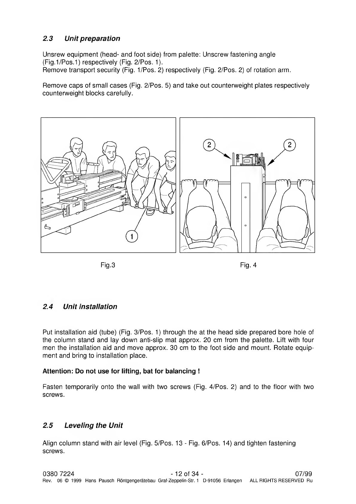
2.3
U
nit
preparation
Unsrew
equipment
(head-
and
foot
side)
from
palette:
Unscrew
fastening
angle
(Fig.l/Pos.1)
respectively
(Fig.
2/Pos.
1).
Remove
transport
security
(Fig.
1/Pos.
2)
respectively
(Fig.
2/Pos.
2)
of
rotation
arm.
Remove
caps
of
small
cases
(Fig.
2/Pos.
5)
and
take
out
counterweight
plates
respectively
counterweight
blocks
carefully.
Fig.3
Fig.
4
2.4
U
nit
installation
Put
installation
aid
(tube)
(Fig.
3/Pos.
1)
through
the
at
the
head
side
prepared
bore
hole
of
the
column
stand
and
lay
down
anti-slip
mat
approx.
20
cm
from
the
palette.
Lift
with
four
men
the
installation
aid
and
move
approx.
30
cm
to
the
foot
side
and
mount.
Rotate
equip¬
ment
and
bring
to
installation
place.
Attention:
Do
not
use
for
lifting,
bat
for
balancing
!
Fasten
temporarily
onto
the
wall
with
two
screws
(Fig.
4/Pos.
2)
and
to
the
floor
with
two
screws.
2.5
L
eveling
the
Unit
Align
column
stand
with
air
level
(Fig.
5/Pos.
13
-
Fig.
6/Pos.
14)
and
tighten
fastening
screws.
0380
7224
-
12
of
34
-
07/99
Rev.
06
©
1999
Hans
Pausch
Rontgengeratebau
Graf-Zeppelin-Str.
1
D-91056
Erlangen
ALL
RIGHTS
RESERVED
Ru

2.5.1
Loading
of
counterweights
Remove
cover
(Fig.
8/Pos.
18)
from
column
stand
and
strap
(Pos.
19)
from
counter
weight
carriage.
Insert
counter
weight
blocks
(Fig.
7/Pos.
19)
with
screwed
in
support
grip
(Pos.
20)
in
counter
weight
carriage.
Attention:
Insert
on
three
levels
2
counter
weight
blocks
each
and
7
counter
weight
plates
each.
Fig.
7
Fig.
8
07/99
-13
of
34-
0380
7224
Rev.
06
©
1999
Hans
Pausch
Rontgengeratebau
Graf-Zeppelin-Str.
1
D-91056
Erlangen
ALL
RIGHTS
RESERVED
Ru

The
adjustment
will
be
done
with
counter
balance
plates.
Ref.
to
section
3.3
Mount
strap
(Fig.
8/Pos.
19)
on
counter
weight
carriage
and
reinstall
cover
(Pos.18).
2.6
M
ounting
of
Bucky
Support
Put
swivel
arm
in
upright
position,
so
that
the
Bucky
carriage
(Fig.
10/
Pos.
27)
is
at
the
bottom
(Fig.
10/Pos.
28).
Mount
Bucky
support
(Pos.
27)
and
lining
plate
(Pos.
28a)
with
4
screws
to
Bucky
carriage
(Pos.
28).
Fig.
9
Fig.
10
2.7
M
ounting
of
Control
arm
Release
the
rotation
brake
while
pushing
onto
the
armature
(Fig.
9/Pos.
30)
and
rotate
rota¬
tion
arm
about
90°carefully.
Dismount
cover
(Fig.
11/Pos.
31+29)
from
the
tube
support
(Pos.
32).
Dismount
control
arm
(Pos.
33)
and
remount
again
180°
rotated.
2.8
M
ounting
of
X-Ray
Tube
and
Collimator
Lift
rotation
brake
while
pushing
onto
the
armature
(Fig.
9/Pos.
30)
and
rotate
rotation
arm
carefully
by
90°.
Bring
tube
(Fig.
11/Pos.
34)
to
the
tube
support
(Pos.
32)
and
fasten
with
4
screws.
Put
collimator
(Pos.
36)
onto
the
tube
(Pos.
34)
and
fasten.
Rotate
again
rotation
arm
by
180°.
Attention:
The
weight
counterbalance
of
the
rotation
arm
is
not
counterbalanced.
There
is
a
risk
of
accident!
0380
7224
-
14
of
34
-
07/99
Rev.
06
©
1999
Hans
Pausch
Rontgengeratebau
Graf-Zeppelin-Str.
1
D-91056
Erlangen
ALL
RIGHTS
RESERVED
Ru
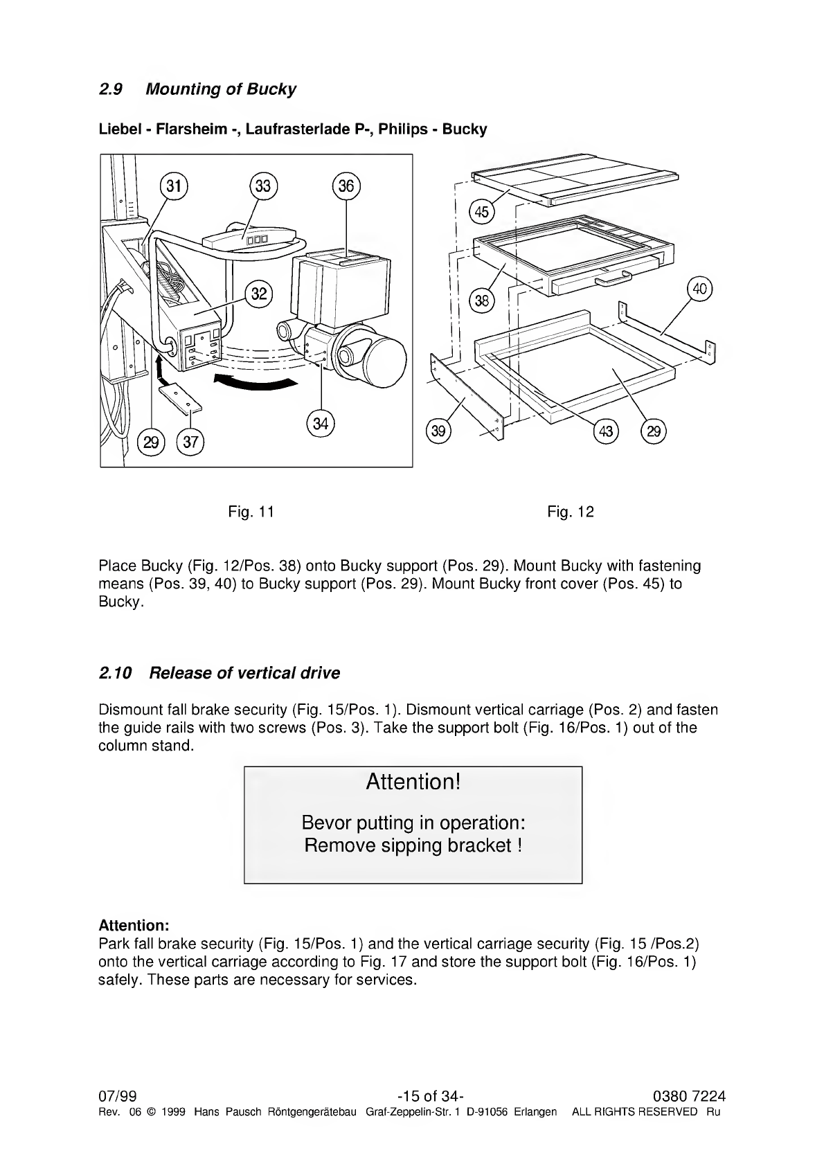
2.9
Mounting
of
Bucky
Liebel
-
Flarsheim
Laufrasterlade
P-,
Philips
-
Bucky
Fig.
11
Fig.
12
Place
Bucky
(Fig.
12/Pos.
38)
onto
Bucky
support
(Pos.
29).
Mount
Bucky
with
fastening
means
(Pos.
39,
40)
to
Bucky
support
(Pos.
29).
Mount
Bucky
front
cover
(Pos.
45)
to
Bucky.
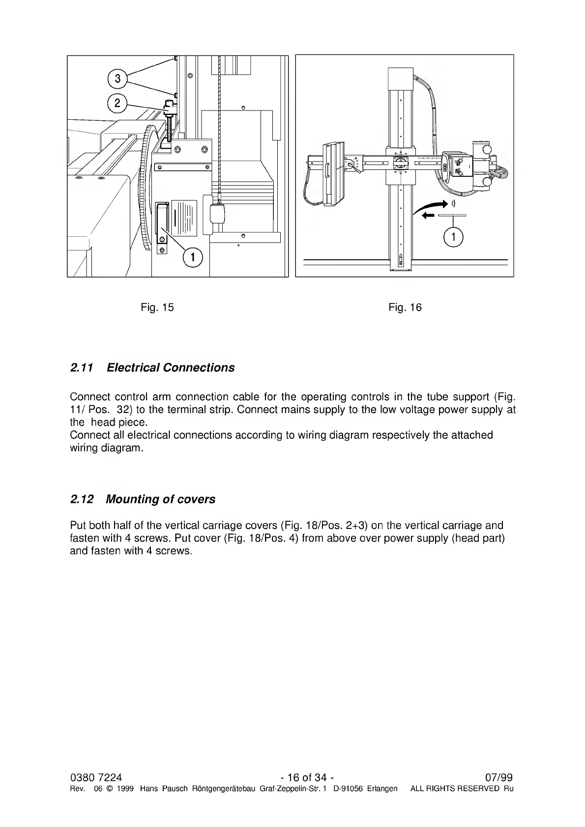
2.10
Release
of
vertical
drive
Dismount
fall
brake
security
(Fig.
15/Pos.
1).
Dismount
vertical
carriage
(Pos.
2)
and
fasten
the
guide
rails
with
two
screws
(Pos.
3).
Take
the
support
bolt
(Fig.
16/Pos.
1)
out
of
the
column
stand.
Attention!
Bevor
putting
in
operation:
Remove
sipping
bracket!
Attention:
Park
fall
brake
security
(Fig.
15/Pos.
1)
and
the
vertical
carriage
security
(Fig.
15
/Pos.2)
onto
the
vertical
carriage
according
to
Fig.
17
and
store
the
support
bolt
(Fig.
16/Pos.
1)
safely.
These
parts
are
necessary
for
services.
07/99
-15
of
34-
0380
7224
Rev.
06
©
1999
Hans
Pausch
Rontgengeratebau
Graf-Zeppelin-Str.
1
D-91056
Erlangen
ALL
RIGHTS
RESERVED
Ru
2.11
Electrical
Connections
Connect
control
arm
connection
cable
for
the
operating
controls
in
the
tube
support
(Fig.
11/
Pos.
32)
to
the
terminal
strip.
Connect
mains
supply
to
the
low
voltage
power
supply
at
the
head
piece.
Connect
all
electrical
connections
according
to
wiring
diagram
respectively
the
attached
wiring
diagram.
2.12
Mounting
of
covers
Put
both
half
of
the
vertical
carriage
covers
(Fig.
18/Pos.
2+3)
on
the
vertical
carriage
and
fasten
with
4
screws.
Put
cover
(Fig.
18/Pos.
4)
from
above
over
power
supply
(head
part)
and
fasten
with
4
screws.
0380
7224
-
16
of
34
-
07/99
Rev.
06
©
1999
Hans
Pausch
Rontgengeratebau
Graf-Zeppelin-Str.
1
D-91056
Erlangen
ALL
RIGHTS
RESERVED
Ru
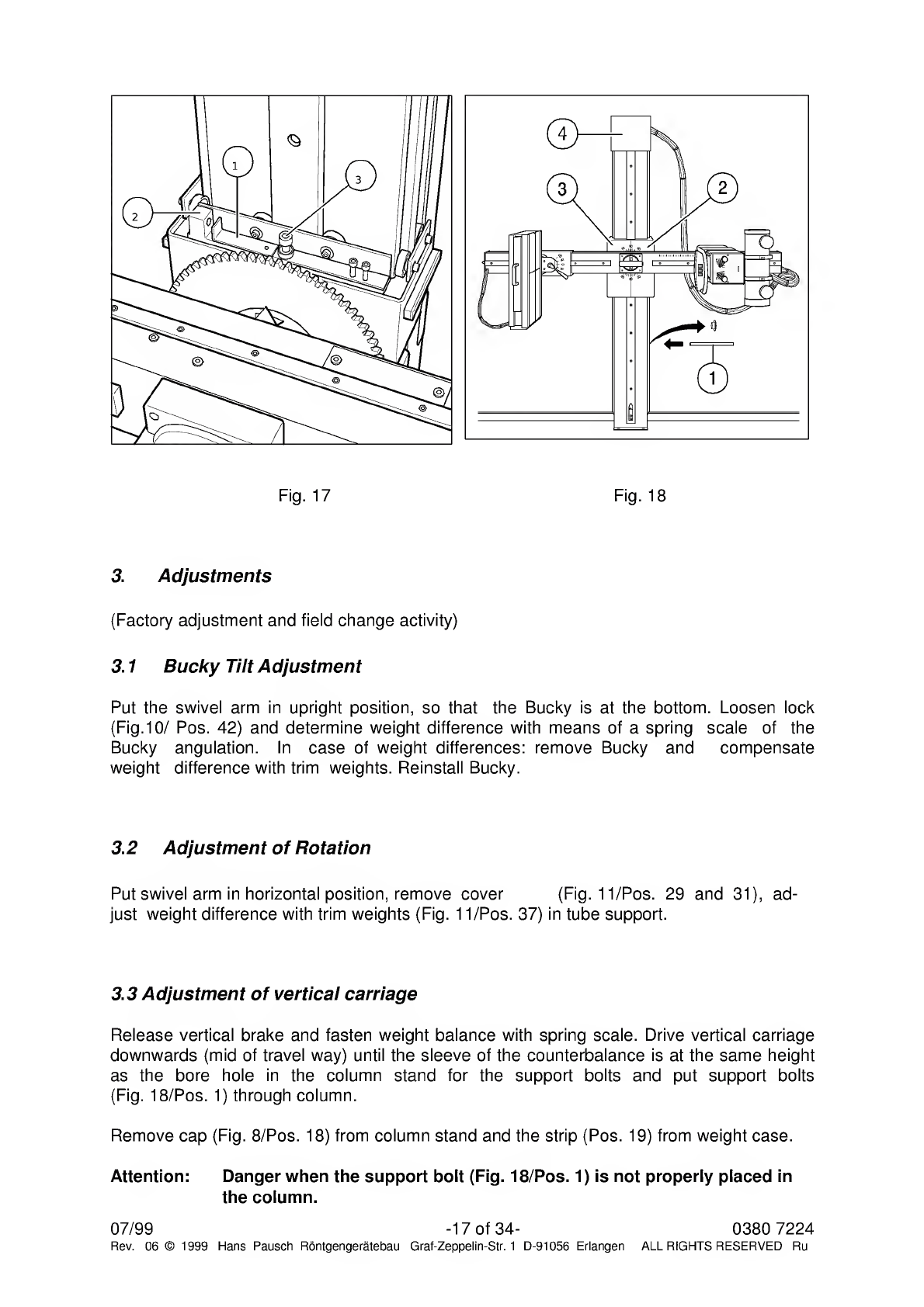
3.
Adjustments
(Factory
adjustment
and
field
change
activity)
3.1
B
ucky
Tilt
Adjustment
Put
the
swivel
arm
in
upright
position,
so
that
the
Bucky
is
at
the
bottom.
Loosen
lock
(Fig.10/
Pos.
42)
and
determine
weight
difference
with
means
of
a
spring
scale
of
the
Bucky
angulation.
In
case
of
weight
differences:
remove
Bucky
and
compensate
weight
difference
with
trim
weights.
Reinstall
Bucky.
3.2
A
djustment
of
Rotation
Put
swivel
arm
in
horizontal
position,
remove
cover
(Fig.
11/Pos.
29
and
31),
ad¬
just
weight
difference
with
trim
weights
(Fig.
11/Pos.
37)
in
tube
support.
3.3
A
d
justment
of
vertical
carriage
Release
vertical
brake
and
fasten
weight
balance
with
spring
scale.
Drive
vertical
carriage
downwards
(mid
of
travel
way)
until
the
sleeve
of
the
counterbalance
is
at
the
same
height
as
the
bore
hole
in
the
column
stand
for
the
support
bolts
and
put
support
bolts
(Fig.
18/Pos.
1)
through
column.
Remove
cap
(Fig.
8/Pos.
18)
from
column
stand
and
the
strip
(Pos.
19)
from
weight
case.
Attention:
Danger
when
the
support
bolt
(Fig.
18/Pos.
1)
is
not
properly
placed
in
the
column.
07/99
-17
of
34-
0380
7224
Rev.
06
©
1999
Hans
Pausch
Rontgengeratebau
Graf-Zeppelin-Str.
1
D-91056
Erlangen
ALL
RIGHTS
RESERVED
Ru
Switch
off
power
supply.
Adjust
weight
difference
with
weight
plates
and
insert
in
counter¬
weight
box.
Install
security
sleeve
(Fig.
8/Pos.
19)
onto
counterweight
box
and
lock
column
with
cap
(Pos.
18).
Remove
support
bolt
(Fig.
18/Pos.
1)
from
column.
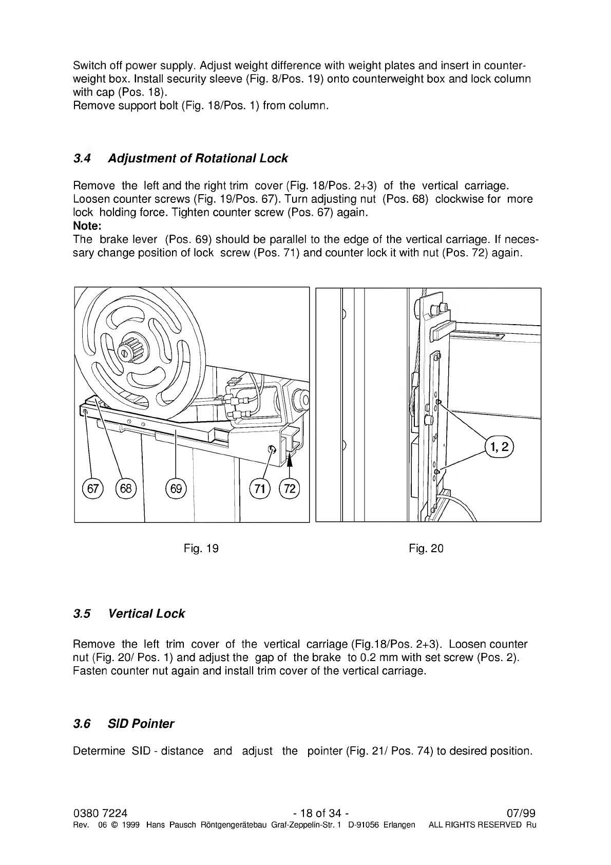
3.4
A
djustment
of
Rotational
Lock
Remove
the
left
and
the
right
trim
cover
(Fig.
18/Pos.
2+3)
of
the
vertical
carriage.
Loosen
counter
screws
(Fig.
19/Pos.
67).
Turn
adjusting
nut
(Pos.
68)
clockwise
for
more
lock
holding
force.
Tighten
counter
screw
(Pos.
67)
again.
Note:
The
brake
lever
(Pos.
69)
should
be
parallel
to
the
edge
of
the
vertical
carriage.
If
neces¬
sary
change
position
of
lock
screw
(Pos.
71)
and
counter
lock
it
with
nut
(Pos.
72)
again.
)
(
1
rp
i#
0
(I
0
\
=
o
)
/
0
0
(.•>)
0/[
ir\_
3.5
V
ertical
Lock
Remove
the
left
trim
cover
of
the
vertical
carriage
(Fig.18/Pos.
2+3).
Loosen
counter
nut
(Fig.
20/
Pos.
1)
and
adjust
the
gap
of
the
brake
to
0.2
mm
with
set
screw
(Pos.
2).
Fasten
counter
nut
again
and
install
trim
cover
of
the
vertical
carriage.
3.6
S
ID
Pointer
Determine
SID
-
distance
and
adjust
the
pointer
(Fig.
21/Pos.
74)
to
desired
position.
0380
7224
-
18
of
34
-
07/99
Rev.
06
©
1999
Hans
Pausch
Rontgengeratebau
Graf-Zeppelin-Str.
1
D-91056
Erlangen
ALL
RIGHTS
RESERVED
Ru

3.7
SID
Drive
Clutch
Remove
cover
(Fig.22/Pos.
76).
Adjust
the
torque
with
means
of
the
3
screws
(Pos.
77).
For
higher
torque
turn
screws
(Pos.
77)
clockwise.
Note:
The
stop
motion
force
of
the
Bucky-
or
tube
carriage
should
be
set
to
150
N
max.
Secure
screws
with
locking
dye
and
mount
cover
again.
Fig.
21
Fig.
22
3.8
SID
End
Switch
Remove
end
cover
of
swivel
arm
(Fig.23/Pos.
79).
Drive
SID
to
minimum
distance
possi¬
ble.
Loosen
trip
cam
(Pos.
81)
with
socket
wrench
and
turn
the
cam
until
switch
(Pos.
82)
is
actuated.
Tighten
trip
cam.
Put
SID
to
maximum
distance,
loosen
trip
cam
(Pos.
83)
and
turn
it
until
switch
(Pos.
84)
is
actuated.
Fasten
trip
cam
again.
Note:
The
SID
is
variable
from
1
m
to
2
m
distance
but
can
be
limited
in
any
intermediat
distance.
Install
trim
cover
(Pos.
79)
again.
07/99
-19
of
34-
0380
7224
Rev.
06
©
1999
Hans
Pausch
Rontgengeratebau
Graf-Zeppelin-Str.
1
D-91056
Erlangen
ALL
RIGHTS
RESERVED
Ru
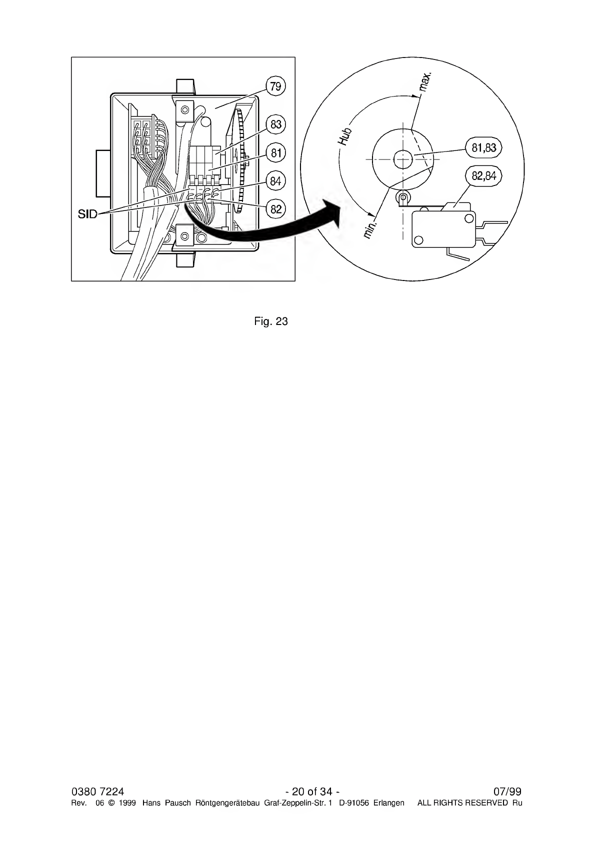
Fig.
23
0380
7224
-
20
of
34
-
07/99
Rev.
06
©
1999
Hans
Pausch
Rontgengeratebau
Graf-Zeppelin-Str.
1
D-91056
Erlangen
ALL
RIGHTS
RESERVED
Ru
Table of contents
Other Hans Pausch Industrial Equipment manuals


