Hans Pausch CS 2000 User manual

Mounting
Instructions
CS2
•Ml
English
Edition
08/98
-lot
44-
0125
7221
Revision
02
©1998
Hans
Pausch
Rontgengeratebau
Graf-Zeppelin-Str.
1
D-91056
Erlangen
ALL
RIGHTS
RESERVED
Ru

TABLE
OF
CONTENTS
1.
Specification
1.1
General
safety
notes
1.2
Compatibility
1.3
Climatic
conditions
1.4
Dimensions
and
weights
1.5
Component
Designation
1.6
Dimensional
Drawings
1.7
Dimensional
Drawings/Floor
Mounting
1.8
Installation
of
high
tension
cables
1.9
Constructional
preparations
1.10
Necessary
measuring
means
1.11
Necessary
special
tools
1.12
Power
supply
data
1.13
Schematics
1.14
Component
Numbers
and
Designation
2.
Mounting
of
Unit
2.1
Unpack
equipment
parts
2.2
Assembly
of
the
table
and
rail
stand
2.3
Assembly
of
the
column
2.4
Assembly
of
Bucky
2.5
Assembly
of
the
table
plate
2.5.1
Assembly
of
the
table
plate
2.6
Assembly
of
the
tube
and
collimator
2.7
Assembly
of
the
tube
holding
support
2.8
Assembly
of
the
tube
on
tube
holding
support
2.9
Assembly
of
the
control
arm
2.10
Assembly
and
installation
of
the
cable
2.11
Counterweight
on
the
column
2.12
Function
control
2.13
Assembly
of
covers
3.
Adjustments
3.1
Adjustment
of
the
column
vertical
3.2
Adjustment
of
the
column
in
direction
of
rotation
3.3
Adjustment
of
the
rotational
axis
respectively
the
supporting
arm
3.4
Adjustment
of
the
rotation
detent
(0°,
90
°)
3.5
Adjustment
of
the
Bucky
in
table
transverse
direction
3.6
Adjustment
of
the
vertical
FFA
switch
4.0
Technical
Maintenance
4.1
Mechanical
and
electrical
tests
4.2
Spare
Parts
Table
4.2.1
Spare
Parts
Column
4.3
Spare
Parts
List
4.4
Maintenance
Documentation
4.5
Name
Plate
Location
0125
7221
-
2
Of
44-
Revision
02©
1998
Hans
Pausch
Rontgengeratebau
Graf-Zeppelin-Str.
1
D-91056
Erlangen
Sheet
3
3
3
3
4
5
6
7
7
7
7
7
8
14
16
17
18
19
20
21
21
23
23
24
25
25
26
26
28
28
29
29
29
30
31
37
38
40
43
44
08/98
ALL
RIGHTS
RESERVED
Ru

1.
Technical
data
1.1
G
eneral
safety
notes
In
the
Federal
Republic
of
Germany,
the
electrical
installation
of
rooms
for
medical
purposes
must
conform
to
the
provisions
VDE
Standard
0107.
In
all
other
countries
the
national
requirements
have
to
be
observed.
Check
the
installation
layout
plan.
During
the
installation
it
is
important
to
check
that
all
protective
ground
wire
connections
provided
by
the
manufacturer
are
properly
made
before
the
equipment
is
started
up.
The
protective
ground
wires
between
the
individual
system
components
and
the
power
supply
have
to
be
connected
as
shown
in
the
wiring
diagram.
Regulation
of
professional
associations
concerning
safety
and
accident
prevention
has
to
be
observed.
No
work
may
be
performed
on
parts
carrying
a
voltage
higher
than
42
V.
If
it
is
necessary
to
turn
on
the
power
for
execution
of
movements
of
the
equipment
in
the
course
of
installation
procedure,
it
must
be
shut
down
immediately
after
completion
of
these
movements.
1.2
C
ompatibility
This
mounting
instruction
is
valid
for
CS
2000
and
all
versions
of
them.
The
table
carries
all
customary
in
trade
Bucky
units.
A
Bucky
Wall
stand
can
be
installed
on
the
right
or
left
side
of
the
table
depending
on
the
user
side.
1.3
C
limatic
conditions
During
regular
work:
Temperature:
10°Cto40°C
Humidity:
20%
to
80%
Air
pressure:
700
hPA
to
1100
hPa
During
transport:
Temperature:
-25°Cto70°C
Humidity:
5%
to
95%
Air
pressure:
600
hPA
to
100
h
PA
1.4
D
imensions
and
weights
of
components
Dimensions
of
components
Weights
Table
1400x770x750
mm
120
kg
Tabletop
2200x810x
40
mm
35
kg
Column
2320x470x302
mm
155
kg
Rail
stand
2250x183x302
mm
80
kg
Tube
stand
with
vertical
carriage
600x500x200
mm
22
kg
of
collies
Dimensions
of
collies
Weights
Table
1530x860x960
mm
155
kg
Tabletop
2320x930x200
mm
56
kg
Column
Rail
stand
2400x780x760
mm
330
kg
Tube
stand
with
vertical
carriage
08/98
-
3
of
44-
0125
7221
Revision
02
©1998
Hans
Pausch
Rontgengeratebau
Graf-Zeppelin-Str.
1
D-91056
Erlangen
ALL
RIGHTS
RESERVED
Ru

1.5
Component
Designation
A
Table
top,
floating,
manually
movable,
scratch-proof
B
Profile
rail
with
trim
cover,
smooth,
accepts
accessories
C
Upper
table
frame
D
Bucky
unit,
movable
E
Table
base,
solid,
vibration-free
F
Guide
rails
for
tube
stand
G
Foot
treadle
H
Vertical
carriage
with
X-ray
tube
support
arm
I
Tube
stand,
rotatable
K
X-ray
tube
L
Control
arm
M
Protractor
0125
7221
-4
of
44-
08/98
Revision
02©
1998
Hans
Pausch
Rontgengeratebau
Graf-Zeppelin-Str.
1
D-91056
Erlangen
ALL
RIGHTS
RESERVED
Ru

1.6
Dimensional
Drawings
08/98
-
5
of
44-
0125
7221
Revision
02
©1998
Hans
Pausch
Rontgengeratebau
Graf-Zeppelin-Str.
1
D-91056
Erlangen
ALL
RIGHTS
RESERVED
Ru

1.7
Dimensional
Drawings/Floor
Mounting
/'
/
/
/
/
/
/
/
/
/
/
/
/
/
/
/
/
/
/
/
/
/
/
/
/
/
/
min.
930
///,//////
*
o
c
'E
460
o
CNI
O
CNI
400
**
540
*
o
o
o
50
O
lo
|CTN
CNI
CNI
NO
CNI
CNI
NO
X
460
o
NO
ON
o
o
CNI
Ansicht
X
satlicher
Kabeleinlafl
o
o
CNI
o
NO
ON
/
/
/
/
/
o
Befestigungspunkte
/
floor
mounting
holes
(
)
bei
Aufstellung
fur
Wandstativ
rechts
(wahlweise)
mounting
for
WBS
right
hand
(optional)
*
ohne
Wandstativ
(Mindestabstande
nach
DIN
31001)
without
WBS
(min.
distances
according
to
DIN
31001)
#*
moglicher
Kabelaustritt
am
FuHboden
cable
outlet
area
on
the
floor
0125
7221
-
6
of
44-
08/98
Revision
02©
1998
Hans
Pausch
Rontgengeratebau
Graf-Zeppelin-Str.
1
D-91056
Erlangen
ALL
RIGHTS
RESERVED
Ru

1.8
Installation
of
high
tension
cables
1.9
Constructional
preparations
The
electrical
connection
data
have
to
correspond
with
the
of
the
equipment
supply
voltage.
For
the
CS
2000
is
only
a
supply
voltage
of
115/230
V
required
and
a
corresponding
ground
connection
transmission.
The
mounting
points
of
the
CS
2000
have
to
support
a
tractive
power
of
2500
N
at
each
mounting
point
(concrete
floor?
B
150
DIN
1045
when
using
the
included
fastening
material).
Prepare
on
the
floor
fastening
bore-holes
of
12
mm
according
to
drawing
1.6.,
under
consideration
of
the
construction.
The
connection
cable
of
the
CS
2000,
the
Bucky
and
the
detector
has
to
be
placed
constructional
depending
on
the
version
until
the
terminal
box
in
the
table
base
or
until
the
Bucky
according
to
the
installation
plan.
The
optional
ceiling-
wall-
terminal
box
can
be
mounted
if
required
to
the
wall
or
ceiling.
1.10
Necessary
measuring
means
Machine
air
level
1.11
Necessary
special
tools
Percussion
bore
machine
Rock
drill
12
mm
Socket
head
cap
key
6
mm
and
4
mm
shortened
(is
included)
1.12
Power
supply
data
Power
supply:
115/230
V
Frequency:
50
/
60
Hz
Rated
current:
2/1
A
Rated
power
supply
voltage:
220
VA
08/98
-
7
of
44-
0125
7221
Revision
02
©1998
Hans
Pausch
Rontgengeratebau
Graf-Zeppelin-Str.
1
D-91056
Erlangen
ALL
RIGHTS
RESERVED
Ru

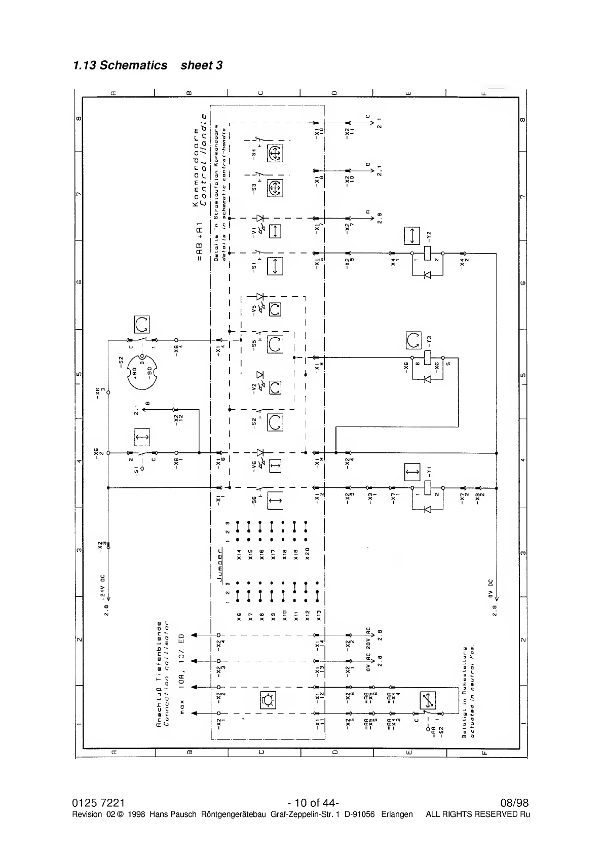
1.13
Schematics
sheet
1
1.13.1
Description
at
Schematics
.
S
chematics
sheet
2
=
AX
control
panel
=
Unit,
Indication
.
S
chematics
sheet
3
=
AX
control
panel
=
Unit,
Indication
1.13.1
Table
of
contents
at
Schematics
Sheet
2
Schematics
=AA
Sheet
3
Schematics
=AB
Sheet
4
Schematics
=AB
Sheet
5
Wiring
diagram
=AA
Sheet
6
Wiring
diagram
=AB
0125
7221
-
8
of
44-
08/98
Revision
02©
1998
Hans
Pausch
Rontgengeratebau
Graf-Zeppelin-Str.
1
D-91056
Erlangen
ALL
RIGHTS
RESERVED
Ru

08/98
-
9
of
44-
0125
7221
Revision
02
©1998
Hans
Pausch
Rontgengeratebau
Graf-Zeppelin-Str.
1
D-91056
Erlangen
ALL
RIGHTS
RESERVED
Ru
0125
7221
-
10
of
44-
08/98
Revision
02©
1998
Hans
Pausch
Rontgengeratebau
Graf-Zeppelin-Str.
1
D-91056
Erlangen
ALL
RIGHTS
RESERVED
Ru

1.13
Schematics
sheet
4
08/98
-
11
of
44-
0125
7221
Revision
02
©1998
Hans
Pausch
Rontgengeratebau
Graf-Zeppelin-Str.
1
D-91056
Erlangen
ALL
RIGHTS
RESERVED
Ru
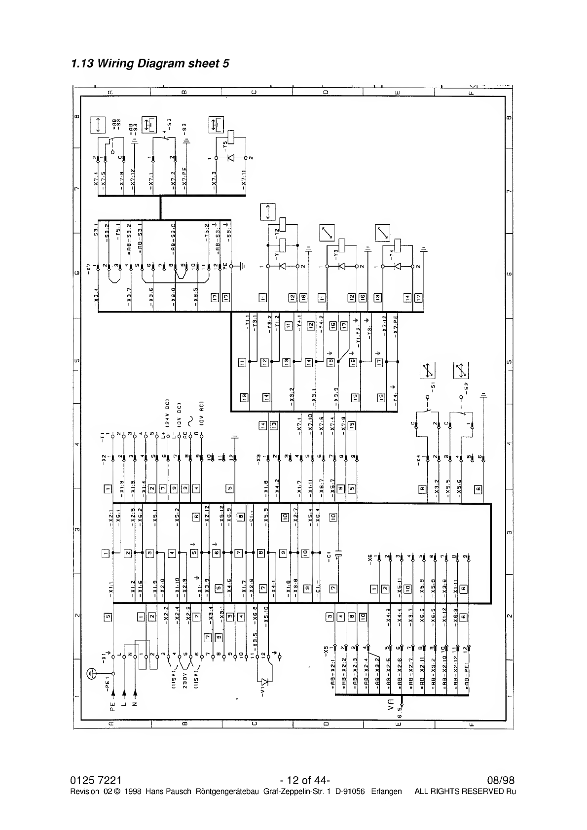
1.13
Wiring
Diagram
sheet
5
0125
7221
-
12
Of
44-
Revision
02©
1998
Hans
Pausch
Rontgengeratebau
Graf-Zeppelin-Str.
1
D-91056
Erlangen
08/98
ALL
RIGHTS
RESERVED
Ru

1.13
Wiring
Diagram
sheet
6
08/98
-
13
of
44-
0125
7221
Revision
02
©1998
Hans
Pausch
Rontgengeratebau
Graf-Zeppelin-Str.
1
D-91056
Erlangen
ALL
RIGHTS
RESERVED
Ru
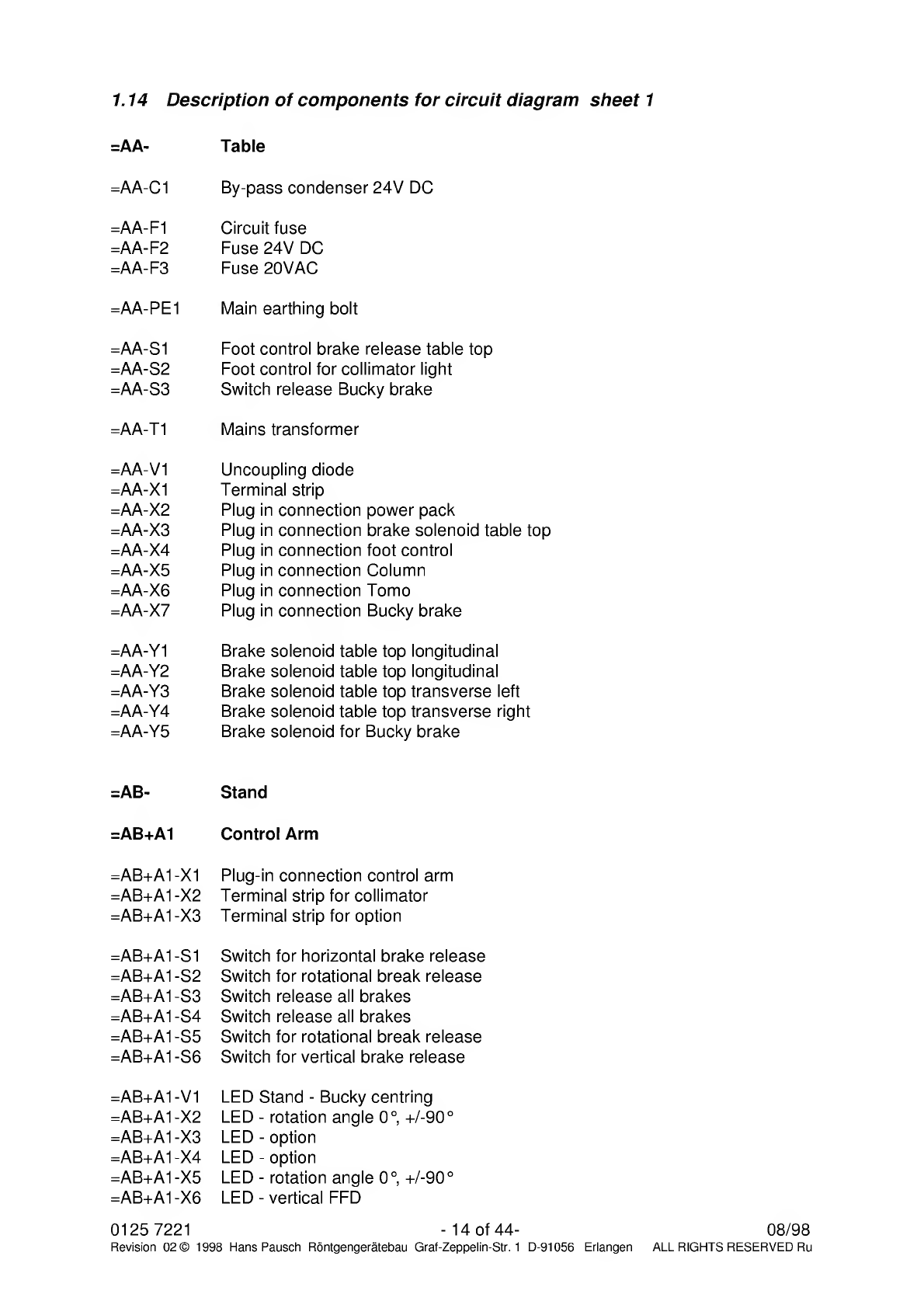
1.14
Description
of
components
for
circuit
diagram
sheet
1
=AA-
Table
=AA-C1
By-pass
condenser
24V
DC
=AA-F1
Circuit
fuse
=AA-F2
Fuse
24V
DC
=AA-F3
Fuse
20VAC
=AA-PE1
Main
earthing
bolt
=AA-S1
Foot
control
brake
release
table
top
=AA-S2
Foot
control
for
collimator
light
=AA-S3
Switch
release
Bucky
brake
=AA-T1
Mains
transformer
=AA-V1
Uncoupling
diode
=AA-X1
Terminal
strip
=AA-X2
Plug
in
connection
power
pack
=AA-X3
Plug
in
connection
brake
solenoid
table
top
=AA-X4
Plug
in
connection
foot
control
=AA-X5
Plug
in
connection
Column
=AA-X6
Plug
in
connection
Tomo
=AA-X7
Plug
in
connection
Bucky
brake
=AA-Y1
Brake
solenoid
table
top
longitudinal
=AA-Y2
Brake
solenoid
table
top
longitudinal
=AA-Y3
Brake
solenoid
table
top
transverse
left
=AA-Y4
Brake
solenoid
table
top
transverse
right
=AA-Y5
Brake
solenoid
for
Bucky
brake
=AB-
Stand
=AB+A1
Control
Arm
=AB+A1-X1
Plug-in
connection
control
arm
=AB+A1
-X2
Terminal
strip
for
collimator
=AB+A1
-X3
Terminal
strip
for
option
=AB+A1-S1
Switch
for
horizontal
brake
release
=AB+A1
-S2
Switch
for
rotational
break
release
=AB+A1-S3
Switch
release
all
brakes
=AB+A1-S4
Switch
release
all
brakes
=AB+A1
-S5
Switch
for
rotational
break
release
=AB+A1-S6
Switch
for
vertical
brake
release
=AB+A1-V1
LED
Stand
-
Bucky
centring
=AB+A1-X2
LED
-
rotation
angle
0°,
+/-90
0
=AB+A1-X3
LED
-
option
=AB+A1-X4
LED
-
option
=AB+A1-X5
LED
-
rotation
angle
0°,
+/-90
0
=AB+A1-X6
LED
-
vertical
FFD
0125
7221
-
14
of
44-
08/98
Revision
02©
1998
Hans
Pausch
Rontgengeratebau
Graf-Zeppelin-Str.
1
D-91056
Erlangen
ALL
RIGHTS
RESERVED
Ru

1.14
Description
of
components
for
circuit
diagram
sheet
2
=AB-K1
Relay
for
optional
FFD
=AB-PE
Main
earthing
bolt
Stand
=AB-S1
FFD
switch
vertical
=AB-S2
Switch
tube
rotation
0°,
+/-90
0
=AB-S3
Switch
Bucky
engaged
=AB-S4
FFD
switch
horizontal
40“
=AB-S5
FFD
switch
horizontal
72“
=AB-X2
Plug-in
connection
for
tube
support
arm
=AB-X3
Plug-in
connection
for
vertical
brake
=AB-X4
Plug-in
connection
for
horizontal
brake
=AB-X5
Plug-in
connection
for
collimator
=AB-X6
Terminal
strip
in
the
tube
support
arm
=AB-X7
Plug-in
connection
in
vertical
brake
=AB-X9
Plug-in
connection
for
=AC-S3
=AB-X10
Plug-in
connection
for
=AB-S4,
-S5
=AB-Y1
Vertical
brake
=AB-Y2
Horizontal
brake
=AB
08/98
-
15
of
44-
0125
7221
Revision
02
©1998
Hans
Pausch
Rontgengeratebau
Graf-Zeppelin-Str.
1
D-91056
Erlangen
ALL
RIGHTS
RESERVED
Ru

2.
Mounting
2.1
Unpack
equipment
parts
Remove
table
from
the
palette
In
addition:
Remove
both
artificial
caps
(Fig.
1
Pos.
1)
and
loosen
beneath
the
socket
head
cap
screw.
Tilt
front
plate
„above“
(Pos.
2)
carefully
to
the
outside
and
then
take
out
from
underneath.
Take
out
accessory
box
from
the
table.
Fig.
1
Fig.
2
Dismount
the
below
placed
table
cover
(Fig.
2/Pos.
3)
with
both
screws
(Pos.4).
Loosen
both
transport
screws
(Fig.2/Pos.
5)
from
the
palette
and
push
to
the
bottom.
Push
the
table
to
the
back
from
the
palette
(Fig.
3).
Tilt
table
to
the
back,
pull
out
palette
to
the
front
and
take
off
the
table
carefully.
Fig.
3
Fig.
4
0125
7221
-
16
of
44-
08/98
Revision
02©
1998
Hans
Pausch
Rontgengeratebau
Graf-Zeppelin-Str.
1
D-91056
Erlangen
ALL
RIGHTS
RESERVED
Ru

Dismount
both
closing
caps
(Fig.
4/Pos.
7
and
8)
and
loosen
the
transport
security
screws
of
the
rail
stand,
then
push
to
the
bottom.
Remove
rail
stand
from
the
palette
and
take
to
the
assembly
area.
Dismount
transport
security
plates
of
the
column.
(Leave
column
on
the
palette
until
assembly).
Unpack
equipment
parts
and
check
for
completeness
according
to
shipping
list
respectively
order.
Check
complete
delivery
upon
damage
before
assembly
start.
2.2
Assembly
of
the
table
and
rail
stand
Take
the
table
to
assembly
area.
Place
the
rail
stand
behind
the
table.
Align
the
rail
stand
(Fig.
5/Pos.9)
to
the
right
or
left
side
of
the
table
(Pos.
10)
depending
on
the
way
of
assembly
(according
to
drawing
for
installation
of
a
Bucky
wall
stand
left
or
right).
Fig.
5
Fig.
6
Fasten
the
rail
stand
with
4
screws
(Pos.
11)
to
the
table.
Push
table
with
rail
stand
over
the
fastening
bore-holes
at
the
assembly
place.
Respectively
align
the
table
at
the
assembly
place,
mark
the
5
fastening
bore-holes
and
bore.
Insert
the
included
set
pin
(Fig.
6)
and
insert
screws
and
washers.
Fig.
7
Fig.
8
08/98
-
17
of
44-
0125
7221
Revision
02
©1998
Hans
Pausch
Rontgengeratebau
Graf-Zeppelin-Str.
1
D-91056
Erlangen
ALL
RIGHTS
RESERVED
Ru

Align
table
with
rail
stand
according
to
air
level
(Fig.
7
Pos.
1,2
and
Fig.
8/Pos.
3).
If
necessary,
align
with
washers
(Fig.
9/Pos.
4
and
5).
Fasten
all
screws
tightly.
Fig.
9
Fig.
10
2.3
Assembly
of
the
column
The
column
will
be
shipped
with
inserted
counterweights.
The
counterweight
in
the
column
is
secured
for
the
transport
with
two
screws.
Attention:
Remove
transport
security
not
before
assembly
of
the
tube
and
collimator.
To
insert
the
column
into
the
rail
stand
easily,
an
assembly
plate
is
included
to
the
shipment.
It
is
constructed
so
that
it
can
slide
on
a
normal
floor
easily.
Dismount
limit
stop
(Fig.
10
Pos.
1)
from
the
rail
stand.
Set
up
(Fig.
11/Pos.
1)
and
place
on
the
assembly
plate
(Pos.
2).
Push
the
assembly
plate
to
the
rail
stand
and
align
(Fig.
11/Pos.
2).
Insert
the
column
from
the
assembly
plate
into
the
rail
stand.
Remark:
When
inserting
pay
attention
the
bearing
and
brake
magnet.
Mount
the
limit
stop
(Fig.
10/Pos.
1)
again
to
the
rail
stand.
0125
7221
-
18
of
44-
08/98
Revision
02©
1998
Hans
Pausch
Rontgengeratebau
Graf-Zeppelin-Str.
1
D-91056
Erlangen
ALL
RIGHTS
RESERVED
Ru

Fig.
11
Fig.
12
Mount
the
cable
guide
chain
(Fig.
12/Pos.
1)
to
the
rail
stand
-
back
wall
-
and
to
the
column
carriage
(Pos.
2).
Insert
the
end
of
the
cable
(Pos.
3)
into
the
table.
Mount
the
distributing
plate
(Pos.
4)
to
the
column
carriage.
Dismount
cover
(Fig.
13/Pos.
1)
from
the
catch
(Pos.
2).
Loosen
both
screws
(Pos.
3)
and
mount
the
catch.
Attention:
The
catch
has
to
be
adjusted
in
height
direction
so
that
the
switch
nose
(Pos.
4)
is
centred
to
the
switch
spring
of
the
column
Bucky
coupling.
Fig.
13
Fig.
14
2.4
Assembly
of
Bucky
Remark:
Buckys
of
different
manufacturers
can
be
installed.
The
equipment
will
be
prepared
according
to
the
order
and
the
necessary
fastening
materials
will
be
included
to
the
shipment.
08/98
-
19
of
44-
0125
7221
Revision
02
©1998
Hans
Pausch
Rontgengeratebau
Graf-Zeppelin-Str.
1
D-91056
Erlangen
ALL
RIGHTS
RESERVED
Ru

Insert
the
Bucky
(opening
of
cassette
to
the
front)
in
the
Bucky
carriage
(Fig.14/Pos.l).
Install
connection
cable
and
detector
cable
according
to
the
instructions
of
the
manufacturer.
Bucky
P
Fastening
with
2
screws
each
(Fig.
14/Pos.
3)
left
and
right
lateral.
Put
at
the
top
the
cover
angle
with
the
longer
side
(Fig.
14/Pos.
4)
to
user-
and
back
side
and
fasten
above
with
3
screws
each
and
U-washer.
Philips
Fastening
with
2
screws
(Fig.
14/Pos.
3)
left
and
right
lateral.
Put
at
the
top
the
cover
angle
with
the
longer
side
(Fig.
14/Pos.
4)
to
user-
and
back
side
and
fasten
above
with
3
screws
each.
Siemens
Fastening
with
2
screws
each
(Fig.
14/Pos.
3)
left
and
right
lateral.
2.5
Assembly
of
the
table
plate
Remark:
If
there
are
less
than
2900
mm
from
the
mid
of
table
to
a
wall
available,
please
mount
the
table
plate
according
to
section
2.5.1.
Remove
table
plate
out
of
packing.
Dismount
on
one
grinding
the
limit
stop
(Fig.
18/Pos.
1)
and
push
the
table
top
(Fig.
15/Pos.
2)
on
the
transverse
carriage.
Fig.
15
Fig.
16
Attention:
Pay
attention
to
the
brake
magnets
while
inserting
the
table
top.
Remount
limit
stops
(Fig.
18/Pos.
1)
0125
7221
-
20
of
44-
08/98
Revision
02©
1998
Hans
Pausch
Rontgengeratebau
Graf-Zeppelin-Str.
1
D-91056
Erlangen
ALL
RIGHTS
RESERVED
Ru
Table of contents
Other Hans Pausch Industrial Equipment manuals


Popular Industrial Equipment manuals by other brands

Fiessler
Fiessler AKAS-3PM operating instructions

Siemens
Siemens 3VL91125GB30 operating instructions

Julabo
Julabo SW22 operating manual

Baltimore Aircoil Company
Baltimore Aircoil Company BCP3D Installation, Operating, Maintenance

Siemens
Siemens Sicharge Uc 8EM4 Series Preventive maintenance

Richelieu
Richelieu MAKSIWA Portable EdgeBander instruction manual

Kval
Kval EFX quick start

Siemens
Siemens RUGGEDCOM WIN7035 installation guide

SAMES KREMLIN
SAMES KREMLIN Inocart VT user manual

RK Rose+Krieger
RK Rose+Krieger COPAS-RC Assembly instructions

SCHUNK
SCHUNK ERT 12 Translation of original operating manual

Woodward
Woodward VariStroke-DX Installation and operation manual


