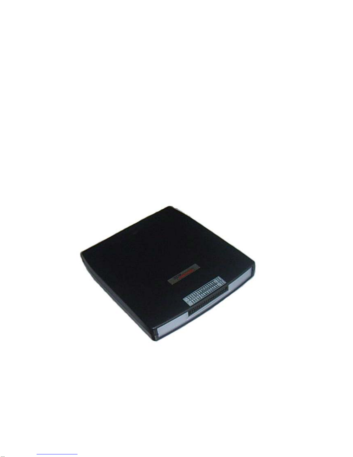
Hantek LA5034 User manual

User’s Guide
LA5034
Operation Manual

Content
General safety summary...................................................................................I
Introduction......................................................................................................II
Chapter 1 Getting started.................................................................................1
System Requirements .......................................................................2
Installing Hardware............................................................................3
Installing Software .............................................................................6
User Interface..................................................................................10
Chapter 2 Menu.............................................................................................11
File...................................................................................................12
View.................................................................................................13
Setup...............................................................................................14
Analyzer...........................................................................................15
Help.................................................................................................16
Chapter 3 Advanced ......................................................................................17
Clock Panel .....................................................................................18
Bus Panel........................................................................................19
Waveform Panel ..............................................................................22
Measurement Panel.........................................................................24
Export Data......................................................................................25
Chapter 4 Trigger...........................................................................................26
Base Trigger Setup..........................................................................27
Advance Trigger Setup....................................................................29
Chapter 5 Plug Manager................................................................................30
Summary.........................................................................................31
Example...........................................................................................32
Appendix........................................................................................................35
Hardware Specification....................................................................36
Channels .........................................................................................37
Block Diagram .................................................................................39
Cleaning and maintenance..............................................................40

LA5034
General safety summary
Understand the following safety precautions to avoid injuries and to prevent
damage to the product or the product of any product link. To avoid possible
dangers, be sure to use the product in accordance with the regulations.
Only qualified personnel to perform maintenance procedures.
Prevent fire and personal injury.
Use the right power cord. Only the country in which the authorized use of
this product for the power line.
Correctly inserted. Probe or test voltage wire connected to the source,
please do not plug.
Products will be grounded. This product through the power of the
grounding wire grounding. To avoid electric shocks, grounding conductor
must be connected to. In this connection the import or export of products
before the end, be sure to correct grounding for this product.
Properly connected probe. Probe the ground with the same potential. Do
not connect high-voltage ground.
See all the terminals rating. To avoid excessive current fire and the
impact, see the product of all the ratings and tags; please connect
products in the product manual inspection prior to understand the detailed
ratings information.
Do not run the product if you open the cover or panel.
Avoid the exposed circuit. Do not connect power after contact with the
exposed joints and components.
Suspected products to failure do not operate. If you suspect that this
product has been a failure, can be qualified maintenance personnel to be
checked.
Maintain proper ventilation.
Do not operate in the humid environment.
Do not flammable and explosive environment operation.
Please keep the product clean and dry surface.
LA5034 USB User’s Manual I

LA5034
LA5034 USB User’s Manual II
Introduction
The LA5034 is a sophisticated 500MHz, 34-channel logic analyzer used for
testing, analysis, and troubleshooting of digital circuits. The LA5034 is
equipped with features found only in more expensive bench type instruments
The use of advanced large-scale integrated circuits, integrated USB 2.0, CPLD,
FPGA, high-frequency digital circuitry, embedded systems, and other
advanced technology, make the LA5034 to be portable, and easy-to-use,
making the LA5034 your best choice in pc-based logic analyzers The
LA5034 is very suitable for electronic measurement engineers, college
students in scientific research and development and teaching assistants.
The User’s Manual describes in detail the operation of the LA5034 as well as
installation of the software.
The LA5034 has a sufficient number of input channels and is capable of
simultaneously observing a lot of information or data flow direction control
information, and in some way of capturing narrow pulse interference.
The LA5034 has the feature of delayed ability to capture the required
observation points around the waveform, in a variety of digital information
capture function.
The LA5034 has adequate memory capacity to be both display error
messages and to find faults in the source state.
The LA5034 has intuitive and flexible displays to facilitate dynamic analysis,
cantransform the information, and the user can use the binary, decimal,
hexadecimal or ASCII that information to facilitate the repair process and
debug.
The LA5034 can be triggered in a variety of ways, can display a very long data
stream, on the basis of the analysis of that part of the information to make
accurate positioning, and capture appropriate information for software analysis
by using its tracking function trigger operation procedures. For hardware,
trigger function can be detected in the system and that the interference and
Burr.
The LA5034 has reliable Burr detection ability. As competition in digital circuit,
the signal crosstalk, interference and power coupling factors, often mixed with
irregular signal in the burr, which will run from an incorrect circuit. The LA5034
can detect through special burr technology to capture and display.

LA5034
Chapter 1 Getting started
This chapter focuses on the following topics:
System Requirements
Installing hardware
Installing software
Understanding of the user interface
LA5034 User’s Manual 1

LA5034
System Requirements
zMinimum System Requirements
Operating System
Windows NT/2000/XP/Vista
Memory
128MB
Graphic Card
Microsoft DirectX supported
Screen resolution: 1024x768
Color depth: 16bit
zRecommended System Requirements
Operating System
Windows 2000/XP/Vista/Win 7
Memory
256MB
Graphic Card
Microsoft DirectX supported
Screen resolution: 1024x768
Color depth: 16bit
LA5034 User’s Manual 2

LA5034
Installing Hardware
1. Connect the A-Type Plug of USB cable to your PC’s USB port.
2. Connect the B-Type Plug of USB cable to LA5034’s USB port.
3. New hardware is found.
4. New hardware search wizard starts.
LA5034 User’s Manual 3

LA5034
5. New hardware search wizard starts to search
6. New hardware wizard installs software
LA5034 User’s Manual 4

LA5034
7. Finish new hardware search wizard.
Caution:
Do not disconnect any device from the USB bus while the computer is
communicating with the LA5034, or you may lose data and/or your ability to
communicate with the LA5034.
If the LED is illuminated but the turns off, the computer has lost
communication with the LA5034.To restore communication, disconnect the
USB cable from the computer, and then reconnect is. This should restore
communication, and the LED should turn back on.
LA5034 User’s Manual 5

LA5034
Installing Software
1. While in Windows, insert the installation CD into the CD-ROM drive.
2. The installation should start up automatically. Otherwise in Windows
Explorer, switch to the CD-ROM drive and run "Setup.exe".
3. The LA5034 Installation is started. Click 'Next' to continue.
LA5034 User’s Manual 6

LA5034
4. Choose a destination directory. Click 'Next' to continue.
5. Check the setup information. Click Next to start copying of files.
LA5034 User’s Manual 7

LA5034
6. This Status dialog is displayed during copying of files.
7. Updating Your System Configuration.
LA5034 User’s Manual 8

LA5034
8. The installation is complete.
LA5034 User’s Manual 9

LA5034
User Interface
LA5034 provide users a simple and full-featured interface so that users do not
have to spend a lot of time to learn.
LA5034 provide clock panel, waveform panel, bus panel, measurement panel,
trigger panel and plug manager.
LA5034 User’s Manual 10

LA5034
Chapter 2 Menu
This chapter focuses on the following topics:
File
View
Setup
Analyzer
Help
LA5034 User’s Manual 11

LA5034
File
zNew Project: Create a new project with default settings
zLoad Project: Open an exist project
zSave Project: Save current project to File
zExport As CSV File: Export data to file as “CSV”
zExport As TXT File: Export data to file as “TXT”
zExport As BMP File: Export data to file as “BMP”
zPrint…: Print the current waveform
zExit: Exit LA5034
LA5034 User’s Manual 12

LA5034
View
zBackground Color: Modify the background color of waveform.
zShow Grid: Show or hide the grid of waveform
zShow Trigger: Show or hide the trigger line of waveform
zShow Mark: Show or hide the mark of waveform
zShow Measurement: Show or hide the measurement of waveform
zZoom In: Enlargement waveform view
zZoom Out: Reduction waveform view
zZoom All: Show entire waveform view
LA5034 User’s Manual 13

LA5034
Setup
zSignal Name Setup: Set the signal name.
zBus Setup: Configure the bus and signals.
zTrigger Setup: Configure the trigger condition.
LA5034 User’s Manual 14

LA5034
Analyzer
zScroll to First Sample: Causes the waveform view to roll to the first
sample position
zScroll to Trigger: Causes the waveform view to roll to trigger
position.
zScroll to Last Sample: Causes the waveform view to roll to the last
sample position
zScroll to Mark: Causes the waveform view to roll to the mark
position
zNew Mark: Create a new Mark
zNew Measurement: Create a new measurement.
zPlug Manager: Configure the plug of LA5034
zAuto set: Set the waveform optimal.
LA5034 User’s Manual 15

LA5034
Help
zHelp Content: Open the User Manual
zAbout: Show the copyright of LA5034
LA5034 User’s Manual 16
Table of contents
Other Hantek Measuring Instrument manuals

Hantek
Hantek CC-650 User manual

Hantek
Hantek DSO3062L User manual

Hantek
Hantek HDG1000A User manual

Hantek
Hantek HT8000 Series User manual

Hantek
Hantek CC-800 User manual

Hantek
Hantek DSO3102 User manual

Hantek
Hantek Hantek2000 Series User manual

Hantek
Hantek HSA2030 User manual

Hantek
Hantek DSO8000 Series User manual

Hantek
Hantek HDG3000C Series User manual