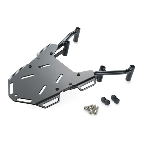
THIS STEP 4 IS SHOWN AS USED WITH A HAPPY
TRAILS SU RACK.
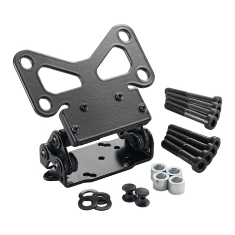
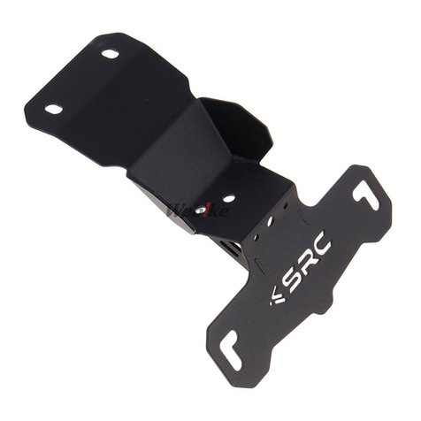
Attach the side plate MT-1 with the angled end to-
ward the rear and angled up. At the rear bolt location,
place the turn signal relocation bracket MT-2 behind
the riser plate with the large end toward the rear and
angled out. Bolt together with an M8x65 SHCS, 2 at
washers, a 3/4”OD x .319”ID x 1/2” L aluminum spacer,
and an M8N lock nut. Position the turn signal bracket
straight back and tighten the mount bolt to 18 /lbs.
At the front mount use an M8x80 SHCS, lock washer,
at washer and a 3/4” x .319” x 3/4” aluminum spacer.
Tighten to 18 /lbs See Fig 4.
Repeat on the other side.
Attach the turn signal to the mounting bracket MT-2 as
shown in Fig 5 using 2 M6x20 SHCS bolts, 4 at wash-
ers and 2 M6N lock nuts.
NOTE: On the le side, the included wire extension will
need to be installed to gain enough wire slack for mount-
ing the turn signal. e right side is longer and will have
enough wire with a little rerouting.
Tighten these bolts to 9 /lbs.
Repeat on the other side.
Fig 5
Step 4
Step 5
THIS STEP 4a IS SHOWN AS USED WITHOUT A
HAPPY TRAILS SU RACK.
Attach side plate MT-1 with the angled end toward the
rear and angled up. At the rear bolt location, place the
turn signal relocation bracket MT-2 behind the side
plate with the large end toward the rear and angled
out. Bolt together with an M8x30 SHCS, 2 at washers
and an M8N lock nut. Position the turn signal bracket
straight back and tighten the mount bolt to 18 /lbs.
At the front bolt location use an M8x35 SHCS, lock
washer and at washer. Tighten to 18 /lbs. See Fig 4a.
Repeat on the other side.
Fig 4
Fig 4aStep 4a
