[2] Notes on safety
ii
A DANGER
/A
Wait at least 5 minutes after turning
off
the power switch a
nd
disco
nn
ecting the power cord from
th
e wall outlet
~
before opening the cover of
th
e control box. Touching areas where high voltages are present can result in severe
injury.
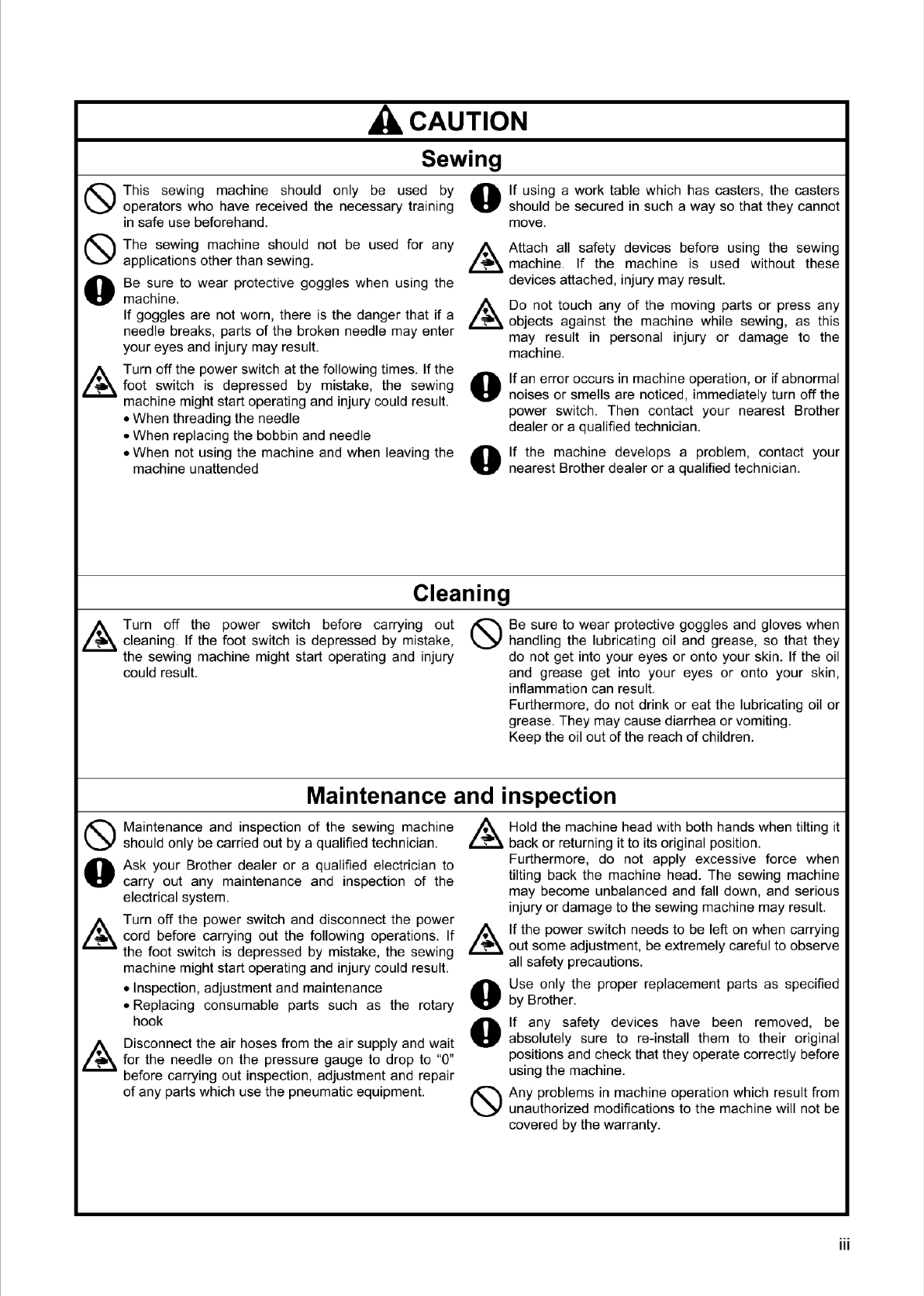
AcAu110N
Environmental requirements
0 Use t
he
sewing machine
in
an area which is free from
sources
of
strong electrical noise such as electrical
line noise
or
staticelectric noise.
Sources
of
strong electrical noise may cause
problems with correct operation.
0 Any fluctuations
in
the power supply voltage should
bewithin ±10%
of
the
ra
te
d voltage for the machine.
Voltage fluctuations which are greater than this may
cause problems with correct operation.
0 The power supply capacity should
be
greaterthan the
requirements for the sewing machine's power
consumption.
Insufficient power supply capacity may cause
prob
le
mswith correct operation.
0 The pneumatic delivery capability should be greater
than the requirements for the sewing machine's total
air consumption.
Insufficient pneumatic delivery capability may cause
problems with correct operation.
0 The ambient temperature should be within the range
of
5°C to 35°C during use.
Temperatures which are lower
or
higher than this
may cause problems with correct operation.
0 The relative humidity should be within the range
of
45% to 85% during use, and no dew formation should
occur in any devices.
Excessively dry
or
humid environments and dew
formation maycause problems with correctoperation.
0 In
th
e event
of
an
electrical sto
rm
, tu
rn
off the power
and disconnect the power cord from the wall outlet.
Lightning may cause problemswith correct operation.
Installation
t<::\
Machine installation should only be ca
rri
ed out by a
\.Y
qualified technician.
0
0
Contact your Brother dealer
or
a qualified electrician
for any electrical work that may need to be done.
The sewing machine weighs approximately 88 kg.
The
in
stallation should be carried out by two
or
mo
re
people.
t<::\
Do not connect the power cord until installation is
\.Y
complete.
If
the foot switch is depressed by mistake,
the sewing machine might start operating and injury
could resul
t.
A Ho
ld
the machine head with both hands when tilting it
~
back or returning itto itsoriginal position.
Furthermore, do not apply excessive force when
tilting back the machine head. The sewing machine
may become unbalanced and fall down, and ser
io
us
injury or damage to the sewing mach
in
e may resul
t.
• Be sure to connect the ground.
If
the ground
connection is not secure, you
ru
n a high risk
of
receiving a serious electric shock, and problems with
correct operation may also occur.
0 All cords should be secured at least 25 mm away
from any moving parts. Furthermore, do not
excessively bend the cords
or
secure them too firmly
t<::\
with staples, otherwise there is the danger that fire
or
\.Y
electric shocks
cou
ld occur.
0
0
Install the safety covers to the machine head and
motor.
If using a work table which has casters,
th
e casters
should be secured
in
such a way so that they cannot
move.
t<::\
Be sure to wear protective goggles and gloves when
\.Y
handling the lubricating
oi
l and
gr
ease, so that they
do not get into your eyes
or
onto your skin.
If
the oil
and grease get into your eyes
or
onto yo
ur
skin,
inflammation can resul
t.
Furthermore, do not drink or eat the lu
br
icating oil
or
grease. They maycause diarrhea or vomiting.
Keep the oil out
of
th
e reach
of
children.
From the library of Superior Sewing Machine & Supply LLC - www.supsew.com