manuals.online logo
Brands
  1. Home
  2. •
  3. Brands
  4. •
  5. Jack
  6. •
  7. Sewing Machine
  8. •
  9. Jack F5 Product guide

Jack F5 Product guide

1 / 8
F5 Control Box Manual Book
SAFETY INSTRUCTION
· Before using this product, please read the product manual and the mechanical manual of the
matching sewing machine.
· This product must be installed or operated by professionally trained personnel.
· Please keep away from arc welding equipment as far as possible to avoid misoperation caused
by electromagnetic wave interference with the controller.
· Please do not use it in places where the room temperature is above 45 °or below 0 °.
· Please do not use in places with humidity below 30% or above 95% or with dew&acid mist.
· When installing the control box and other components, please turn off the power and unplug
the power plug first.
· In order to prevent interference or leakage accidents, please do a good job in grounding
engineering. The grounding wire of the power line must be firmly and effectively connected
with the earth.
· All spare parts for maintenance shall be provided or approved by the company before use.
· Before carrying out any maintenance action, the power supply must be turned off and the
power plug must be unplugged. There is a danger of high voltage in the control box. You must
turn off the power for five minutes before opening the control box.
1. Installation
1.1 Product specification
220V Control box specification
Power voltage AC 220±20% V
Power frequency 50Hz/60Hz
Max output power 550W
110V Control box specification
Power voltage AC 110±20% V
Power frequency 60Hz
Max output power
550W
1.2 Connection of interface plug
Insert the connecting plugs of the pedal and the head into the corresponding socket
behind the control box. The name of each socket is shown in Figure 1-2. After connection,
please check whether the plug is firmly inserted.
○
1
○
2
Figure 1-1 Control box diagram
2 / 8
①Machine head button socket;②Pedal&update socket
Figure 1-2 Definition of control box socket
Note: if it cannot be inserted with normal force, please check whether the plug matches
the socket and whether the insertion direction or pin direction is correct!
1.3 Grounding and wiring
The grounding works of the system must be done well, and shall be constructed by
qualified electrical engineers. Before the product is powered on and put into use, it must be
ensured that the AC input end of the power socket has been safely and reliably grounded. The
grounding wire of the system is yellow green wire, which must be reliably connected to the
safety protection grounding of the power grid to ensure safe use and prevent abnormal
conditions.
Note: all power lines, signal lines, grounding wires and other wiring shall not be
pressed or excessively twisted by other objects to ensure safe use.
2. Display and operation interface
No. Icon Description Explanation
1
Up To quickly set the maximum speed and adjust parameters.
2 Down To reset parameters, enter setting interface, quickly adjust
the maximum speed, etc.
3. Standby interface
In the standby interface, the first digit of the digital tube displays "P", and the
second digit of the digital tube displays the currently set needle stop positions. The
3 / 8
upper and lower needle stop positions are shown in Figure 3-1.
Figure 3-1 upper and lower needle position display interface
4. Quickly speed setting
在In the standby interface, short press the or to set the speed. Short press the
to increase the speed by 100RPM (value increases by 1), short press to decrease
the speed by 100RPM (value decreases by 1), long press ( ) to realize rapid
increase (decrease), the setting parameters are saved automatically.
5. Needle stop positions setting
Long press in the standby interface to set the needle stop positions, and the
parameters will be saved automatically.
6. Parameters setting
Long press and (for around 3S) in the standby interfaceto enter the parameter
setting interface. The first digit nixie tube displays "F" and the second digit nixie tube
does not display (hereinafter referred to as "F interface", which is one of the setting
interfaces), as shown in figure 6-1.
Figure 6-1 F interface
4 / 8
After entering the F interface, press to change the parameter number, press to
show the corresponding parameter value, and then press to change the parameter
value; If the parameter value is modified, press to save, shows "oK" (as shown in
Figure 6-4), and return to the current serial number display interface. If the parameter
value is not modified, directly return to the current serial number display interface. In
the setting interface, the motor operation will exit to the standby interface.
6.1 Speed controller model modification
Taking speed controller model selection as an example, long press and (for
around 3S) in the standby interface to enter the parameter setting F interface (as
shown in Fig. 6-1), and then short press to change the serial number to B to display
the default parameter value 0 (as shown in Fig. 6-2, corresponding to the flat sewing
computer model). If you want to modify the parameters, you can press to change the
parameter value to 1 (as shown in Fig. 6-3, corresponding to ZB simple type), and
then short press to save. After "oK" is displayed, the parameters are modified
successfully. Then return to the standby interface, power off and replace the governor.
When the power on panel shows no error, the governor is replaced. If there is an error,
please check whether the speed controller model matches or not.
Figure 6-2 b0 Figure 6-3 b1
F interface parameters number show as the following sheet
Parameter
number Definition Setting
range
Defaul
t value
Note
L Max sewing speed 05 - 50
40 Increase/decrease by 500rpm
M Needle position switch 0 - 1 1 0:Off 1:On
d Complementary stitch
function switch 0 - 2 1 0:Off 1:Half stitch 2:One stitch
G Safety switch 0 - 1 1 0:Off 1:On
H Dormancy time 0 - 6 3 Unit:10min 0: Off
C Acceleration 0 - 9 5 The higher value, the faster acceleration
n Point stitch 0 - 9 6 The larger value, the larger point stitch
interval
V Speed display enable 0 - 1 0 0:Off 1:On
5 / 8
R Low voltage alarm value
0、10-15
0
220V control box
0:Off 10:100VAC 11:
110VAC
12:120VAC 13:130VAC 14:
140VAC
15:150VAC
110V control box
0:Off 10:50VAC 11:55VAC
12:60VAC 13:65VAC 14:70VAC
15:75VAC
Y High voltage alarm
value 0、26-31
29
220V control box
0:Off 26 :264VAC 27 :
274VAC
28:284VAC 29:294VAC 30:
304VAC
31:314VAC
110V control box
0:Off 26 :132VAC 27 :
137VAC
28:142VAC 29:147VAC 30:
152VAC
31:157VAC
A Ridge crossing
assistance 0 - 1 1 0:Off 1:On
b Speed controller model
selection 0 - 1 0 0:Computerized type 1:ZB simple
type
U Upper position after
start up 0 - 1 1 0:Off 1:On
Figure 6-4 oK
7. Factory reset
Long press for 3S in standby interface, all parameters will be restored to the
factory settings, and the digital tube will display "oK".
8. Description of monitoring mode parameters
Long press for 3S in the F interface to enter the monitoring mode. The first
6 / 8
digital tube displays "J", and the second digital tube does not display (hereinafter
referred to as the monitoring interface). Short press to change parameter number
in the monitoring interface, and press to display the corresponding monitoring
value. Press again in the J5 interface to switch and display the historical fault code.
Short press to return to the current serial number display interface, and short
press in J interface to return to P interface. In J9 interface, press to switch and
display the middle value of current pedal standby position state, and then press to
have further change the parameter value; If the parameter value is modified, press
save to display "oK" and return to the monitoring interface. If the parameter value is
not modified, then it will directly return to the monitoring interface. In addition to J0,
J1 and J2 entering the display interface of pedal voltage, speed and power, the
real-time pedal voltage, power and speed will be displayed during operation. In other
monitoring interfaces, the motor will exit the j interface and return to the P interface.
The parameter number of the monitoring interface show as following sheet:
No. Definition Description
J0 Pedal voltage
monitoring
Display the pedal voltage value in standby and running states, and
the displayed number / 10 = the actual pedal voltage value
J1 Speed Display the real-time speed in standby and running mode, and the
displayed number * 100 = actual speed
J2 Power Display the real-time power in standby and running states, and the
displayed number *10 = actual power
J3 Voltage Display the input voltage in standby mode, and the displayed
number * 10 = actual voltage
J4
Historical
maximum
voltage
Display the highest input voltage in history, and the displayed
number * 10 = actual voltage
J5 Historical error
code
Display historical error codes (dumping error E7 is not recorded,
only the latest 5 are displayed, and 00 is displayed when there is no
error record). Automatically return to the standby interface if no any
further operation within 8S
J6
Cumulative
running time of
control box
Display the cumulative operation time of electric control, and the
displayed number * 100 = actual time (hour)
J7 Aging
monitoring For manufacture test
J8 Model code 1/FF:F5; 2:20U; 3:8558G/8560G
J9
Speed
controller
standby range
adjustment
Display the middle value of voltage under current pedal standby
state, display number/10=actual voltage. Revise the parameter, the
speed controller standby range will change according to the revise
of middle value of voltage timely.
Note: some versions have no J8 monitoring items
9. One key to clear the error
Press to clear the error. When the system reports an error and displays an error
alarm, press to re detect whether the error exists. If it does not exist, the error alarm
will be released, and if it exists, the alarm will continue (this function is only limited
to E4, E5 and shutdown reminder of); When the system reports error E5 (abnormal
locator signal) or E7 (head safety switch alarm), long press to close the needle stop
7 / 8
function or safety switch alarm function and release the alarm; If the alarm is not
released, the alarm number will be displayed until the fault is eliminated. See the error
code description table for the detailed error code sheet.
10. Digital tube display description
Numbers:
Actual
Value 0 1 2 3 4 5 6 7 8 9
Digital tube
content
Letters:
Actual
Letter A B C D E F G H I J
Digital tube
content
Actual
Letter K L M N O P Q R S T
Actual
Letter
Actual
Letter U V W X Y Z
Digital tube
content
11. Error code sheet
Error
code Content Advice
OF
The machine has not
been running for about
30 minutes and enters
the sleep state
The supply voltage is
too low
Press or key to wake up the machine;
If the alarm cannot be eliminated, please check whether the
power supply voltage is normal;
E1 Motor stuck
Please rotate the hand wheel to check whether the machine
head is stuck or dry, and it is difficult to rotate;
Check whether the motor plug-in is loose or falls off;
Check whether the materials are too thick and the motor
cannot penetrate due to insufficient torque.
E2 Controller exception
Please turn off and power on again. If the alarm cannot be
eliminated, please check:
If the motor load is too large, please reduce the load and restart
the motor;
Whether the sewing material is too thick;
Whether the machine lacks lubrication;
8 / 8
Note: if the error alarm cannot be removed according to the advice, please contact the
manufacturer in time.
If the above problems cannot be solved, please contact the
maintenance personnel.
E4 Abnormal motor Hall
signal
Please check whether the motor encoder plug connection is
reliable, whether the encoder signal wire is broken, and
whether the pin exits or deforms.
E5 Abnormal locator signal
Please turn the hand wheel. If the alarm cannot be eliminated,
turn off the power and power on again. If the alarm cannot be
eliminated, please check whether the encoder / positioner plug
connection is reliable;
Abnormal Hall of motor positioner;
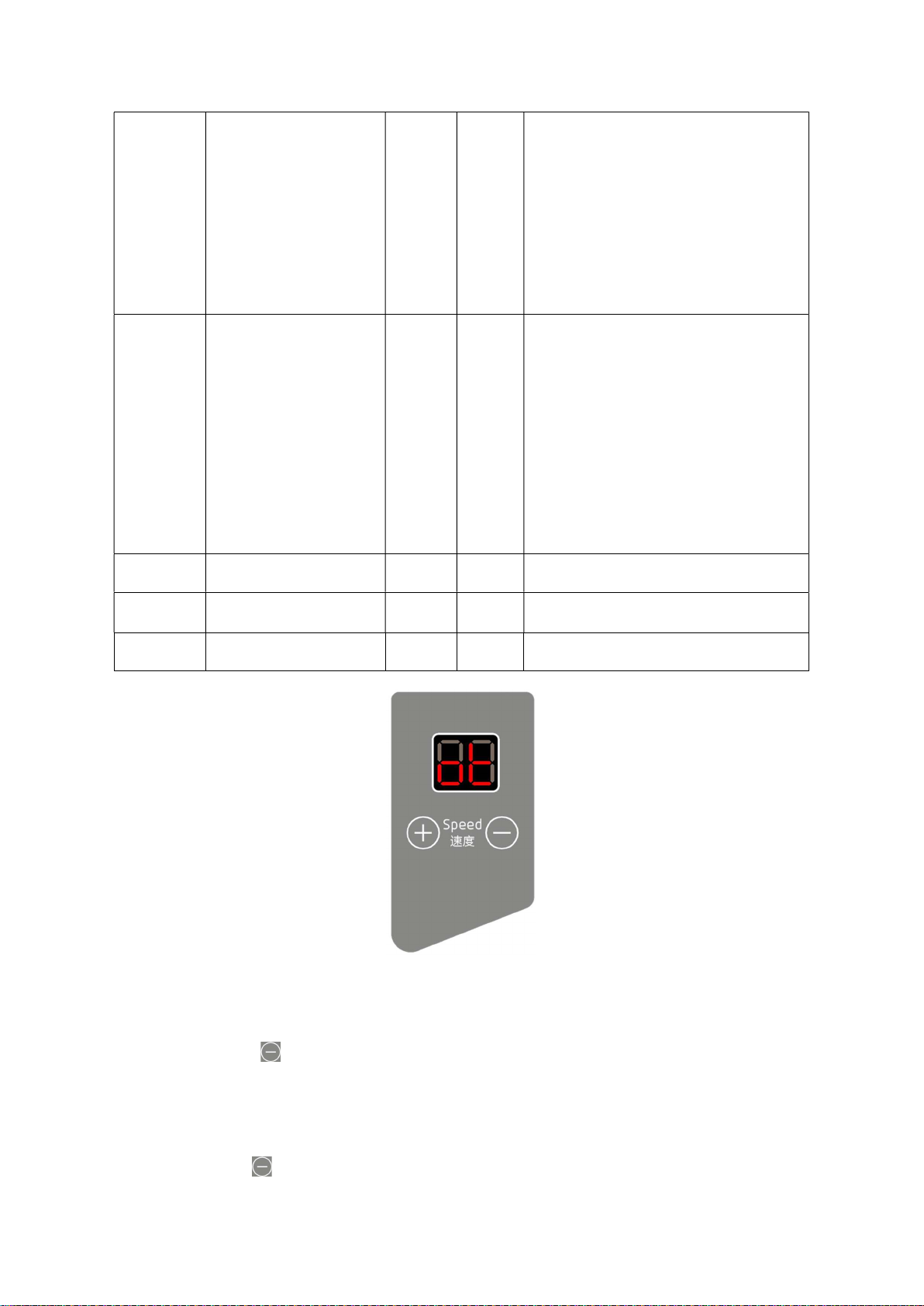
(if the positioner is damaged or the positioning function is not
required, when E5 is reported, press for 3S to close the
needle stop function).
E6 Abnormal speed
controller
If E6 alarm is flashing, please check if the speed controller's
type is match with the b parameter (default matching with the
computerized lockstitch machine type),and adjust the b
parameter to match with the current speed controller.
If E6 alarm is always on, please check whether the speed
controller is inserted and whether the plug-in / pin is loose or
falls off;
If the alarm cannot be eliminated, replace the governor; If the
alarm still cannot be eliminated, the signal of the control box
speed controller may be abnormal. Please contact the
maintenance personnel.
E7 Head safety switch
alarm
When the head safety switch is turned on, this alarm will
appear when the machine head dumps; Turn off the safety
switch or restore the head position. If the alarm cannot be
eliminated, please contact the maintenance personnel
EA Software over current
Please turn off the power and power on again. If the alarm
cannot be eliminated, please contact the maintenance
personnel.
Eb System overvoltage
Turn off the power supply immediately and check whether the
power supply voltage exceeds 294v (220V control box) / 147v
(110V control box). If so, please adjust the power supply
voltage to the rated voltage before starting the machine (220V
control box rated voltage: 220V, 110V control box rated
voltage: 110V).
EC System undervoltage
Immediately cut off the power supply and check whether the
power supply voltage is lower than 110V (220V control box) /
55v (110V control box). If so, please adjust the power supply
voltage to the rated voltage before starting the machine (220V
control box rated voltage: 220V, 110V control box rated
voltage: 110V).
EJ Current detection circuit
fault
Please check whether the circuit board is clean;
Please check whether the power supply voltage is normal;
Please wait for the power to be turned on / reset again (please
carefully check the functions of the power board).
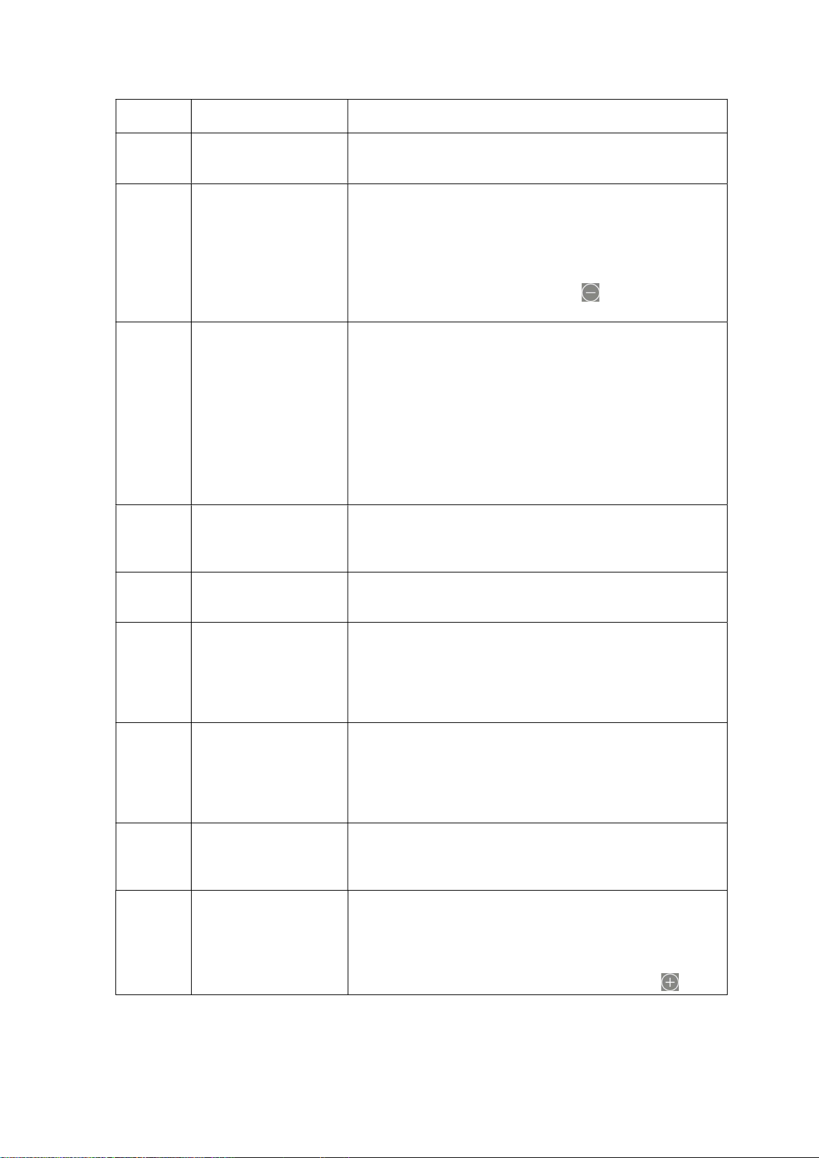
EZ Complementary stitch
button failure
Please check whether the complementary stitch button of the
machine head can be turn on and off normally. If it keep in off,
please replace the button of the machine head.
(the alarm will automatically turn off the complementary stitch
function, but will not affect the motor operation. The alarm
will be cleared automatically after 30s or by pressing )

Other manuals for F5

1

Other Jack Sewing Machine manuals

Jack JK-T718E Product guide

Jack

Jack JK-T718E Product guide

Jack A6F User manual

Jack

Jack A6F User manual

Jack F4 User manual

Jack

Jack F4 User manual

Jack JK-T781E User manual

Jack

Jack JK-T781E User manual

Jack JK-T1377E User manual

Jack

Jack JK-T1377E User manual

Jack JK-58420J Product guide

Jack

Jack JK-58420J Product guide

Jack T1310 User manual

Jack

Jack T1310 User manual

Jack A4 User manual

Jack

Jack A4 User manual

Jack E4 Series User manual

Jack

Jack E4 Series User manual

Jack JK-797 Product guide

Jack

Jack JK-797 Product guide

Jack C4 Installation guide

Jack

Jack C4 Installation guide

Jack A7 User manual

Jack

Jack A7 User manual

Jack JK-T5878-58G User manual

Jack

Jack JK-T5878-58G User manual

Jack JK-T781D User manual

Jack

Jack JK-T781D User manual

Jack K4-D Series User manual

Jack

Jack K4-D Series User manual

Jack A4 Product guide

Jack

Jack A4 Product guide

Jack JK-58420J Product guide

Jack

Jack JK-58420J Product guide

Jack JK-T1790 User manual

Jack

Jack JK-T1790 User manual

Jack A Series User manual

Jack

Jack A Series User manual

Jack QB/T2380-2013 User manual

Jack

Jack QB/T2380-2013 User manual

Jack A4 User manual

Jack

Jack A4 User manual

Jack JK-8995 User manual

Jack

Jack JK-8995 User manual

Jack JK-2284 Product guide

Jack

Jack JK-2284 Product guide

Jack F5 User manual

Jack

Jack F5 User manual

Popular Sewing Machine manuals by other brands

Brother CX205LA Operation manual

Brother

Brother CX205LA Operation manual

Brother LT2-B845 MKII Specifications

Brother

Brother LT2-B845 MKII Specifications

Bernina classic 1008 manual

Bernina

Bernina classic 1008 manual

Dürkopp Adler 888 instruction manual

Dürkopp Adler

Dürkopp Adler 888 instruction manual

Janome 234 Instruction book

Janome

Janome 234 Instruction book

Singer 143G2 Instructions for using and adjusting

Singer

Singer 143G2 Instructions for using and adjusting

JUKI AP-876/IP-420 instruction manual

JUKI

JUKI AP-876/IP-420 instruction manual

Singer 500 SERIES Instructions for using

Singer

Singer 500 SERIES Instructions for using

Janome MEMORY CRAFT 5200 - brochure

Janome

Janome MEMORY CRAFT 5200 - brochure

Janome HD9 Instruction book

Janome

Janome HD9 Instruction book

Singer QUANTUM 9920 Service manual

Singer

Singer QUANTUM 9920 Service manual

Janome S521 brochure

Janome

Janome S521 brochure

Brother LH4-B814-2 instruction manual

Brother

Brother LH4-B814-2 instruction manual

Singer 2273 instruction manual

Singer

Singer 2273 instruction manual

Reliable 7200SB instruction manual

Reliable

Reliable 7200SB instruction manual

Husqvarna Viking Opal 690Q user guide

Husqvarna Viking

Husqvarna Viking Opal 690Q user guide

Duerkopp Adler 743-121 installation instructions

Duerkopp Adler

Duerkopp Adler 743-121 installation instructions

White 1620 instruction manual

White

White 1620 instruction manual

manuals.online logo
manuals.online logoBrands
  • About & Mission
  • Contact us
  • Privacy Policy
  • Terms and Conditions

Copyright 2025 Manuals.Online. All Rights Reserved.