Harbor Freight Tools 95907 Parts list manual

6” OSCILLATING CAR FAN
Model
95907
ASSEMBLY AND OPERATION INSTRUCTIONS
Due to continuing improvements, actual product may differ slightly from the product described herein.
®
3491 Mission Oaks Blvd., Camarillo, CA 93011
Visit our website at: http://www.harborfreight.com
TO PREVENT SERIOUS INJURY, READ AND UNDERSTAND
ALL WARNINGS AND INSTRUCTIONS BEFORE USE.
Copyright©2007 by Harbor Freight Tools®. All rights reserved. No portion of this
manual or any artwork contained herein may be reproduced in any shape or form
without the express written consent of Harbor Freight Tools.
For technical questions or replacement parts, please call 1-800-444-3353.

Page 2SKU 95907 For technical questions, please call 1-800-444-3353.
SPECIFICATIONS
Material Steel Grill, thermoplastic and
ABS body
Overall Dimensions 8” L x 2” W x 11-1/2” H x 7-1/4”
diameter
Fan Size 6”
Clamp Opening Maximum 1-7/8”
Fuse F2A250V, 2 Amps, 250V
Power Source
12 VDC, 12 Watt Rated Power,
uses car or vehicle cigarette
igniter plug
RPM 3280~3780 RPM
Blade Fan I3
Power Cord Length 67”
Save This Manual
You will need this manual for the safety warnings and precautions, assembly, oper-
ating, inspection, maintenance and cleaning procedures, parts list and assembly diagram.
Keep your invoice with this manual. Write the invoice number on the inside of the front
cover. Write the product’s serial number in the back of the manual near the assembly dia-
gram, or write month and year of purchase if product has no number. Keep this manual
and invoice in a safe and dry place for future reference.
GENERAL SAFETY RULES
WARNING!
READ AND UNDERSTAND ALL INSTRUCTIONS
Failure to follow all instructions listed below may result in
electric shock, fire, and/or serious injury.
SAVE THESE INSTRUCTIONS
Keep your work area clean and well lit. Cluttered benches and dark areas invite
accidents.
Do not use this product in rain or wet conditions. Water entering this product
will increase the risk of electric shock.
Stay alert. Watch what you are doing, and use common sense when using this
product. Do not use this product while tired or under the influence of drugs,
alcohol, or medication. A moment of inattention while operating this product may
result in serious personal injury.
1.
2.
3.

Page 3SKU 95907 For technical questions, please call 1-800-444-3353.
Keep out of the reach of any children. A responsible adult should be present if
children are in the area while the Car Fan is being used.
Do not force the Car Fan. Use the correct Car Fan for your application. The
correct Car Fan will do the job better and safer at the rate for which it is designed. Do
not force the Car Fan and do not use it for a purpose for which it is not intended.
Do not use the Car Fan if the Speed Control Switch does not turn it on or off.
Any product that cannot be controlled with the Speed Control Switch is dangerous
and must be replaced.
Disconnect the Power Cord Plug from the power source before making any
adjustments, changing accessories, or storing the Car Fan. Always unplug
the Car Fan from its electrical outlet before performing any inspection, main-
tenance, or cleaning procedures.
Store an idle Car Fan out of reach of children and other untrained persons.
This product is dangerous in the hands of untrained users.
Check for breakage of parts, and any other condition that may affect the Car
Fan’s operation. If damaged, have it serviced before using. Many accidents
are caused by poorly maintained products.
Product service must be performed only by qualified repair personnel. Service
or maintenance performed by unqualified personnel could result in a risk of injury.
When servicing this product, use only identical replacement parts. Follow
instructions in the “Inspection, Maintenance, And Cleaning” section of this
manual. Use of unauthorized parts or failure to follow maintenance instructions
may create a risk of electric shock or injury.
Maintain labels and nameplates on the product. These carry important informa-
tion. If unreadable or missing, contact Harbor Freight Tools for a replacement.
Never leave the Car Fan unattended when it is plugged in. Turn off the Car
Fan, and unplug it from its electrical outlet before leaving.
Do not allow the Car Fan to be exposed to fire as this may result in an
explosion.
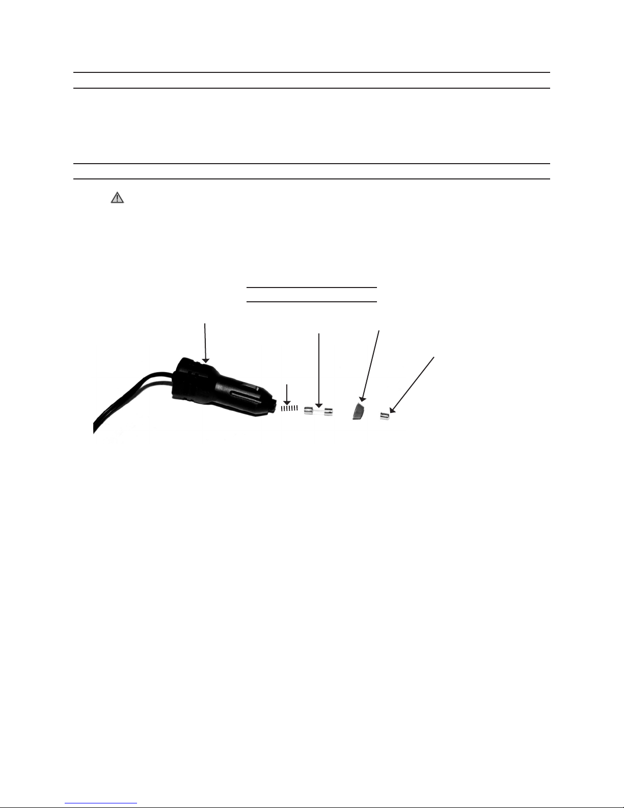
Only plug into a DC12V Cigarette Lighter Adapter receptacle.
Do not block air vents. The Speed Control Switch Box gets hot when operat-
ing, and blocking the vents will cause overheating resulting in explosion or
injury.
4.
5.
6.
7.
8.
9.
10.
11.
12.
13.
14.
15.
16.

Page 4SKU 95907 For technical questions, please call 1-800-444-3353.
UNPACKING
When unpacking, check to make sure that the item is intact and undamaged. If any
parts are missing or broken, please call Harbor Freight Tools at the number shown on the
cover of this manual as soon as possible.
ASSEMBLY INSTRUCTIONS
WARNING! Make sure the Speed Control Switch of the Car Fan is in its “OFF”
position and that it is unplugged from its electrical outlet before making any adjust-
ments to the Car Fan.
Your 6” Oscillating Car Fan comes completely assembled. Instructions on replacing
the Blade and Fuse are outlined below.
Replacing the Fuse
Cigarette Plug (1) Fuse (27) Cap (29)
Leader (28)
Figure 1
Spring (30)
If the Car Fan fails to operate when plugged into the cigarette lighter adapter re-
ceptacle, the Fuse (27) should be changed.
Unscrew the Cap (29) from the Cigarette Plug (1) as shown in Figure 1.
Pull out the Fuse (27) from the Cigarette Plug (1). The Fuse compartment also
includes one Spring (30), and the Leader (28) which will also come out when re-
moving the Fuse (27).
The Fuse (27) is a F2A250V amp fuse. Do not replace with a different size fuse,
as this may result in excessive heat and explosion, which can damage the Car Fan
and cause injury.
Insert the Spring (30), and replace the Fuse (27). Set the Leader (28) over the
Fuse and into the Cap (29) of the Cigarette Plug (1). Screw Cap (29) back onto
the Cigarette Plug (1).
1.
2.
1.
2.
3.
4.
5.

Page 5SKU 95907 For technical questions, please call 1-800-444-3353.
Replacing the Fan Blade
WARNING! Make sure the Speed Control Switch is in its “OFF” position and that
the Car Fan is unplugged from its power source before performing any inspection,
maintenance, or cleaning procedures.
Pull off the Rubber Ring (12) separating the Rear Steel Grill (9) and Front Steel Grill
(13). Pull off the Front Steel Grill (13).
Pull the Fan Blade (11) straight out to remove it. Press the new Fan Blade (11)
back into place. Replace the Front Steel Grill (13) and slide the Rubber Ring (12)
back into place.
Mounting the Speed Control Switch
The Car Fan Speed Control Switch (2) can be mounted to the vehicle as desired
(hardware not included).
Make certain that all drilling paths are clear of electrical lines, cables, wire and any
other obstructions.
Make certain that there is sufficient length in the Power Cord (3) to reach from the
Cigarette lighter to the location of the Speed Control Switch (2).
Use the Speed Control Switch as as template to mark two holes in the desired
surface. Drill holes in the desired surface.
Align the holes in the Speed Control Switch (2) with the drilled holes. Mount the
Speed Control Switch (2) using hardware (not included) of a sufficient length and
strength. The screws used must be able to fully secure the Speed Control Switch
in place.
1.
2.
3.
1.
2.
3.
4.
5.

Page 6SKU 95907 For technical questions, please call 1-800-444-3353.
OPERATION INSTRUCTIONS
Setting Fan Speed
Oscillation Lever
Butterfly Nuts (26)
Clip
Figure 2
The Speed Control Switch (2) turns the Car Fan power ON and Off by setting the
Switch to the center position.
The fan speed can be set to either FAST or SLOW by moving the Speed Control
Switch to the side marked with the corresponding speed.
Setting Fan Position and Oscillating Control
Grasp the Clip and squeeze to open the end. Slide the open end of the Clip onto
the object the Car Fan will be attached to. Make certain the Clip slides fully onto
the object.
Move the Oscillating Lever to the “Unlock” position to allow the Fan to oscillate. Set
the lever to the “Locked” position to have the Fan stay in one position.
The Motor Housing (6) and the Connector (16) can all be rotated to set the Fan to
different angles as desired.
Loosen the Butterfly Nuts (26). Move the Fan to the desired position. Tighten the
Butterfly Nuts back into place.
To operate the Car Fan, plug the Cigarette Plug (1) into the lighter plug receptacle
of your vehicle. Leave it plugged in while using the Car Fan from your vehicle.
Do not leave the Car Fan running if your leave the area.
1.
2.
1.
2.
3.
4.
5.
6.

Page 7SKU 95907 For technical questions, please call 1-800-444-3353.
INSPECTION, MAINTENANCE, AND CLEANING
WARNING! Make sure the Speed Control Switch is in its “OFF” position and that
the Car Fan is unplugged from its power source before performing any inspection,
maintenance, or cleaning procedures.
BEFORE EACH USE, inspect the general condition of the Car Fan. Check for loose
screws, misalignment or binding of moving parts, cracked or broken parts, damaged
electrical wiring, and any other condition that may affect its safe operation. Do not
use damaged equipment.
When not in use, store the Car Fan in a dry location out of direct sunlight.
Keep the Car Fan out of the reach of children.
Clean with a soft cloth. Do not use flammable liquids or harsh detergents to
clean the Car Fan. Do not submerge in fluid to clean.
To clean the Fan Blade (11), see instructions for replacing the Fan Blade (11)
on page 4.
1.
2.
3.
4.
5.
THE MANUFACTURER AND/OR DISTRIBUTOR HAS PROVIDED THE PARTS LIST AND ASSEM-
BLY DIAGRAM IN THIS MANUAL AS A REFERENCE TOOL ONLY. NEITHER THE MANUFACTURER
OR DISTRIBUTOR MAKES ANY REPRESENTATION OR WARRANTY OF ANY KIND TO THE BUYER
THAT HE OR SHE IS QUALIFIED TO MAKE ANY REPAIRS TO THE PRODUCT, OR THAT HE OR
SHE IS QUALIFIED TO REPLACE ANY PARTS OF THE PRODUCT. IN FACT, THE MANUFACTURER
AND/OR DISTRIBUTOR EXPRESSLY STATES THAT ALL REPAIRS AND PARTS REPLACEMENTS
SHOULD BE UNDERTAKEN BY CERTIFIED AND LICENSED TECHNICIANS, AND NOT BY THE
BUYER. THE BUYER ASSUMES ALL RISK AND LIABILITY ARISING OUT OF HIS OR HER REPAIRS
TO THE ORIGINAL PRODUCT OR REPLACEMENT PARTS THERETO, OR ARISING OUT OF HIS
OR HER INSTALLATION OF REPLACEMENT PARTS THERETO.
PLEASE READ CAREFULLY

Page 8SKU 95907 For technical questions, please call 1-800-444-3353.
ASSEMBLY AND PARTS DIAGRAM
29
28
27
30
1
2
4568 9 10 11
7 12 13
14
15
16
18
17
20
21
22
23
24
25
26
19
3
Description
1 Cigarette Plug 1
2 Speed Control Switch 1
3 Power Cord 1
4 Rear Cover 1
5 Motor Shaft Bushing 1
6 Motor Housing 1
7 Motor 1
8 Cross Screw 2
9 Rear Steel Grill 1
10 Self Taping Screw 4
11 Fan Blade 1
12 Rubber Ring 1
13 Front Steel Grill 1
14 Long Shaft 1
15 Non Slip Plate
Description
16 Connector 1
17 Screw 2
18 Bracket 1
19 Base 1
20 Upper Clip 1
21 Non Slip Pad 8
22 Lower Clip 1
23 Bolt 1
24 Nut 1
25 Spring for Clip 1
26 Butterfly Nut 2
27 Fuse 2A250V 1
28 Leader 1
29 Cap 1
30 Spring 1
Table of contents
Other Harbor Freight Tools Fan manuals

Harbor Freight Tools
Harbor Freight Tools 98625 User manual

Harbor Freight Tools
Harbor Freight Tools 47755 User manual

Harbor Freight Tools
Harbor Freight Tools 66950 Installation manual

Harbor Freight Tools
Harbor Freight Tools 57896 Assembly instructions

Harbor Freight Tools
Harbor Freight Tools 66471 Installation manual