Harison DISCOVER 1049 User manual

Operation Manual

Catalogue
Key Knowledge for Safety.................................................................................................... 1
Assembly Drawing...........................................................................................................2-3
List of Spare Parts............................................................................................................4-5
Assembly Instructions.....................................................................................................6-22
Training Guidance.............................................................................................................23
Chart of Training Guidance............................................................................................24-25
Warning........................................................................................................................26

Key Knowledge for Safety
Please keep this manual well for future reference.
Matters to be attended:
There are some safety precautions to be followed during the operation although the safety
considerations have been taken into consideration in the design and manufacture of this training
machine. Please read this manual carefully before assembling and using the training machine,
especially the following safety precautions:
1. 1.Keep the children and pets away from the training machine, and do not leave any
unattended child alone in the room where the training machine is placed.
2. Only one person is allowed to use the training machine at the same time.
3.Any user who feeling dizziness, nausea, chest tightness or other uncomfortable symptom
shall stop the training immediately and visit a doctor thereafter.
4. The training machine shall be placed on a clean and flat surface, and shall be not used at
any place near the water source or outdoor.
5.Hands shall be not close to any transmission parts when using.
6.Users are required to dress appropriately for training when using the training machine and
no loose or other types of clothing that may get stuck during training is allowed. Users are also
recommended to wear sneakers or healthcare shoes during training.
7.The training shall be carried out only in the way described in the instructions during the use
of the training machine , and no training shall be carried out in any manner outside the
instructions.
8.Any object with with a sharp point around the training machine is not allowed.
9.No disabled person shall use the training equipment without the supervision of a training
partner or a caregiver.
10.Usually, users are required to warm up before training through a variety of stretching
exercises.
11. No use is allowed upon any abnormality of the training machine
12.Training records shall be kept during the training process.
13.The maximum user weight of this product is 120KG.
14.The maximum allowable weight of this product to hold is 72KG (with weights).
15.The general safety standard of this product is: GB17498.1-2008/GB17498. 2-2008.
Warning:
It is especially important for users who are over the age of 35 or has medical records to
consult a doctor before training. Please read all instructions carefully before using any fitness
equipment. We will not be responsible for any injury caused by the user themselves.
1
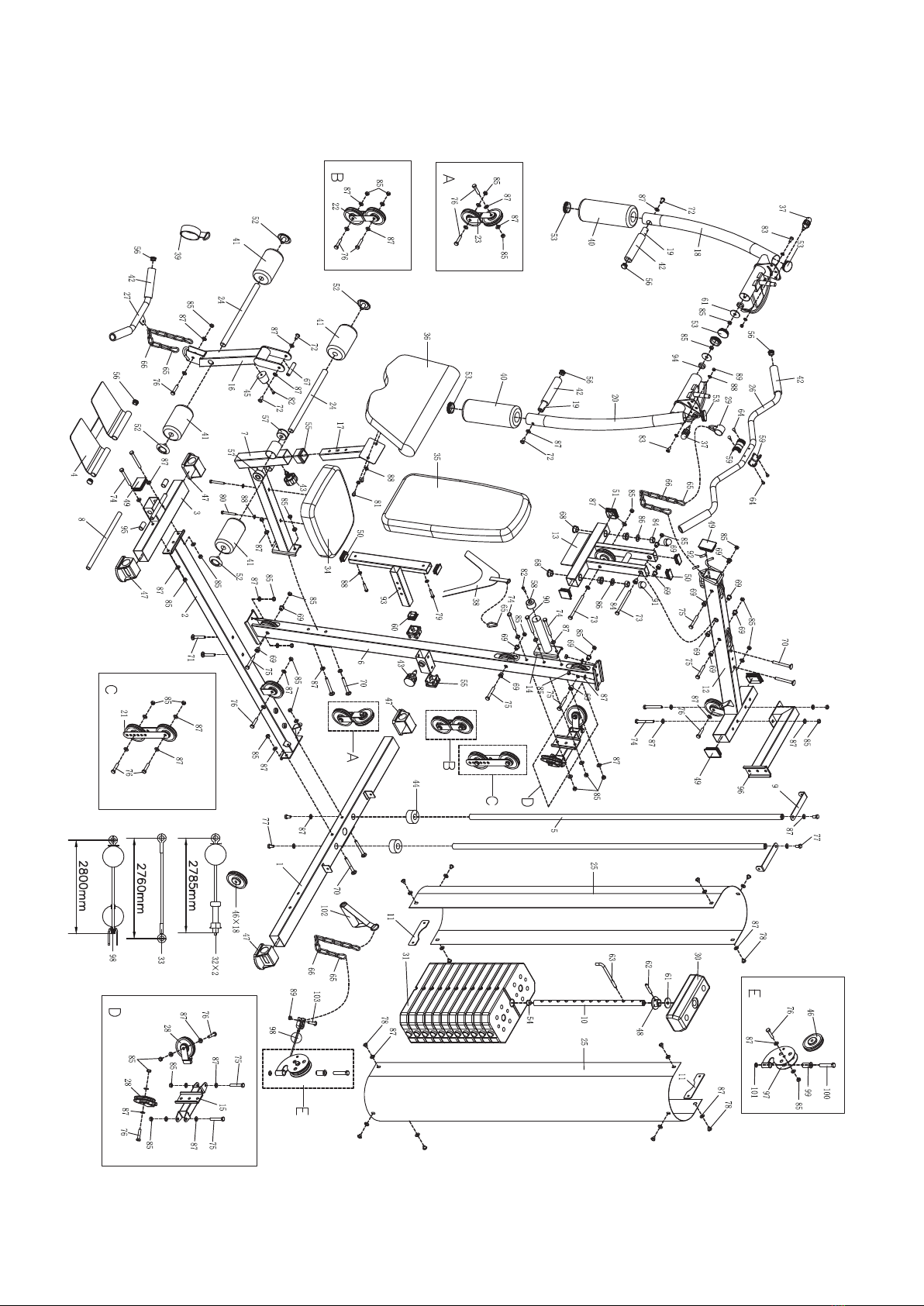
Assembly Drawing
A
2
B
3

List of Spare Parts
A- List of Spare Parts
Item Desc.& Spec. Qty. Item Desc.& Spec. Qty.
1 Rear bottom tube assembly 1 53 50 Circular tube plug 6
2 Floor tube assembly 1 54 Spherical circular tube plug 1
3 Front floor tube assembly 1 55 Tube lining 3
4 Pedal 1 56 25 Circular tube plug 8
5 Counterweight guide rod weldment 2 57 Plastic sleeve 2
6 Front inclined tube assembly 1 58 Forward cushion 1
7 Front strain-frame supporting tube
assembly
1 59 Circular tube sleeve 4
8 Limiting tube assembly 1 60 38 square tube plug 1
9 Shield connection plate 1 2 61 Adjusting rod flat gasket 3
10 Weight adjusting rod assembly 1 62 Cylindrical pin 1
11 Shield connection plate 2 2 63 L-shape bolt 1
12 Top beam assembly 1 64 Core pulling rivet 4
13 Cantilever assembly 1 65 Shackle 7
14 Limiting tube assembly 1 66 Eight-ring chain 3
15 U-seat connecting tube assembly 1 67 Shaft 1
16 Kick assembly 1 68 Pulley pressing sleeve(large) 4
17 Hand pad assembly 1 69 Pulley pressing sleeve(small) 16
18 Right arm swinging assembly 1 70 Pan head square neck bolt(M10*90) 6
19 Forward pushing handle assembly 2 71 Pan head square neck bolt(M10*65) 2
20 Left arm swinging assembly 1 72 Hexagonal socket head bolt 4
21 Pulley connection plate 2 73 Hexagon bolt (M10*135) 2
22 Double U-seat weldment 1 74 Hexagon bolt (M10*90) 4
23 Rotary U-seat 1 75 Hexagon bolt (M10*65) 8
24 Sponge stick tube 2 76 Hexagon bolt (M10*45)11
25 Iron-net protective cover 2 77 Hexagon bolt (M10*20) 4
26 High tension handlebar tube assembly 1 78 Hexagonal socket head bolt
(M10*12)
12
27 Low tension handlebar tube assembly 1 79 Hexagon bolt (M10*40) 2
28 Arm swinging U-seat assembly 2 80 Hexagon bolt (M8*65)2
29 High tension sleeve weldment 1 81 Hexagon bolt (M8*15) 2
30 Weight heads 1 82 Cross recess pan head screw
(M6*20)
2
31 Weight 11 83 Hexagon bolt M8*25 2
32 High tension wire assembly 2 84 Locknut(M16) 2
33 Butterfly arm wire assembly 1 85 Locknut(M10) 38
34 Seat cushion component 1 86 Big flat gasket (D16) 2
35 Back cushion component 1 87 Flat gasket(D10) 72
36 Hand pad component 1 88 Flat gasket(D8) 10
4

37 Small elastic pin knob 2 89 Locknut M8 3
38 Training rope assembly 1 90 Hexagon bolt (M10*95)1
39 Round tape assembly 1 91 Nut cap (M16) 2
40 Big sponge stick 2 92 High tension PVC sleeve 2
41 Sponge stick 4 93 Back cushion adjusting tube l
42 Sponge grip 6 94 Spacer bush 2
43 Elastic pin knob 2 95 PVC plastic sleeve 2
44 Shock pad 2 96 Top tube connection weldment 1
45 Kick cushion 1 97 Pulley yoke weldment 1
46 Pulley 18 98 Handle wire assembly (2800mm) 1
47 Outer foot strap 4 99 Spacer tube 1
48 Weight head bush 1 100 Hexagon bolt (M12*90)1
49 50* 50 rectangular tube plug 4 101 Flat gasket (D12) 1
50 25* 50 rectangular tube plug 4 102 Handle component 1
51 50 square tube plug 2 103 Hexagonal socket head bolt (M8*35) 1
52 25 circular tube plug 4 104
Tool
Spanner 13, 14 and 17 2 Allen wrench 6# 2
Special spanner 1 Allen wrench 5# 1
B- List of Spare Parts
Item Desc.& Spec. Qty. Item Desc.& Spec. Qty.
l Parallel bars lower supporting frame 1 14 Hexagon bolt (M10*70) 2
2 Parallel bars upper supporting frame 1 15 Hexagon bolt (M10*20) 4
3 Parallel bars left arm-resting tube 1 16 Square neck pan bolt (M10*70) 2
4 Parallel bars right arm-resting tube 1 17 Hexagon bolt (M8*70) 2
5 Arm-resting standpipe 2 18 Hexagon bolt (M8*65)4
6 Backrest assembly 1 19 Hexagon bolt (M8*25) 2
7 Hand pad assembly 2 20 Flat gasket(D10)14
8 Handle grip (D25) 4 21 Flat gasket(D8) 8
9 Circular tube plug (D25) 6 22 Locknut(M10)6
10 Hollow plug 2 23
11 25* 50 rectangular tube plug 1 24
12 50 square tube plug 1 25
13 Hexagon bolt (M10*95)2 26
5
Assembly Instructions
Installation Instructions for Body Section(A)
Important: Please make sure that all the accessories are complete after unpacking.
Remark: It is better for two or more people to assemble together during the assembly process to
avoid any injury.
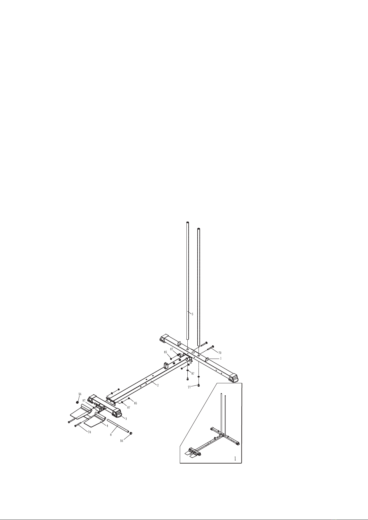
Step1
1.Place the rear bottom tube assembly (1) and floor tube assembly (2) as shown in the figure
and secure them with M10*90 pan head square neck bolt (70), D10 flat gasket (87) and M10
locknut (85).
2. Insert the counterweight guide rod weldment (5) into the hole corresponding to the rear
bottom tube assembly (1), and lock it from the bottom with M10*20 hexagon bolt (77) and D10
flat mat (87) after fitting.
3. Place the floor tube assembly (2) and the front floor tube assembly (3) as shown in the
figure and secure them with M10*90 hexagon bolt (74), D10 flat gasket (87) and M10 locknut
(85).
4. Fix the limiting tube (8) through the pedal (4) as shown on the front floor tube assembly (3)
and then cover both ends of the limiting tube (8) with a D25 circular tube plug (56).
6

Step2
1.Place the front inclined tube assembly (6) on the assembled floor tube assembly (2) as
shown in the figure and secure it with M10*65 pan head square neck bolt(71), D10 flat gasket (87)
and M10 locknut (85).
2.Place the front bottom bracket support tube assembly (1) and the front inclined tube
assembly (6) as shown in the figure and secure them with M10*90 pan head square neck bolt (70),
D10 flat gasket (87) and M10 locknut (85).
7
Step3
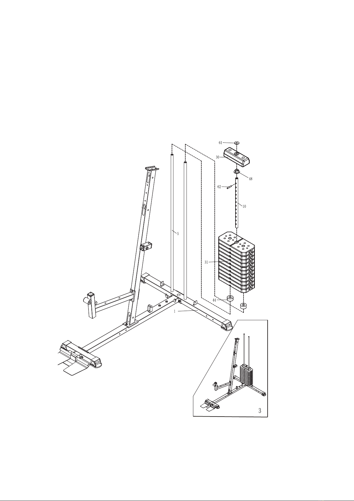
1.First, load the shock pad (44) and the weight (31) into the counterweight guide rod
weldment (5) as shown in the figure, them insert it in the direction shown. Lead the cylindrical
pin(62) through the first hole (from top to bottom) of the weight head bush (48) and the weight
adjusting rod assembly (10), and then install the weight head assembly (30). At last, place the
adjusting rod flat gasket (61) in the position shown in the figure.
8
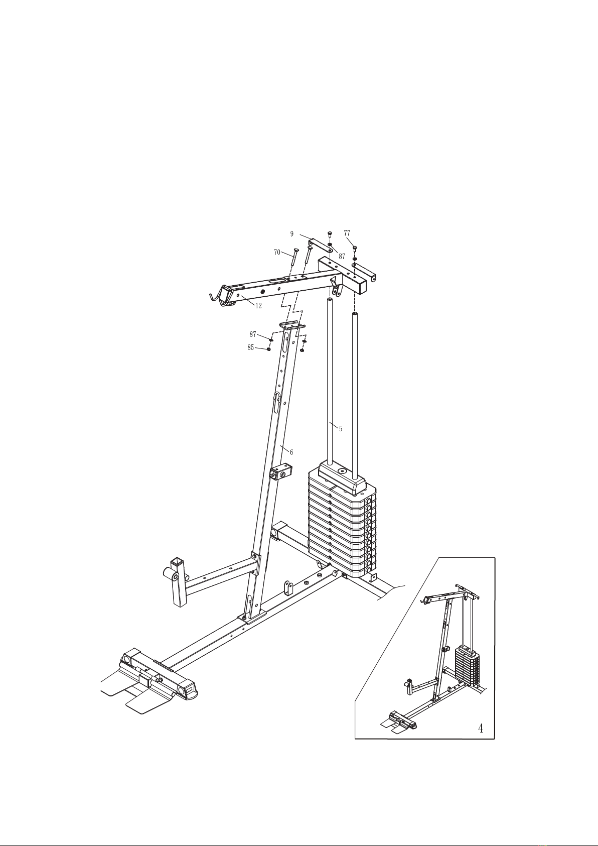
Step4
1.Align the holes on the cross pipe on the top beam assembly (12) with the counterweight
guide rod weldment (5), then lock the M10*20 hexagon bolt(77), D10 flat gasket (87) and shield
connection plate1(9) in from the top, and do not lock it for the time being. Align the top beam
assembly (12) with the hole of the front inclined tube assembly (6) as shown in the figure and
secure it with M10*90 pan head square neck bolt(70), D10 flat gasket (87) and M10 locknut (85).
9
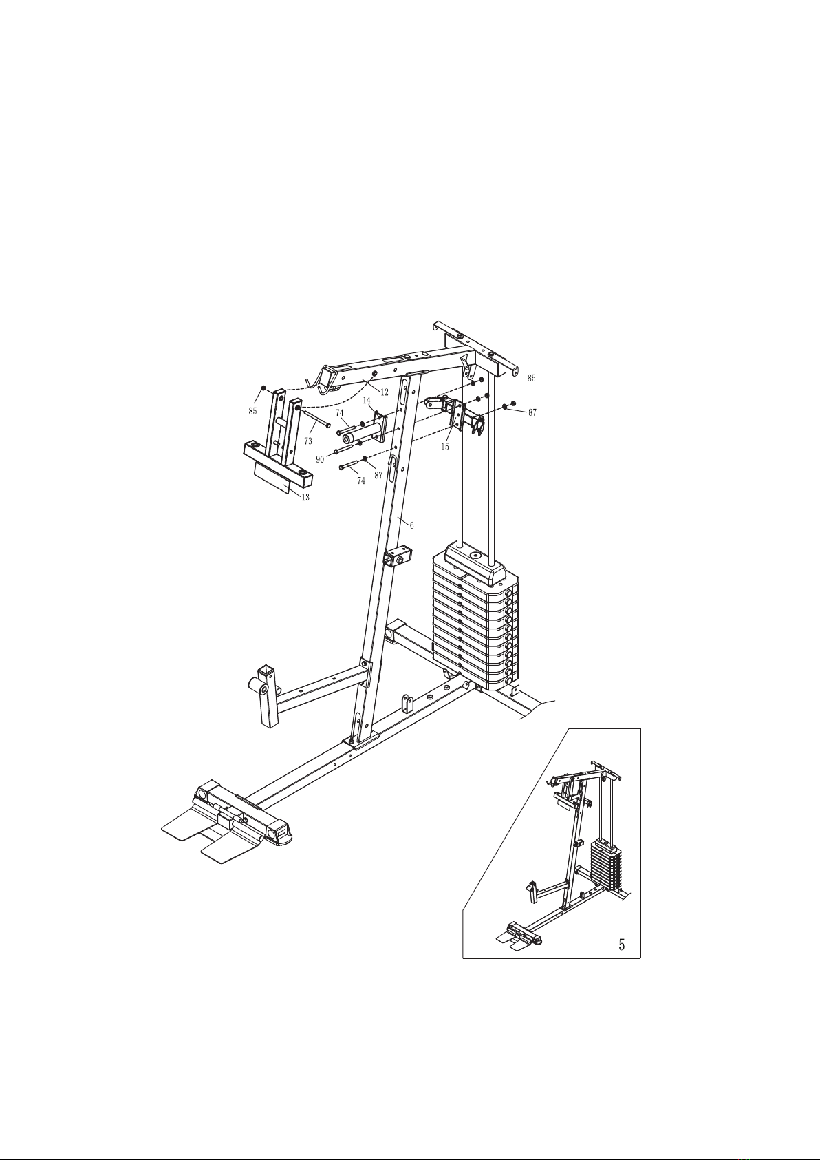
Step5
1.Place the limiting tube assembly (14), front inclined tube assembly (6), U-seat connecting
tube assembly (15) as shown in the figure and secure them with M10*95 hexagon bolt (90),
M10*90 hexagon bolt (74), D10 flat gasket (87) and M10 locknut (85).
1.Assemble the cantilever assembly (13) into the hole corresponding to the top beam
assembly (12) as shown in the figure, and lock and fix it with M10*135 hexagon bolt (73) and
M10 locknut (85).
10
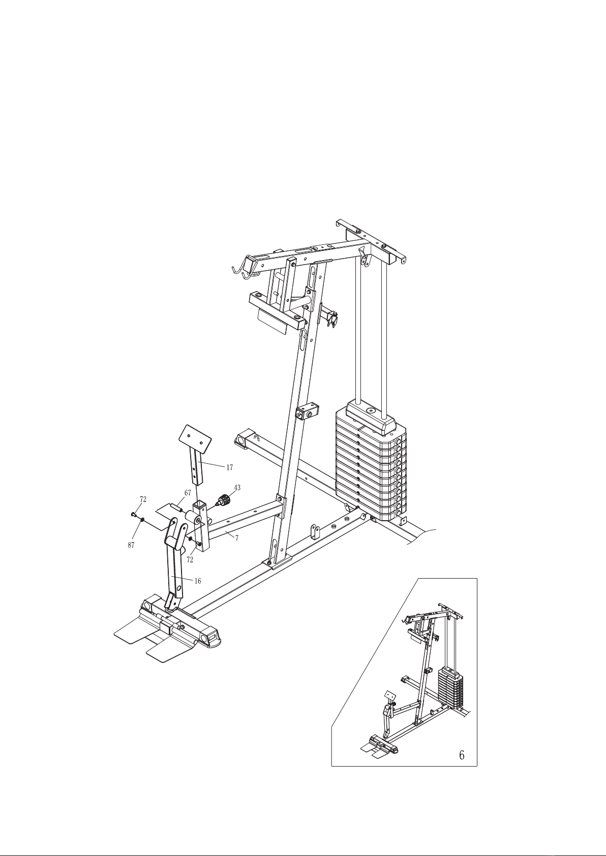
Step6
1.Insert the shaft (67) into the front bottom bracket support tube assembly (7) as shown in the
figure, then align the kick assembly (16) with the front bottom bracket support tube assembly (7)
as shown, and secure with M10*20 hexagonal socket head bolt (72) and D10 flat gasket (87).
2.Insert the hand pad assembly (17) into the front bottom bracket support tube assembly (7)
as shown in the figure and secure it with the elastic pin knob (43).
11
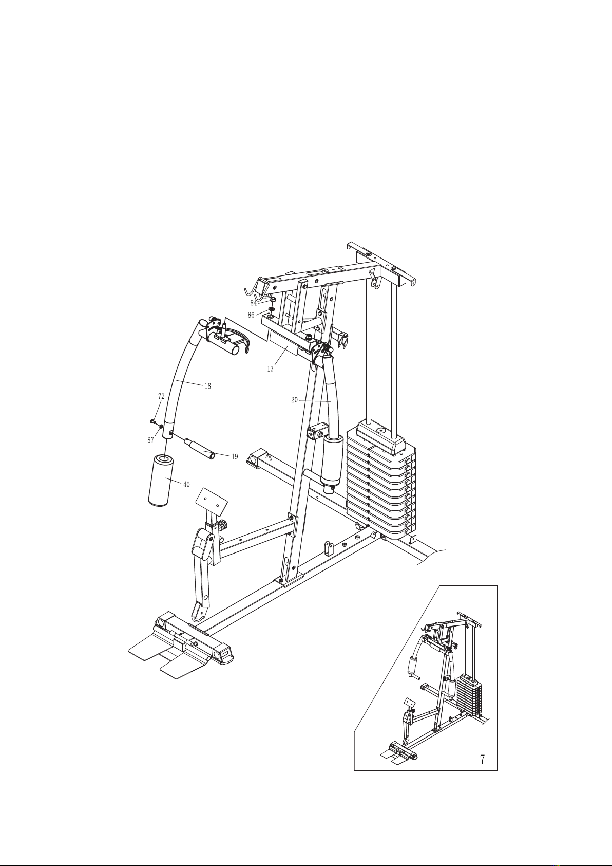
Step7
1.Assemble the right arm swinging assembly (18) and the left arm swinging assembly (20) on
the hole corresponding to the cantilever assembly (13) as shown in the figure, and lock and fix
them with M16 locknut (84) and D16 big flat gasket (86).
2.Assemble the big sponge stick (40) on the right arm swinging assembly (18) and left arm
swinging assembly (20) as shown in the figure.
1.Lead the forward pushing handle assembly (19) through the hole corresponding to the right
arm swinging assembly (18) and left arm swinging assembly (20), and fix it with M10*20
hexagon socket pan head bolt (72) and D10 big flat gasket (87).
12
Step8
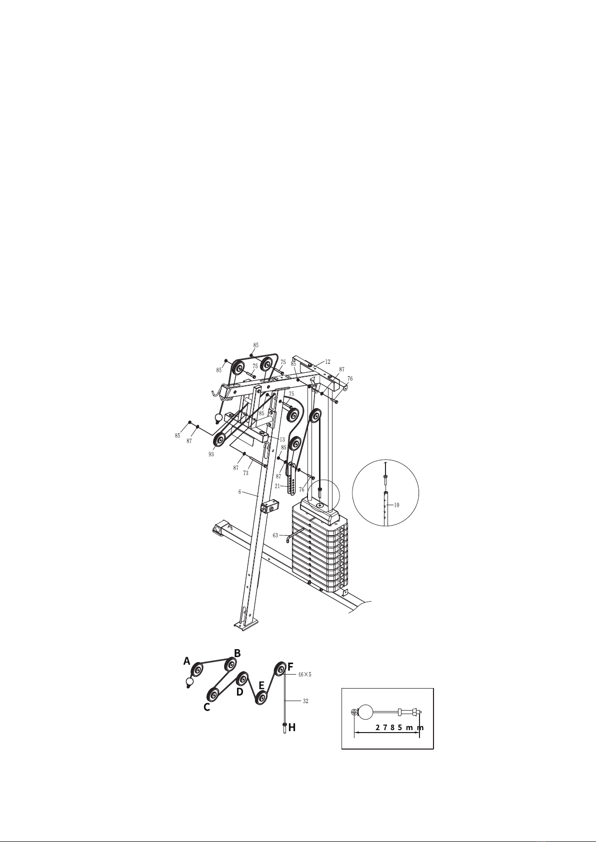
1.Take the wire (32) out and assemble it according to the sequence in the figure after
placement
2.Assembly pulley A, B and D in the same manner as shown in the figure, of which the
sequence is M10*65 hexagon bolt (75), pulley assembly (46), and M10 locknut (85).
3.As shown in Figure C, fix the M10* 135 hexagon bolt (73), D10 flat gasket (87), pulley
assembly (46), D10 flat gasket (87), and M10 locknut (85) on the cantilever assembly (13);
4.As shown in Figure E, the sequence is M10*45 hexagon bolt (76), D10 flat gasket (87),
pulley connection plate (21), pulley (46), pulley connection plate (21), D10 flat gasket (87)
and M10 locknut (85);
5. As shown in Figure F, fix the M10*45 hexagon bolt (76), D10 flat gasket (87), pulley (46),
D10 flat gasket (87) and M10 locknut (85) on the top beam assembly (12).
6.As shown in Figure H, lock the other end of the wire (32) on the weight adjusting rod
assembly (10) and insert the L-shape bolt (63) into the counterweight block.
13

Step9
1.Take the wire (98) out and assemble it according to the sequence as shown in the figure after the
placement;
2.As shown in Figure A, following the sequence of M10*65 hexagon bolt (75), pulley (46), and
M10 locknut (85)and fix them in the front inclined pipe assembly (6);
3. As shown in Figure B, following the sequence of M10*45 hexagon bolt (76), D10 flat gasket
(87), pulley assembly (46), D10 flat gasket(87) and M10 locknut (85) and fix them on the double
U-shape seat weldment (22);
4. As shown in Figure C, following the sequence of M10*45 hexagon bolt (76), D10 flat gasket
(87), pulley connection plate (21), pulley assembly (46), pulley connection plate (21), D10 flat
gasket (87), and M10 locknut (85) to assemble;
5. As shown in Figure D, install the pulley yoke weldment (97) on the floor tube assembly (2) with
hexagon bolt M12*90 (100) through the spacer tube (99) and D12 flat gasket (101), then lead the
wire (98) through the pulley yoke weldmentr (97) and fix the M8*35 hexagonal socket head
bolt(103) and M8 locknut (89) as shown in the figure.
21
21
2
6
98
46×3
75
85
76
87
85
87
76
85
98
100
99
97
101
98
89
103
14

Step10
1.Take the butterfly arm wire (33) out and assemble according to the sequence as shown in
the figure after placement;
2. As shown in Figure A and E, hang both ends of the wire (33) in the right arm swinging
assembly (18) and the left arm swinging assembly (20);
3. As shown in Figure B and Figure D, follow the sequence of M10*45 hexagon bolt (76),
D10 flat gasket (87), pulley assembly (46), D 10 flat gasket (87), M10 locknut (85) and fix
them on the U-seat connecting tube assembly (15);
4. As shown in Figure C, follow the sequence of M10*45 hexagon bolts (76), D10 flat gasket
(87), pulley (46), D10 flat gasket (87) and M10 locknut (85) , and fix them on the rotary U-seat
(23)
15
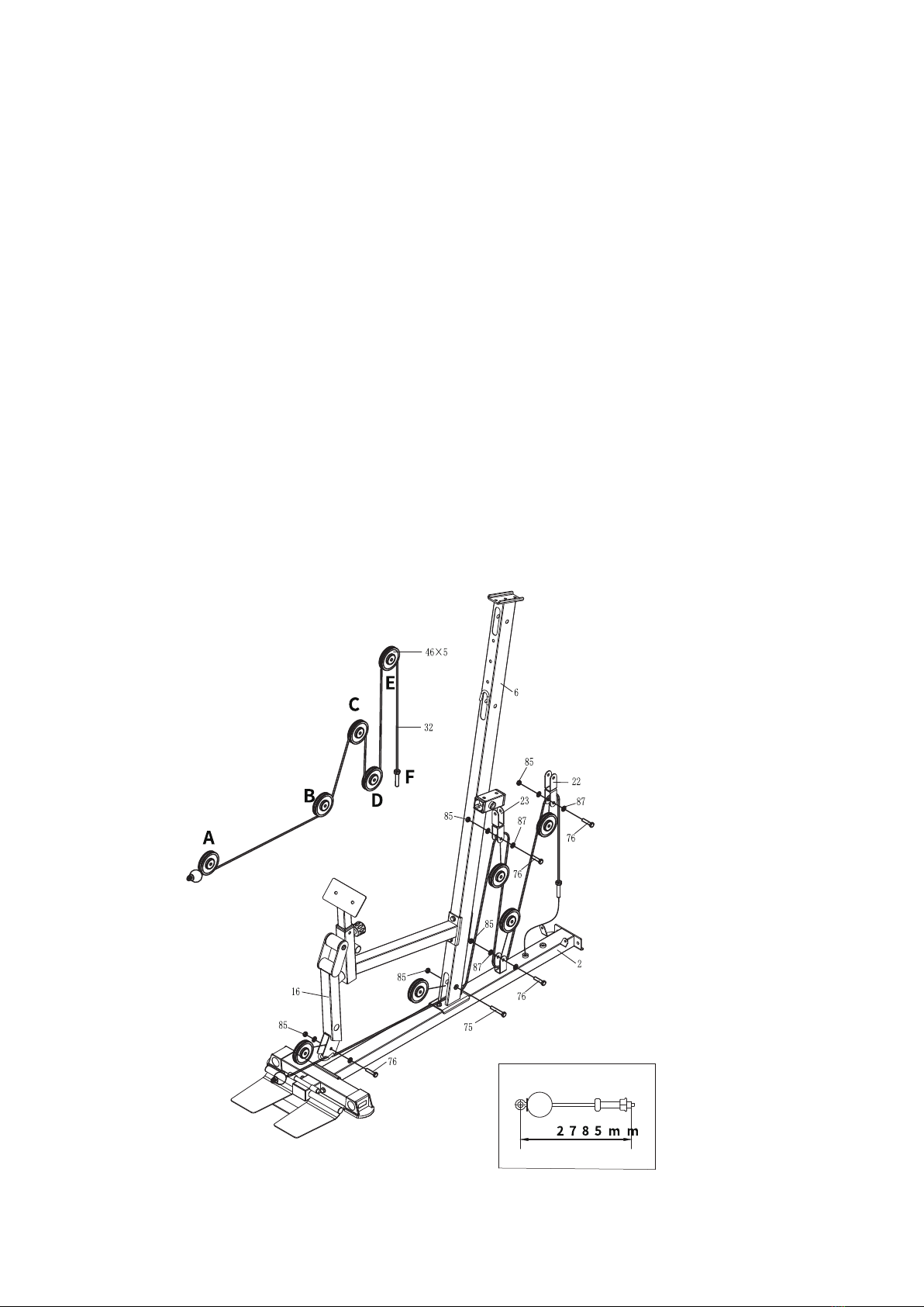
Step11
1.Take the wire (32) out and assemble it according to the sequence in the figure after
placement
2. As shown in Figure A, follow the sequence of M10*45 hexagon bolt (76), D10 flat gasket
(87), pulley component (46), D10 flat gasket (87), and M10 locknut (85) and fix them in the kick
assembly (16);
3. As shown in Figure B, follow the sequence of M10*65 hexagon bolt (75), pulley assembly
(46), and M10 locknut (85) and fix them in the front inclined tube assembly (6);
4. As shown in Figure C, follow the sequence of M10*45 hexagon bolt (76), D10 flat gasket
(87), pulley component (46), D10 flat gasket (87) and M10 locknut (85) and fix them on the rotary
U-seat (23);
5. As shown in Figure D, follow the sequence of M10*45 hexagon bolt (76), D10 flat
gasket (87), pulley assembly (46), D10 gasket (87), and M10 locknut (85) and fix them in the
floor tube assembly (2);
6. As shown in Figure E, follow the sequence of M10*45 hexagon bolt (76), D10 flat
gasket (87), pulley connection plate (21), pulley assembly (46), pulley connection plate (21), D10
flat gasket (87) and M10 locknut (85) to fix.
7. Fasten the other end of the wire (32) to the floor tube assembly (2) as shown in Figure F.
16
Step12
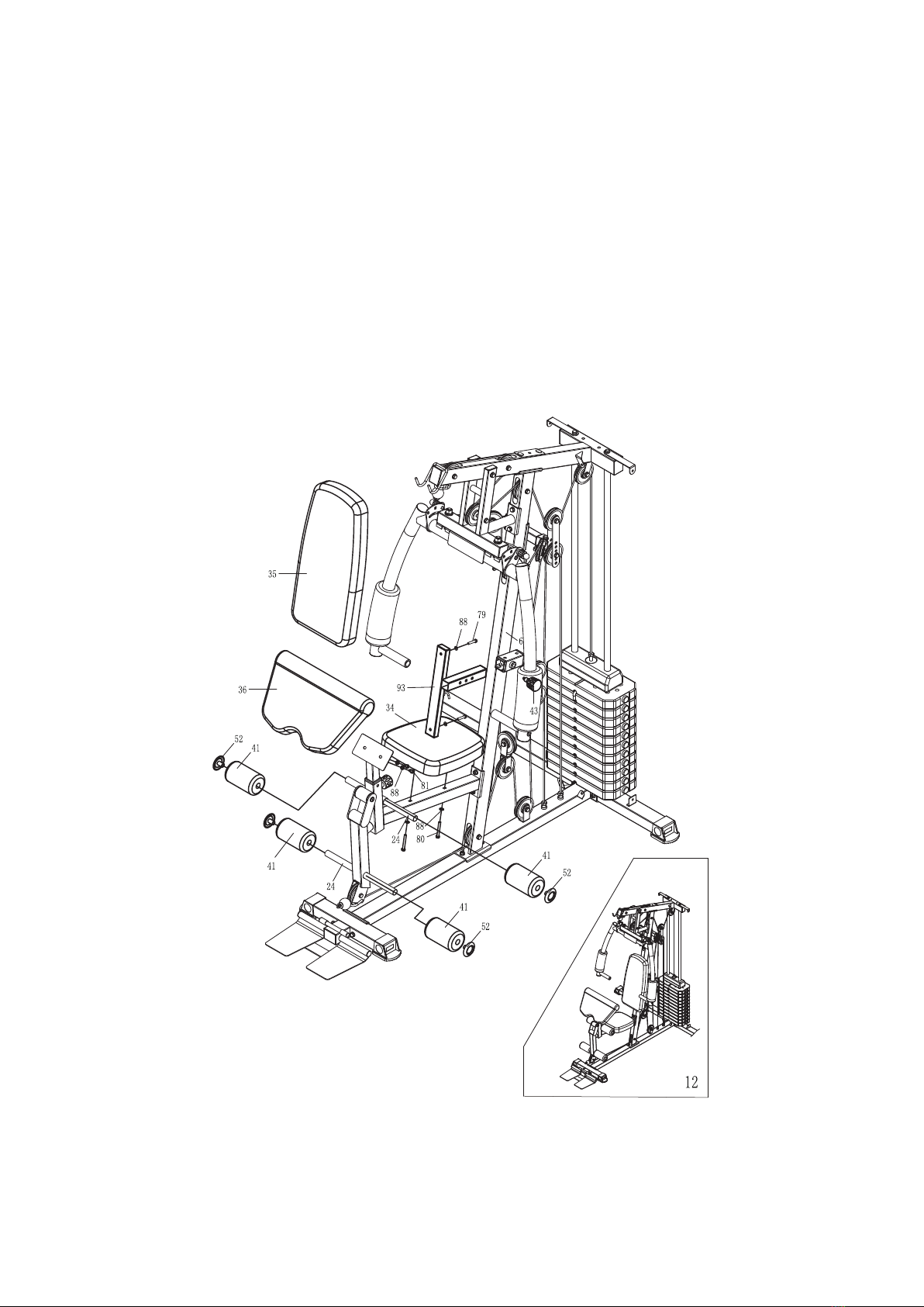
1. Take the back cushion (35) out and fix with the M8*40 hexagon bolt (79) and D8 flat
gasket (88) on the cushion regulating tube (93), insert the back cushion regulating tube (93)
into the front inclined tube assembly (6), and lock and fix it with the elastic pin knob (43);
2. Take the seat cushion (34) out and fix and lock it with M8*65 hexagon bolt (80) and D8
flat gasket (88) according to the figure;
3. Take the hand pad (36) out and fix and lock it with M8*15 hexagon bolt (81) and D8 flat
gasket (88) according to the figure;
4. After installing the 2 sponge stick tubes (24) as shown in the figure, install the D 25
circular tube plug (95) and sponge stick (41) on the sponge stick tubes (24).
17

Step13
1.Place the top tube connecting weldment (96) and top beam assembly (12) according to the
figure;and lock and secure it with M10*90 hexagon bolt (74), D10 flat gasket (87) and M10
locknut (85);
2.Put the iron-net protective cover (25) and the shield junction plate 2 (11) in place according
to the figure, and lock and fix it on the installed body with M10*10 hexagonal socket pan
bolt (78) and D10 flat gasket (87).
18
Table of contents
Other Harison Fitness Equipment manuals


Popular Fitness Equipment manuals by other brands


G-FITNESS
G-FITNESS AIR ROWER user manual

CAPITAL SPORTS
CAPITAL SPORTS Dominate Edition 10028796 manual

Martin System
Martin System TT4FK user guide

CIRCLE FITNESS
CIRCLE FITNESS E7 owner's manual

G-FITNESS
G-FITNESS TZ-6017 user manual

Accelerated Care Plus
Accelerated Care Plus OMNISTIM FX2 CYCLE/WALK user manual


