Harken Industrial 500 User manual

Please read these instructions carefully before installing, servicing, or operating the equipment.
This manual may be modified without notice. In the event of this manual being translated, the English version is definitive. For latest
manual revision go to www.harkenindustrial.com/manuals
PLEASE SAVE THESE INSTRUCTIONS
RIGGERS WINCH 500
Installation Manual – Intended for specialized personnel or expert users
INRW500_A 03/19
Introduction
Safety Precautions 3
Applications/Limitations 4
Specification 5
Installation
Plan Installation 6
Pre-Use Checks 7
Operation
Lifting Loads 8
Lowering Loads 9
Maintenance
Inspection 10
Maintenance 10
Disassembly 11-13
Cleaning 14
Assembly 15-17
Declaration of Conformity 18
Parts
Exploded View 19-20
Parts List 21-22

2 Riggers Winch 500 01/03/19

3 Riggers Winch 500 01/03/19
Safety Precautions
Please read these instructions carefully before operating equipment.
Keep these instructions in a safe place for future reference.
i
This product, as supplied by Harken®, is considered to be applicable to general lifting operations.
Should this product be incorporated into systems for lifting persons, it becomes “partly completed
machinery” and, when appropriate additional safety devices are added, must be certified for its
intended application. Such systems are classified as “machinery for lifting persons” and would
require separate CE marking.
Service Manual
You can download the Service Manual from www.harkenindustrial.com/manuals. This manual is for use only by
specialized personnel. Installation, disassembling and reassembling by personnel who are not experts may cause serious
damage to property or injury to users and those in the vicinity of the product. Harken®accepts no responsibility for
damage or harm caused by not observing the safety requirements and instructions in the service manual. See limited
warranty, general warnings, and instructions at www.harkenindustrial.com/manuals.
Introduction
This manual gives technical information on installation and service. If you do not understand an instruction, contact
Harken®.
WARNING! Strictly follow all instructions to avoid potential hazards that may kill or hurt you and others.
See www.harkenindustrial.com/manuals for general warnings and instructions.
DANGER! This indication alerts you to imminent hazards that will kill or seriously injure you and others
if you don't follow instructions. The message will tell you how to reduce the chance of injury.
WARNING! This indication alerts you to potential hazards that may kill or seriously injure you and others
if you don't follow instructions. The message will tell you how to reduce the chance of injury.
CAUTION! This indication alerts you to potential hazards that may hurt you and others if you do not fol-
low instructions. The message will tell you how to reduce the chance of injury.
4 Riggers Winch 500 01/03/19
Applications/Limitations
WARNING! Subjecting the winch to loads above the maximum working load can cause the winch to
fail or pull off the mounting surface suddenly, possibly resulting in severe injury or death.
B. LIMITATIONS
DO NOT USE:
• With wire rope
• With loads in excess of the maximum working load of 500kg for lifting loads.
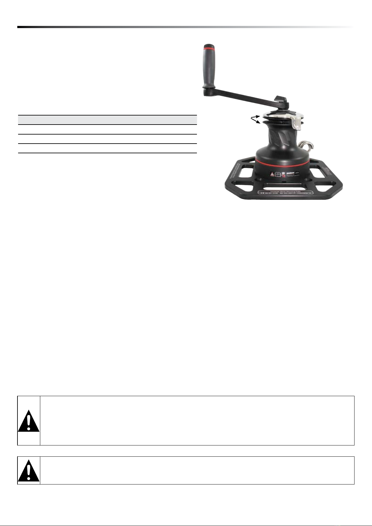
Self-Tailing
Stripper Arm
Handle
Winch
Drum
Self-Tailing
Jaws
Winch
Plate
Pigtail
A. USE
Harken®Riggers Winch 500 is designed to be used as a manually powered, rope-handling winch secured on a
universal mounting plate, for lifting, lowering and pulling loads.
C. TRAINING
This equipment must be installed and used by persons trained in its correct application and use.
D. STANDARDS
This product/system has been certified to EN13157 standards.
E. TESTING
Maximum working loads are 4:1 coefficient ratio of the breaking load.
Part No. Description Quantity
A96889400 Harken Radial Winch 1
F83256700 B10AL Harken Winch Handle (lock-in) 1
A96885400 Plate 1
WARNING! As reported in the Directive 2009/104/EC "Persons may be lifted only by means of work equipement and
accessories provided for that purpose. Without prejudice to Article 5 of Directive 89/391/EC, exceptionally, work equipment
which is not specifically designed for the purpose of lifting persons may be used for that purpose, provided appropriate
action has been taken to ensure safety in accordance with national legislation and/or practice providing for appropriate
supervision" .
CONTENTS SUPPLIED
5 Riggers Winch 500 01/03/19
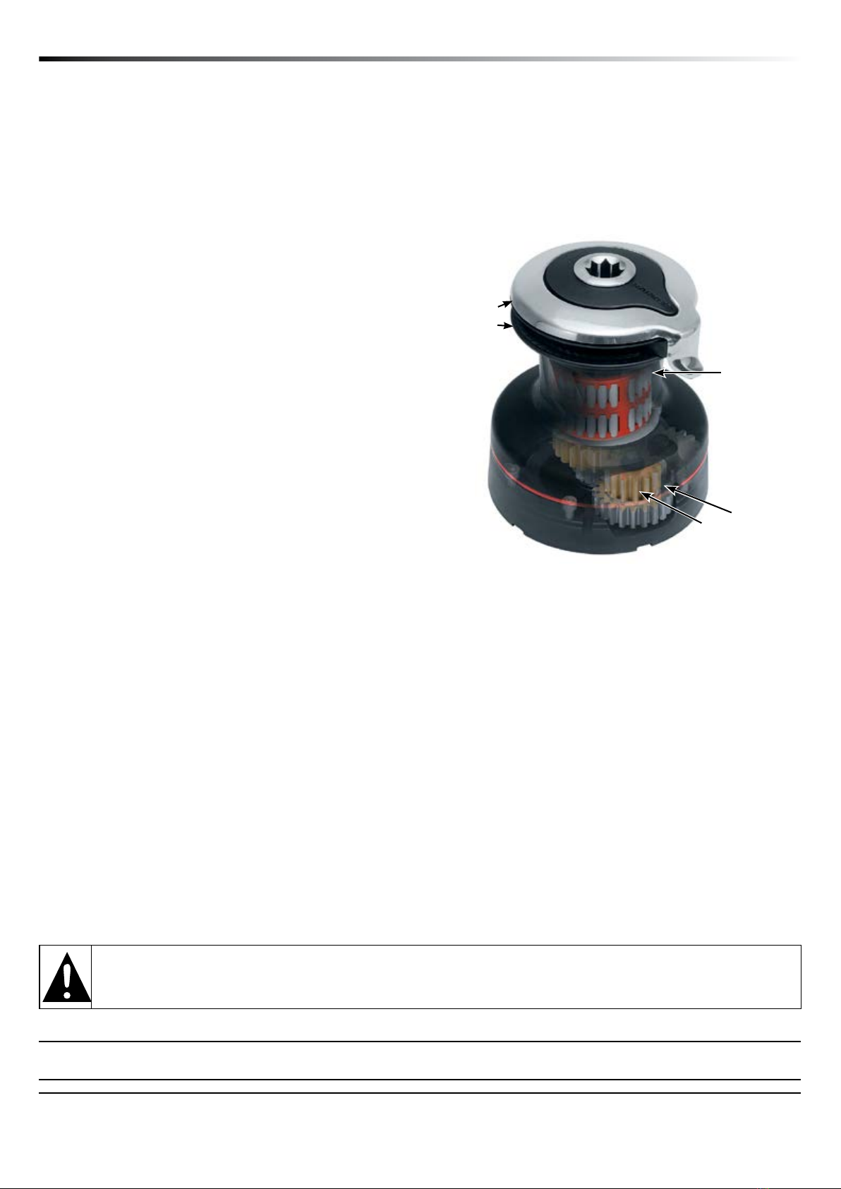
Self-Tailing
Stripper Arm
Hardcoat, PTFE-
Impregnated
Aluminum Drum
and Castle
Bronze and Stainless
Steel Gears
Composite
Bearings
Self-Tailing
Jaws
Part
No.
Ø
Height (H) Weight
Rope entry
height (LE)
Rope Ø
(Min - Max)
Fastener
circle
Fasteners
(HH) Gear ratio Power ratioDrum (D) Base (B)
in mm in mm in mm lb kg in mm in mm in mm mm 1 2 3 1 2 3
INRW500 3
1
/
8
80 6
3
/
16
157 6
7
/
8
175 8.4 3.8 3
1
/
4
82
5
/
16
-
1
/
2
8- 12 4
7
/
8
123 5 x 6 2.13 6.28 —13.50 39.90 —
FEATURES
Maximum Grip – The drum’s gripping surface is designed
specifically to work with the drum diameter and material to
maximize gripping power and reduce rope wear. Diagonal
ribs stop the rope from rising (keeping rope wraps on part
of drum where you have the best control), prevent
overrides, and provide a smooth controlled release as rope
exits the winch.
Spring-loaded, self-tailing jaws adjust under rope pressure
to accept a variety of rope diameters. Teeth grip evenly
with or without load.
Lightweight – overall weight only 7kg
Powerful – 2-speed gearing allows optimum use of
manpower to deliver power and speed.
Reliable & Easy to Maintain – Composite roller
bearings and bushings don’t require lubrication and have excellent corrosion resistance. This ‘metal-
replacement’ material is completely non-reactive to saltwater and most chemicals, and has very good wear
and abrasion resistance under maximum operating loads.
Load-carrying gears and pins are 17-4PH stainless steel for strength and durability.
Planetary gears are bronze to avoid stainless-on-stainless galling.
Winches can be disassembled and serviced where mounted.
Easy Line Control - Locking jaws hold loaded rope securely during operation and while suspended. The
stripper arm is shaped to smoothly feed the rope in and out of the jaws so the operator can use both hands
to turn the winch. The stripper arm adjusts to multiple positions after the winch is mounted so rope exit
position can be optimized.
SPECIFICATIONS
Maximum Working Load:
Winch: 500 kg
Break Load: 2800 kg
DESCRIPTION
Lightweight CE certified portable winch, mounted on an adaptor place.
The winch can be utilized in many applications; from utility masts, telecoms, marine, wind-turbine transition piece,
davits, stage and theatre rigging.
The adaptor plate can be affixed in a number of ways, dependant on the environment and industry; from ratchet
straps, M10 bolts, karabiners, to scaffold clamps. This makes for a truly universal and adaptable lifting solution.
Specifications
WARNING! Subjecting the winch to loads above the maximum working load can cause the winch to
fail or pull off the mounting plate suddenly, possibly resulting in severe injury or death.
Other manuals for 500
1
Table of contents
Other Harken Industrial Winch manuals


Popular Winch manuals by other brands


Comeup
Comeup DV-9 manual

Orvea
Orvea Italwinch 805 Installation and user manual

Prowinch
Prowinch PWJTHF300 user manual

Clas Ohlson
Clas Ohlson LD2000-A manual

Runva
Runva EWD8000 Assembly & operating instructions

Ingersoll-Rand
Ingersoll-Rand LIFTSTAR FG 1500/CN Series Parts, operation and maintenance manual