Harman Accentra 52i Wood Fireplace ZC Kit User manual

13-89-574205_R4 • 07/19
Accentra 52i Wood Fireplace ZC Kit
Instructions - Part #1-00-574205
Installation into a Zero Clearance Wood Fireplace
Contents:
(1) HWH TEK 10 x 3/4 - 3-30-511007517
(1) Modication label - 1601246
When installing the Accentra 52i into a factory built wood
burning fireplace, several things need to be taken into
consideration.
The size of the replace opening. Will the unit t into the
opening? Some of the factory built replaces have metal
smoke shields inside the top that can be removed to gain
height. Keep in mind that anything removed from the factory
built replace must be attached to the replace with a metal
wire. Floor protection guidelines, as listed previously, must
also be followed.
The manufactured replace may not be altered beyond the
exceptions listed below. Never remove masonry bricks or
mortar from an existing replace.
The following modications are permissible:
• Removal of the damper or lock in open position
• Removal of smoke shelf or bafe
• Removal of andirons or ember catchers
• Removal of log grate
• Removal of view screen or curtain
• Removal of doors
• External trim pieces, that do not affect the operation of
the replace, may be removed providing they can be
stored on or within the replace for reassembly if the
insert is removed.
• If the hearth extension is lower than the replace opening,
the portion of the insert extending onto the hearth must
be supported.
• Final approval of this type of installation is contingent
upon the authority having jurisdiction.
• If any of the modications detailed above are completed
on the replace during installation, the label included in
this kit, part number 1601246 must be installed.
The factory built chimney must be listed per UL 127 (US)
and meet type HT requirements of UL 103 (US). Factory
Built replace chimneys tested to UL 127-98 may be, at the
replace manufacturers option, tested to the same criteria
as UL 103HT requirements. If the chimney is not listed as
meeting HT requirements, or if the factory built replace was
tested prior to 1998, a full height listed chimney liner must be
installed from the appliance ue collar to the chimney top.
Liner must meet high temperature (2100° F) per UL1777
(US). The liner must be securely attached to both the ue
collar and the chimney cap. To prevent room air passage to
the chimney cavity of the replace, seal the damper area
around the chimney liner with berglass batting.
* Floor protection must be used from hearth opening to 6” (152mm)
in front of door glass and 6” (152mm) to each side of the stove body
OR 8” (203mm) to sides and 18” (457mm) in front (CANADA) to
protect combustibles from hot ashes. A minimum size will be 16.5”
deep by 30” wide and be made of a non-combustible material or
meet UL approval.
A = to sidewall
B = to 12" mantel
C = to 3/4" trim
D = to 3/4" trim
E = oor protection
12” (305mm) Mantel
B
A
EE
C
D
Clearances: A B *C *D E (From Glass)
From Insert
Body:
12”
(305mm)
12”
(305mm) 0” 0” 6”
(152mm)
*3/4” trim, zero clearance to cast surround 18”
(457mm Canada)
23-89-574205_R4 • 07/19
The new nished height of the replace oor should be level
with the hearth. If the replace oor is too low, the installer
can only use non-combustible materials to raise the stove
mounting frame. Any shimming needs to be positioned
beneath the frame leveling bolt areas.
Attach the wings along with ue tailpipe and gasket
(and outside air, if used) onto insert mounting frame and
temporarily install into opening. Lay the ash lip onto the
frame rails to conrm proper hearth height. If the ash lip
to hearth clearance needs set or Insert frame needs
leveled, install leveling bolts into frame oor and correct as
necessary.
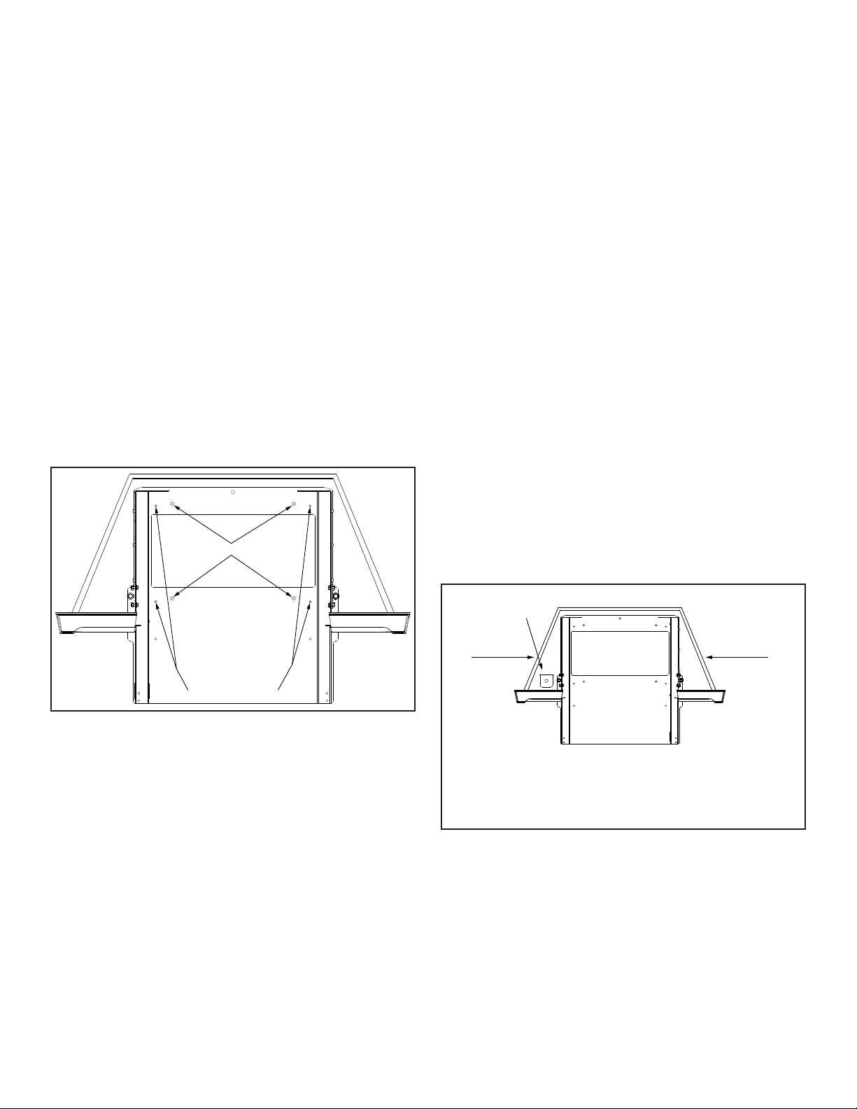
When mounting is correct, the insert mounting frame should
be secured through the oor by using lag bolts or screws.
Figure 1 Remove the ash lip and connect the ue, (along
with outside air pipe, if used) to their tailpipes. Type PL vent,
type L vent, and ex pipe approved for pellet stoves are
allowed for this installation. Flex pipe may only be used on
the ue if running vertically.
The ue pipe may stop one foot inside the existing chimney
and be sealed with non-combustible materials. It is preferred
that the ue runs to the top of the existing chimney to help
avoid possible performance issues.
Levelling Bolts
Frame Mounting Bolts
Figure 1
Alternate venting method and outside air connection
The Harman direct vent wall pass thru may be used to vent
the Accentra 52i directly outside if the zero clearance unit
is located on an exterior wall. Installation will require using
zero clearance kit #1-00-574205 along with the direct vent
wall pass thru kit (1-00-677177) and the 3” stub pipe kit (1-
00-674039) for 3” pellet pipe.
The Insert will need an outside air kit (1-00-574350) installed
to nish the connection.
The thickness from the rebox inner wall to the surface of the
exterior wall may not be under 4-1/2” or go above 10-5/8”.
This is the range the direct vent wall pass thru is designed
to t. Flexible ue pipe may not be used with the direct vent
wall pass thru. Only PL vent with 3” or less clearance rating
is allowed.
The existing chimney on the zero clearance cabinet must
be sealed if using the direct vent wall pass thru.
Connecting only outside air through rear of cabinet
The exhaust venting may be run through the existing ue
with the outside air being routed through the back wall of the
zero clearance cabinet. The air pipe must be sealed where
it passes through the cabinet and the outer wall. A exible
pipe suitable for the connection is available through your
Harman dealer.
An inlet cover for the pipe is required to keep birds, rodents,
etc. out of the airway. This is available from your Harman
dealer (1-10-09542).
The Insert will need an outside air kit (1-00-574350) installed
to nish the connection.
When installing an electrical box inside the cabinet, it may
be done on the left front corner only, beside the Insert
mounting frame and near the opening of the zero clearance
cabinet. Figure 2.
The installer can only use a metal handy box with a metal
receptacle cover. The power line must be installed according
to any local electrical codes where piercing through cabinet
walls is required. The power line shall enter the left side
within 6” of the opening and the cabinet oor and go into
the handy box. It can also run from the right side of the
cabinet within 6” of the opening and the cabinet oor. It must
be ty-wrapped and routed over the top of the Insert frame,
following the original Insert cord mounting. The power line
and the Insert cord may not be run around the back of the
Zero Clearance cabinet or Insert mounting frame. The stove
cord must be ty-wrapped and secured near the handy box.
Be sure to follow all local electrical codes.
Handy box
Location
Powerline entrance
area within 6” of
opening
Powerline entrance
area within 6” of
opening
Receptical faces rear of cabinet.
Powerline must follow any codes when piercing through cabinet wall(s) and at
handy box.
Powerline and stove cord must be protected from sharp edges and may not run
behind stove.
Figure 2
This manual suits for next models
1
Other Harman Fireplace Accessories manuals

Popular Fireplace Accessories manuals by other brands


Bronpi
Bronpi KIT-1 instructions

Town & Country Fireplaces
Town & Country Fireplaces 22150051 instructions

Travis Industries
Travis Industries 33 DVI installation instructions

Superior
Superior ASD3628-TI installation instructions

pleasant hearth
pleasant hearth OFP28WG operating manual

IHP
IHP Astria Series manual

Firegear
Firegear FG-H-2110SS Installation and operating instructions

Nibe
Nibe Contura C i31 Installation instruction

kozy heat
kozy heat KZK-052 manual

SimpliFire
SimpliFire SF-WM36 Service manual

Bluegrass Living
Bluegrass Living BC18NR OWNER'S OPERATION AND INSTALLATION MANUAL

pleasant hearth
pleasant hearth IRIS SCROLL quick start guide