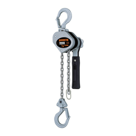
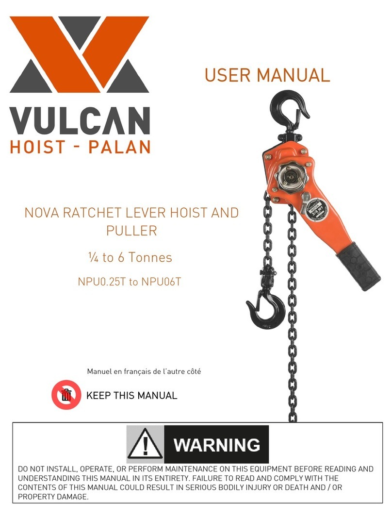
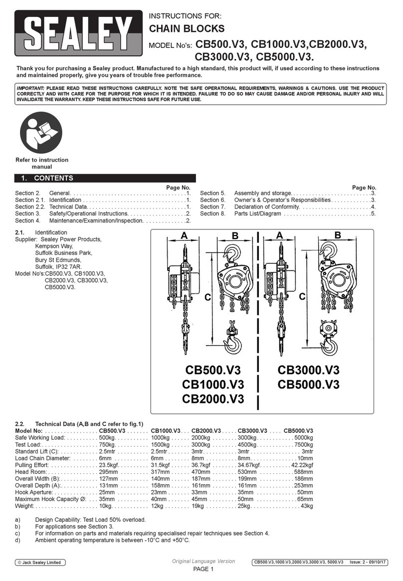
Harrington TCS Series User manual

CHEETAH
AIR POWERED
CHAINHOIST
TCSSERIES
¼ Ton, ½ Ton and 1 Ton Capacity
Code, Lot and Serial Number
EFFECTIVE: May 1, 2006
This equipment should not be installed, operated or
maintained by any person who has not read and understood
all the contents of this manual. Failure to read and comply
with the contents of this manual can result in serious bodily
injury or death, and/or property damage.
EFFECTIVE: September 18, 2018

2
Table of Contents
Section Page Number
1.0 Important Information and Warnings…………………………………………………………………4
1.1 Terms and Summary
1.2 Warning Tags and Labels
2.0 Technical Information………………………………………………………………………………… 8
2.1 Specifications
2.2 Dimensions
2.3 Part Names
3.0 Pre-operational Procedures………………………………………………………………………....13
3.1 Air Supply System Requirements
3.2 Air Supply Capacity AndRegulation
3.3 Lubrication
3.4 Filtration
3.5 Air Dryer
3.6 Piping, Hoses And Fittings
3.7 Mounting Location
3.8 Connecting Hoist to Air Supply
3.9 Mounting the Hoist
3.10 Optional Chain Container
3.11 Non-Stationary Application
3.12 Preoperational Checks and Trial Operation
4.0 Operation……………………………………………………………………………………………. 21
4.1 Introduction
4.2 Shall’s and Shall Not’s for Operation
4.3 Hoist Controls
4.4 Adjusting the Controls
4.5 Speed Adjustment Controls
4.6 Pendant Controllability Adjustment

3
Section Page Number
5.0 Inspection………………………………………………………………………….…………………27
5.1 General
5.2 Inspection Classification
5.3 Frequent Inspection
5.4 Periodic Inspection
5.5 Occasionally Used Hoists
5.6 Inspection Records
5.7 Inspection Methods and Criteria
6.0 Lubrication…………………………………………………………………………………………... 34
6.1 Air Hoist Lubrication
6.2 Load Chain Lubrication
6.3 Hooks and Suspension Components
7.0 Maintenance & Handling……………………………………………………………………………36
7.1 Brake
7.2 Load Chain
7.3 Pendant
7.4 Load Sheave Inspection
7.5 Storage
7.6 Outdoor Installation
8.0 Troubleshooting…………………………………………………………………………………….. 42
9.0 Warranty…………………………………………………………………………………………….. 44
10.0 Parts Information…………………………………………………………………………………….45

4
1.0 Important Information and Warnings
1.1 Terms and Summary
This manual provides important information for personnel involved with the installation, operation and maintenance
of this product. Although you may be familiar with this or similar equipment, it is stronglyrecommended that you read
this manual before installing, operating or maintaining the product.
Danger, Warning, Caution and Notice - Throughout this manualthere are steps and procedures that can present
hazardous situations. The following signal words are used to identify the degree or level of hazard seriousness.
Danger indicates animminentlyhazardous situation which, if not avoided, will result in death or
serious injury, and property damage.
Warning indicates an imminentlyhazardous situation which, if not avoided, could result in death or
serious injury, and property damage.
Caution indicates a potentially hazardous situation which, if notavoided, may result minor or
moderate injury or property damage.
Notice is used to notifypeople of installation, operation, or maintenance information which is
important but not directly hazard-related.
These general instructions deal with the normal installation, operation, and maintenance situations encountered with
the equipment described herein. The instructions should not be interpreted to anticipate everypossible contingency
or to anticipate the final system, crane, or configuration that uses this equipment. For systems using the equipment
covered by this manual, the supplier and owner of the system are responsible for the system’s compliance with all
applicable industrystandards, and with all applicable federal, state and local regulations/codes.
This manual includes instructions and parts informationfor avariety of hoisttypes. Therefore, all instructions and
parts information maynot applyto any one type or size of specific hoist. Disregard those portions of the instructions
that do not apply.
Record your hoist’s Code and Serial Number (see Section 3.12.6 and Figure 10-1) on the front cover of this manual
for identification and future reference to avoid referring to the wrong manual for information or instructions on
installation, operation, inspection, maintenance, or parts.
Use only Harrington authorized replacement parts in the service and maintenance of this hoist.

5
Equipment described herein is not designed for and MUST NOT be used for lifting, supporting, or transporting people,
or for lifting or supporting loads over people.
Equipment described herein should not be used in conjunction with other equipment unless necessary and/or
required safety devices applicable to the system, crane, or application are installed bythe system designer, system
manufacturer, crane manufacturer, installer, or user.
Modifications to upgrade, rerate, or otherwise alter this equipment shall be authorized only by the original equipment
manufacturer.
Equipment described herein maybe used in the design and manufacture of cranes or monorails. Additional
equipment or devices maybe required for the crane and monorailto comply with applicable crane design and safety
standards. The crane designer, crane manufacturer, or user is responsible to furnish these additional items for
compliance. Refer to ANSI/ASME B30.17, “Safety Standard for Top-Running Single Girder Cranes”; ANSI/ASME
B30.2 “Safety Standard for Top-Running Double-Girder Cranes”; and ANSI/ASME B30.11 “Safety Standard for
Underhung Cranes and Monorails”.
If a below-the-hook lifting device or sling is used with a hoist, refer to ANSI/ASME B30.9, “Safety Standard for
Slings” or ANSI/ASME B30.20, “Safety Standard for Below-the-Hook Lifting Devices”.
Hoists, trolleys and cranes, used to handle hot molten material mayrequire additional equipment or devices. Refer to
ASTM-E-2349, “Standard for Safety Requirements in Metal Casting: Sand Preparation, Molding, and Core Making;
Melting and Pouring; and Cleaning and Finishing”.
Failure to read and comply with anyone of the limitations noted herein can result in serious bodily injuryor death,
and/or property damage.

6
HAZARDOUS AIR PRESSURE IS PRESENT IN THE HOIST, IN THE SUPPLY OF COMPRESSED AIR TO THE
HOIST, AND IN THE CONNECTIONS BETWEEN COMPONENTS.
Before performing ANYmaintenance on the equipment, de-energize the supply of compressed air to the
equipment, and lock and tag the supply device in the de-energized position. Refer to ANSI Z244.1, “Personnel
Protection - Lockout/Tagout of Energy Sources.”
Only trained and competent personnel should inspect and repair this equipment.
It is the responsibilityof theowner/user toinstall, inspect, test, maintain, and operate a hoist in accordance with
ANSI/ASME B30.16, “Safety Standard for Overhead Hoists”, OSHA Regulations. If the hoist is installed as part of a
total lifting system, such as an overhead crane or monorail, it is also the responsibility of the owner/user to comply with
the applicable ANSI/ASME B30 volumethat addresses that type of equipment.
It is the responsibilityof the owner/user to have all personnel that will install, inspect, test, maintain, and operate a
hoist read the contents of this manual and applicable portions of ANSI/ASME B30.16, “Safety Standard for Overhead
Hoists” and OSHA Regulations. If the hoist is installed as part of a total lifting system, such as an overhead crane, the
applicable ANSI/ASMEB30 volume that addresses that type of equipment must also be read byall personnel.
If the hoist owner/user requires additional information, or if any information in the manual is not clear, contact
Harrington or the distributor of the hoist. Do not install, inspect, test, maintain, or operate this hoist unless this
information is fully understood.
A regular schedule of inspection of the hoist in accordance with the requirements of ANSI/ASME B30.16 should be
established and records maintained.

7
1.2 Warning Tags and Labels
The warningtag illustrated below inFigure 1-1 is supplied with each hoist shipped from the factory. If the tag is not
attached to your hoist (for pendant control, the warning tag is attached to the pendant hose; for the pull cord control, the
warning tag is attached to the up cord), order a tag from your dealer and install it. See parts list in the parts section of
this manual. Read and obey all warnings attached to this hoist. Tag is not shown actual size.
Bilingual Version
Figure 1-1 Warning Tag Attached to Hoist

8
2.0 Technical Information
2.1 Specifications
2.1.1 Product Code
2.1.2 Operating Conditions and Environment
Temperature range:
+14° to +140°F (-10° to +60°C)
Relative Humidity:
85% or less
Noise Level:
83 dba maximum @ 1 meter when lifting rated load
93 dba maximum @ 1 meter when lowering rated load
Supply Air:
60 to 90 psi (0.4 to 0.6 MPa)
Air Consumption:
60 to 75 cfm (1.7 to 2.1 m³/min)
Air Lubrication Requirements:
Minimum 10 to 15 drops per minute (0.2-0.3 cc/min) of oil
Air Filtration Requirements:
Maximum 5 micron air filter or finer

9
Table 2-1 Hoist Specifications
Cap.
(Tons)
Product
Code
Standard
Lift
(ft)
Push
Button
Hose
L
(ft)
Up/Down Speeds
(ft/min @ 90 psi)
Up/Down
Air Consumption Rates
(cubic ft/min @ 90 psi)
Load Chain
Diameter
(mm)
x
Chain Fall
Lines
Net
Weight
(lbs)
Weight for
Additional
One foot
of Lift
(lbs)
No Load
w/Full Load
No Load
w/Full Load
Pendant Model
1/4
TCS250P
10
8.1
207/125
121/197
78/67
64/74
6.3 X 1
42
0.6
1/2
TCS500P
8.1
108/62
60/108
74/64
60/71
6.3 X 1
42
0.6
1
TCS1000P2
8.1
54/31
30/54
74/64
60/71
6.3 x 2
55
1.2
Cord Model
1/4
TCS250C
10
7.3
207/125
121/197
78/67
64/74
6.3 X 1
40
0.6
1/2
TCS500C
7.3
108/62
60/108
74/64
60/71
6.3 X 1
40
0.6
1
TCS1000C2
7.3
54/31
30/54
74/64
60/71
6.3 x 2
53
1.2

10
2.2 Dimensions
Table 2-2 TCS with Pendant Control Dimensions
Single Fall Hoist
Double Fall Hoist
Cap.
(Tons)
Product
Code
Headroom
C
(in)
a
(in)
b
(in)
d
(in)
e
(in)
g
(in)
h
(in)
i
(in)
j
(in)
1/4
TCS250P
16.3
14.4
6.6
6.3
7.6
1.0
4.4
2.2
1.0
1/2
TCS500P
16.3
14.4
6.6
6.3
7.6
1.0
4.4
2.2
1.0
1
TCS1000P2
17.9
14.4
9.0
6.3
8.0
1.1
6.3
2.8
1.9

11
Table 2-3 TCS with Cord Control Dimensions
Single Fall Hoist
Double Fall Hoist
Cap.
(Tons)
Product
Code
Headroom
C
(in)
a
(in)
b
(in)
d
(in)
e
(in)
g
(in)
h
in)
i
(in)
j
(in)
1/4
TCS250C
16.3
14.4
8.7
6.3
7.6
1.0
5.3
3.3
1.0
1/2
TCS500C
16.3
14.4
8.7
6.3
7.6
1.0
5.3
3.3
1.0
1
TCS1000C2
17.9
14.4
9.0
6.3
8.0
1.1
6.3
2.8
1.9
Table 2-4 Top and Bottom Hook Dimension*
Units = inch
Product Code
a
b
c
d
e
f
g
h
TCS250C/P
0.6
0.8
0.6
0.8
1.4
1.3
1.0
2.9
TCS500C/P
0.6
0.8
0.6
0.8
1.4
1.3
1.0
2.9
TCS1000C2/P2
1.4
0.9
1.1
0.9
1.6
1.6
1.1
4.2
*Refer to Section 5.7 for inspection dimensions and limits.

12
2.3 Part Names
Figure 2-1 Hoist Part Identification Diagrams –TCS250C/P and TCS500C/P
Figure 2-2 Hoist Part Identification Diagrams –TCS1000C2/P2

13
3.0 Preoperational Procedures
3.1 Air Supply System Requirements
3.1.1
Pressure and Flow - Verify that the air supply system has capacityto supply your
air hoist with required pressure and flow. Otherwise the hoist mayoperate poorly or may fail to
operate. See Section 3.2.
3.1.2
Lubrication - The hoist requires lubrication for proper operation. The oil in the air
supplyis the primarysource of lubrication to the hoist. Therefore, a dedicated air supply lubricator must
be used with the hoist. Refer to Section 3.3.
3.1.3
Air Quality- Good air quality is essential toprevent damage to your hoist and to
ensure its proper operation. The air must be clean and free of debris such as dirt and rust. Refer to
Section 3.4 for filtration requirements. The airmust also be dry; free of moisture and water. Refer to
Section 3.5.
3.2 Air Supply Capacity And Regulation
3.2.1 Capacity - The air supplysystem must be capable of delivering the required airflow (cfm) to the hoist
inlet port. Without the required airflow the hoist will not operate properly or maynot operate at all. See
Section 2.0 for your hoists air consumption requirements. In determining if your system is capable of
supplying the required airflow, consider the following:
Capacity of compressor(s) and tank
Other air consuming equipment
Flow restrictions such as pipes, hoses, valves and fittings
Inadequate capacity will cause a significant drop in pressure when the hoist is operated, and could
cause poor performance or failure to operate.
3.2.2 Regulation - The hoist requires a constant supply of air at a pressure of between 60 and 90 psi. If the
air supply is not regulated or is regulated at a pressure greater than 90 psi, then a regulator must be
used. The regulator maybe located anywhere upline of the lubricator in the air supply to the hoist.
3.3 Lubrication
3.3.1
The hoist must be supplied with its own lubricator. The lubricator must be located
as follows:
1) Best location - At the hoist inlet. In this case the lubricator canbe either the mist type or drop
type.
2) Second best location - No more than 15 feet away from the hoist, at the same elevation or above
the hoist inlet. In this case the mist type lubricator must be used.
3) Third best location - No more than 15 feet away belowthe hoist. In this case the mist type
lubricator must be used.
3.3.2
The lubricator must be set to deliver the equivalent of 10 to 15 drops of oil per
minute (0.2-0.3 cc/minute). The hoist’s exhaust will emit a fine oil mist when properly lubricated.

14
3.4 Filtration
3.4.1
The air entering the hoist inlet must not contain any particulate greater than 5
microns in size. Therefore, the hoist must have a 5 micron filter in its air supply. The filter must be
upstream of the lubricator.
3.4.2 The filter servicing the hoist can also service other hoists and air consuming equipment. In this case,
the air filter must be in sized for the total air consumption of the equipment it is servicing.
3.5 Air Dryer -
To prevent corrosion and hoist malfunction, employ an air dryer in the air
supplysystem to ensure that dry air is supplied to the hoist. If there ismoisture in the air supplied to the hoist,
this moisture will cause corrosion on internal hoist components during periods when the hoist is idle leading to
hoist malfunction.
3.6 Piping, Hoses And Fittings
3.6.1
System Configuration - The system should be configured as shown in Figure 3-1.
Since moisture tends to accumulate in compressed air systems, corrosion mayresult if the system is
not periodicallydrained.
Arrange for a drain in the air supply piping at the lowest point in the piping, and
Periodically drain the system to removemoisture/water from the system and to prevent corrosion.
Filter, regulator (if equipped), and lubricator must be arranged in the order shown in Figure 3-2.
Figure 3-1 Diagram of Air SupplyConfiguration (Typical)
Figure 3-2 Typical Air Supply Filter, Regulator, and Lubricator.

15
3.6.2
Piping - Pipe should be sized to accommodate the hoist airflow requirements.
Table 3-1 gives recommended pipe sizes.
Table 3-1 Air Supply Pipe and Hose Sizes
Model
Diameter of Supply Pipe
Diameter of Supply Hose
TCS250C/P
TCS500C/P
TCS1000C2/P2
Inside diameter
3/4” or larger
Inside diameter
1/2” or larger
3.6.3
Hoses - The connection from the air supplysystem piping to the hoist must be
made with a flexible pressure hose. Due to normal line losses in air supply lines:
Do not use hose smaller than specified in Table 3-1, and
Limit the length of the hose to that specified in Figure 3-3.
If your application exceeds these requirements consult factory.
Figure 3-3 Typical Arrangements of Filter,Regulator and Lubricator and
Maximum Air Supply Hose Lengths
3.6.4
Fittings - Importantconsiderations regardingfittings inthe hoist's air supply
include:
When connecting air supplycomponents, remove all dirt or debris from the connecting surfaces of
the hoses, pipes, fittings, or threaded fasteners to prevent contaminants from entering the hoist.
Keep airflowrestrictions such as quick disconnect fittings, bends, elbows, and adapters to a
minimum.
3.6.5
Before connecting the hoist to its air supply line; perform the proper draining and
purging procedures to prevent contaminants or moisture from entering the hoist.

16
3.7 Mounting Location
3.7.1
Prior to mounting the hoist ensure that the suspension and it supporting structure
are adequate to support the hoist and its loads. If necessaryconsult a professional that is qualified to
evaluate the adequacyof the suspension location and its supporting structure.
3.7.2
See Section 7.6 for outdoor installation considerations.
3.8 Connecting Hoist to Air Supply
3.8.1
HAZARDOUS AIR PRESSURE IS PRESENT IN THE HOIST, IN THE SUPPLY
OF COMPRESSED AIR TO THE HOIST, AND IN THE CONNECTIONS BETWEEN COMPONENTS.
3.8.2 Shut off the air supply and stop the airflow completely. Lock out and tag out in accordance with ANSI
Z244.1 “Personnel Protection -Lockout/Tagout of Energy Sources”.
Figure 3-4 Air SupplyConnection to Hoist –Cord or Pendant Models
3.8.3
Before connecting the air supply hose to the hoist, always purge the air hose to
clear any debris and water.
3.8.4 Applyapproximately10-15 drops of turbine oil (see approved lubricant under Section 6.0 Lubricants)
into the hose before attaching to the hoist.
3.8.5 Make connections to air supply; reference Figure 3-4.Use a reducing adapter at the hoist valve
section for hose sizes larger than 1/2”.
3.8.6
Where conditions dictate, the installation sequence can be reversed by mounting
the hoist first (Section 3.9) followed be connecting the air supply.
3.9 Mounting the Hoist
3.9.1 Manual Trolley - Follow instructions in Owner’s Manual provided with the trolley.
3.9.2 Hook Mounted to a Fixed Location - Attach the hoist’s top hook to the fixed suspension point.
3.9.3
Ensure that the fixed suspension point rests on the center of the hook’s saddle and
that the hook’s latch is engaged.

17
3.10 Optional Chain Container
3.10.1 Follow instructions below to install the optional chain container. Refer to Figure 3-5.
1) Attach the metal bracket on top of the chain container to the lower boss on the side of the hoist body
using the M8 Socket Bolt, Washers, Nut and Split Pin provided.
2) Attach the support chain to the upper boss on the side of the hoist bodyusing the M6 Socket Bolt,
Washers, Nut and Split Pin provided.
3) Make sure all fasteners on the chain container and chain attachment points are secure and that the
split pins are sufficiently bent.
4) Feed the Chain into the Chain Container beginning with the no-load end. Take care to avoid twisting or
tangling the Chain.
5)
Do not use the Chain Container if anyparts are damaged or if any
fasteners/hardware are missing.
Figure 3-5 Chain Container Installation
3.11 Non-Stationary Application
3.11.1 For applications such as rental fleets or construction sites where the hoist is moved from place-to-
place, a filter and lubricator are stillrequired. Consult factoryfor recommendedmethods.
3.11.2 Connections and fittings must be kept clean and care taken to prevent dirt, debris and moisturefrom
entering the hoist.
3.11.3 Recommended practice for removing the hoist from an installation:
1) Run the hoist briefly with well lubricated air
2) Shut off the air supply to the hoist, bleed off anypressure in the system then disconnect the air supply
line.
3) Inject a small quantity(approximately20 drops) of turbine oil (see Section 6.0) into the hoist’s inlet port
4) Plug the inletport

18
3.12 Preoperational Checks and Trial Operation
3.12.1
Check for the availability of required operating air pressure of between 60 psi to
90 psi at the hoist's inlet port before trying to operate the hoist.
3.12.2
Verifythat the load chain is not twisted or tangled and that the bottom hook is not
capsized prior to operating the hoist. Correct all chain irregularities before conducting the first hoist
operation. See Figures 3-6 and 3-7.
Figure 3-6 Twist in Load Chain
Figure 3-7 Capsized Hook and Chain
3.12.3
Confirm the adequacyof the rated capacityfor all slings, chains, wire ropes and all
other lifting attachments before use. Inspect all load suspension members for damage prior to use and
replaceor repair all damaged parts.

19
3.12.4
Verifythat the Chain/Limit Lever is operational and can move freelyin both the up
and down directions. For reference see Figure 3-8.
Figure 3-8 Limit Switch Components –
TCS250C/P, TCS500C/P and TCS1000C2/P2
3.12.5 Measure and record the “K” dimension of all hooks on hoist. See Table 5-6 under Section 5,
“Inspection”. Always use the same side of the hook to measure and record the "K" dimension.
3.12.6 Record the hoist Code Number and Serial Number (from the nameplate on the hoist –see Section 10)
in the space provided on the cover of this manual.
3.12.7 Ensure that the hoist is properlyinstalled to either a fixed point, or trolley, whichever applies.
3.12.8 If hoist is installed on a trolley, ensure that
trolleyis properlyinstalled on the beam, and
stops for the trolley are correctlypositioned and securely installed on the beam.
3.12.9 Ensure that all nuts, bolts and split (cotter) pins are sufficientlyfastened.
3.12.10 For hoists with pendant controls, ensure that the Pendant Hoses and Strain Relief wire are properly
attached to the hoist. See Section 7.4.
3.12.11
Check Air Supply- Check air supply before everyday use. Ensure proper air
quality and air pressure.
3.12.12
Check the lubricator for proper function and adequate oil level.

20
3.12.13 Confirm proper operation.
Before operating read and become familiar with Section 4 - Operation.
Before operating ensure that the hoist (and trolley) meets the Inspection, Testing and Maintenance
requirements of ANSI/ASME B30.16.
Before operating ensure that nothing will interfere with the full range of the hoist’s (and trolley’s)
operation.
3.12.4 Proceed with trial operation to confirm proper operation.
Make sure hook travel is in the same direction as shown on controls.
Initially operate slowly under no load in both directions. Verifycontrols agree with hoist direction.
Perform inspections per Section 5.3, “Frequent Inspections”.
This manual suits for next models
6
Table of contents
Other Harrington Chain Hoist manuals
Popular Chain Hoist manuals by other brands
KITO
KITO ED Series Owner's manual and safety instructions

Steinberg
Steinberg SBS-EH-600/18 user manual
HADEF
HADEF 11/09 Installation, operating and maintenance instructions
Liftket
Liftket STAGEKET operating instructions

Coffing Hoists
Coffing Hoists ESC-680-1 Operating & maintenance instructions
Comeup
Comeup DH-300A quick start guide
