Harrington HS-3644 User manual

Harrington Signal
HS-3644
Annunciator
Installation Manual
Revision1
Document # LT-2017HAR
HARRINGTON
FIRE ALARM
SIGNAL INC.


Copyrights and Trademarks
This manual is copyright 1994 - 2005 by Harrington Signal Inc.
No part of this publication may be reproduced, transmitted, transcribed, stored in a
retrieval system, or translated into any language or computer language, in any form by
any means electronic, magnetic, optical, chemical, manual, or otherwise without the prior
consent of Harrington Inc.
Harrington Signal, Inc.
2519 4th Ave.
Moline, Illinois 51265

Cautions and Warnings
READ AND SAVE THESE INSTRUCTIONS. Follow the instructions in this
installation manual. These instructions must be followed to avoid damage to this
product and associated equipment. Product operation and reliability depends upon
proper installation.
DO NOT INSTALL ANY PRODUCT THAT APPEARS DAMAGED. Upon unpacking
your equipment, inspect the contents of the carton for shipping damage. If damage
is apparent, immediately file a claim with the carrier.
ELECTRICAL HAZARD - Disconnect electrical field power when making any
internal adjustments or repairs. Servicing should be performed by qualified
personnel.
STATIC HAZARD - Static electricity can damage components. Therefore, handle as
follows:
• Ground yourself before opening or installing components
• Prior to installation, keep components wrapped in anti-static material at all
times.
RADIO FREQUENCY ENERGY - This equipment generates, uses, and can radiate
radio frequency energy and if not installed and used in accordance with the
instruction manual, may cause interference to radio communications. It has been
tested and found to comply with the limits for a Class A computing device pursuant
to Subpart J of Part 15 of FCC Rules, which are designed to provide reasonable
protection against such interference when operated in a commercial environment.
Operation of this equipment in a residential area may cause interference in which
case the user at his own expense will be required to take whatever measures may
be required to correct the interference.
SYSTEM REACCEPTANCE TEST AFTER SOFTWARE CHANGES -To ensure
proper system operation, this product must be tested in accordance with NFPA72-
1996, Chapter 7 after any programming operation or change in site-specific
software. Reacceptance testing is required after any change, addition or deletion of
system components, or after any modification, repair or adjustment to system
hardware or wiring.
All components, circuits, system operations, or software functions known to be
affected by a change must be 100% tested. In addition, to ensure that other
operations are not inadvertently affected, at least 10% of initiating devices that are
not directly affected by the change, up to a maximum of 50 devices, must also be
tested and proper system operation verified.

HS-3644 Installation and Operating Manual
i
Contents
1.0 Introduction .............................................................................................................................................. 1
1.1 General Features............................................................................................................................ 1
1.2 Technical Support........................................................................................................................... 1
1.3 Ordering Information....................................................................................................................... 1
2.0 Preparing to Install the HS-3644.............................................................................................................. 1
2.1 Unpacking the HS-3644.................................................................................................................. 1
3.0 Specifications........................................................................................................................................... 2
3.1 Environmental Specifications.......................................................................................................... 2
3.2 Electrical Specifications.................................................................................................................. 2
3.3 Transmission Format ...................................................................................................................... 2
3.4 Wiring Specifications....................................................................................................................... 2
3.5 Physical Dimensions....................................................................................................................... 3
4.0 Installing the HS-3644.............................................................................................................................. 5
4.1 Wiring.............................................................................................................................................. 5
4.2 Connecting Multiple HS-3644 Annunciators ................................................................................... 8
HS-3644 Jumper Settings..................................................................................................................... 8
5.0 Mounting .................................................................................................................................................. 9
5.1 Flush Mounting ............................................................................................................................... 9
5.2 Surface Mounting............................................................................................................................ 9
6.0 Operating the HS-3644............................................................................................................................ 10
6.1 Displays .......................................................................................................................................... 10
6.2 Controls........................................................................................................................................... 10
6.3 Miscellaneous................................................................................................................................. 10
7.0 Appendix.................................................................................................................................................. 11
7.1 Warranty Procedure........................................................................................................................ 11
7.2 FCC Compliance Statement........................................................................................................... 12

HS-3644 Installation and Operating Manual
ii

HS-3644 Installation and Operating Manual
iii
List of Figures
Figure 1:Trim Plate Dimensions ..................................................................................................................... 3
Figure 2: Control Panel Dimensions............................................................................................................... 3
Figure 3: Surface Mount Backbox Dimensions .............................................................................................. 4
Figure 4: HS-3644 connected to HS-3400 FACP, using HS-3400 Aux Power............................................... 5
Figure 5: HS-3644 connected to HS-3400 FACP, using external power supply............................................ 5
Figure 6: HS-3644 connected to HS-3100/3200 FACP, using HS-3100/3200 Aux Power............................. 6
Figure 7: HS-3644 connected to HS-3100/3200 FACP, using external Power Supply.................................. 6
Figure 8: HS-3644 connected to HS-3030 FACP, using HS-3030 Aux Power............................................... 7
Figure 9: HS-3644 connected to HS-3030 FACP, using external power supply............................................ 7

HS-3644 Installation and Operating Manual
iv

HS-3644 Installation and Operating Manual
1
1.0 Introduction
1.1 General Features
The HS-3644 is a remote annunciator for use with Harrington’s HS-3400, HS-3100/HS-3200, and
HS-3030 Fire Alarm Control Panels with the following features:
• Designed to meet the requirements of NFPA 72, 2002 Edition, and UL864, Control Units
for Fire Protective Systems, 1996 Edition
• 80-character Liquid Crystal Display (LCD)
• Six common system status lights for Alarm (red), Supervisory (yellow), Trouble (yellow),
Monitor (yellow), AC On (green), and Ground Fault (yellow)
• Four system hotkeys for Ack, Silence, Reset, and Lamp Test
• Access-controlled Silence and Reset hotkeys – require the keyswitch to be in the "enable"
position.
• Four sets of scroll keys for Alarm, Supervisory, Trouble and Monitor
• Up to eight HS-3644 annunciators can be connected to the HS-3400, HS-3100/HS-3200
or HS-3030 Fire Alarm Control Panels. The HS-3644 has three programming jumpers
located on the back of the module. They are used to select one of the 8 supervision
addresses.
• All annunciators display the same information during normal system operation.
1.2 Technical Support
Please call our Technical Service Department at 309-762-0731 or, toll free, 1-800-577-5758 if
problems arise with the installation or operation of these panels. For general product information,
visit the Harrington Signal Web Site (www.harringtonfire.com).
1.3 Ordering Information
2.0 Preparing to Install the HS-3644
2.1 Unpacking the HS-3644
• Flush mount annunciator assembly
• Trim ring
• Display plate with label and keyswitch
• Main and sub printed circuit boards
• Installation Manual
• Hardware Pack
• Keys to keyswitch
• Four (4) mounting screws
• Four (4) mounting screws for trim plate
Model Description
HS-3644R HS-3644 LCD annunciator, flush mount, red
HS-3644G HS-3644 LCD annunciator, flush mount, grey
HS3644SMR Surface mount back-box for HS-3644, red
HS3644SMG Surface mount back-box for HS-3644, grey

HS-3644 Installation and Operating Manual
2
3.0 Specifications
3.1 Environmental Specifications
3.2 Electrical Specifications
3.3 Transmission Format
Multiplexed, supervised, power limited
3.4 Wiring Specifications
Application Notes
1. This above chart is relevant for both data and power wiring.
2. The lengths shown above are the maximum distances between the panel and annunciator
per wire run.
3. The total maximum capacitance of the communication port is 80nF. The combined capaci-
tance of all wire runs must not exceed this limit.
4. The recommended wire type is non-shielded twisted pair.
Operating Temperature 0ºC – 49ºC / 32ºF – 120ºF
Humidity 85% RH non-condensing (maximum)
Operating voltage (min – max) 16 to 28 VDC, power limited
Maximum input voltage ripple 3.0VP-P
Standby current draw 30mA
Alarm/active current draw 70mA (maximum)
AWG m ft. m ft. m ft. m ft. m ft. m ft. m ft. m ft.
12 2741 8994 1369 4492 913 2994 685 2246 547 1796 456 1497 391 1283 342 1123
14 1728 5668 864 2834 576 1889 432 1417 345 1133 288 944 247 809 216 708
16 1083 3553 541 1776 361 1184 271 888 216 710 180 592 155 507 135 444
18 681 2235 340 1117 227 745 170 558 136 447 113 372 97 319 85 279
20 431 1414 215 707 144 471 108 353 86 282 72 235 62 202 54 176
22 269 881 134 440 89 293 67 220 54 176 44 146 38 125 34 110
70mA 2 Modules
140mA
1 Module 210mA 4 Modules
280mA 5 Modules
350mA
3 Modules 8 Modules
560mA
6 Modules
420mA 7 Modules
490mA
HS-3644 Installation and Operating Manual
3
3.5 Physical Dimensions
Trim Plate
Display Plate
Figure 1:Trim Plate Dimensions
ALARM ALM
SUP
TBL
MON
ACK
SILENCE
RESET
LAMP
TEST
SUPERVISORY
TROUBLE
MONITOR
AC ON
GROUND FAULT
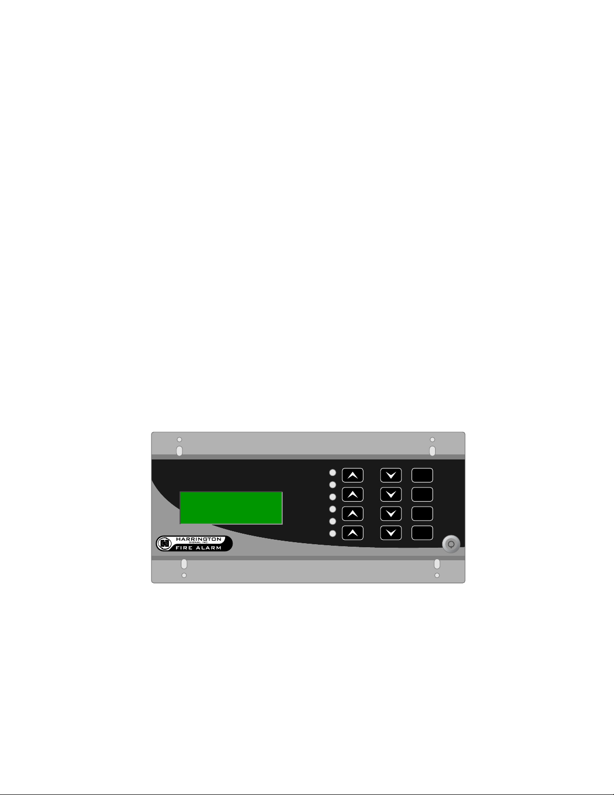
HS-3644
Figure 2: Control Panel Dimensions

HS-3644 Installation and Operating Manual
4
Surface Mount Backbox
Figure 3: Surface Mount Backbox Dimensions

MR-2644 Installation and Operating Manual
5
4.0 Installing the HS-3644
4.1 Wiring
CAUTION: All wiring must be in accordance with applicable codes and standards. An Earth
ground connection must be provided to the back box for transient suppression. This connection
must be made with an approved dedicated earth connection in accordance with NFPA 70, Article
250.
It is recommended that the HS-3644 be powered from the fire panel. However, where an external
power supply is required, the following conditions must be met:
• The power supply must be regulated, power limited and UL listed for Fire applications.
• To ensure proper communications, the negative of the power supply must be connected to
the Aux Power negative of the fire panel.
• The external power supply must be mounted no further than 10ft (3m) from the FACP.
The following sections provide wiring diagrams for the various configurations. Refer to Section 3.4
for a chart of maximum wiring lengths.
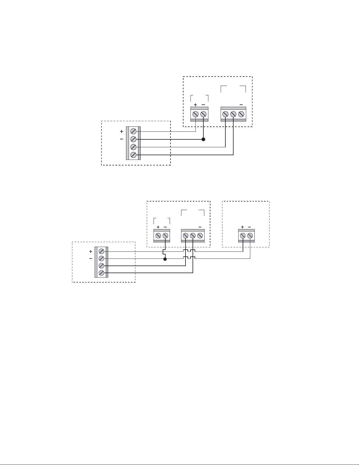
HS-3400 Control Unit
The HS-3400 Control Unit is connected to the HS-3644 Annunciator by four (4) wires, two (2) for
communications and two (2) for power. The communications wiring is polarity sensitive. Refer to
the following diagrams:
HS-3644
HS-3400 HS-3400
HS-3644
Figure 4: HS-3644 connected to HS-
3400 FACP, using HS-3400 Aux Power.
Figure 5: HS-3644 connected to HS-3400 FACP, using
external power supply.
HS-3644 Installation and Operating Manual
6
The HS-3100/3200 Control Unit is connected to the HS-3644 Annunciator by four (4) wires, two (2)
for communications and two (2) for power. The communications wiring is polarity sensitive. Refer
to the following diagram:
AUX
POWER
MR-2100 / 2200
MR-2644
ANN
TXD
RXD
RX
TX
Figure 6: HS-3644 connected to HS-3100/3200
FACP, using HS-3100/3200 Aux Power
HS-3100/3200
HS-3644
AUX
POWER EXTERNAL
POWER SUPPLY
(SEE NOTE)
ANN
NOTE: POWER SUPPLY MUST BE AUL LISTED, 24VDC,
REGULATED, POWER LIMITED POWER SUPPLY FOR
FIRE PROTECTIVE SIGNALING CIRCUITS.
TXD
RXD
RX
TX
MR-2100 / 2200
MR-2644
Figure 7: HS-3644 connected to HS-3100/3200 FACP, using external Power Supply
HS-3100/3200
HS-3644

MR-2644 Installation and Operating Manual
7
HS-3030 Control Unit
The HS-3030 control unit is connected to the HS-3644 Annunciator by four (4) wires, two (2) for
power and two (2) for communications. The wiring is polarity sensitive. The HS-3030 panel
requires that the HS-3109-3 communications board be installed.
HS-3644 HS-3030
HS-3644 connected to HS-3030 FACP,
using HS-3030 Aux Power.
HS-3644
HS-3030
Note: Power supply must be a UL listed, 24VDC, regulated, power
limited power supply for fire protective signaling circuits.
HS-3644 connected to HS-3030 FACP, using external power supply.

HS-3644 Installation and Operating Manual
8
4.2 Connecting Multiple HS-3644 Annunciators
Up to eight (8) HS-3644 remote annunciators can be connected to a single Fire Alarm Control
Panel.
If this is required, it can be done using either "daisy chain" or "home run" methods. Refer to the
wiring specifications in this manual for the guidelines regarding maximum wire length.
HS-3644 Jumper Settings
There are three address jumpers on the back of the printed circuit board. These are labeled J1, J2
and J3. These are used to select one of eight (8) possible addresses on the fire alarm control
panel's annunciator port.
The HS-3644 addresses appear as 9-16 on the fire panel, as 1-8 are used for HS-2802 (LED)
annunciators. The default value is 9, and will need to be changed only if there is more than one
HS-3644 connected to the panel.
Address J1 Setting J2 Setting J3 Setting
9 OFF OFF OFF
10 ON OFF OFF
11 OFF ON OFF
12 ON ON OFF
13 OFF OFF ON
14 ON OFF ON
15 OFF ON ON
16 ON ON ON

HS-3644 Installation and Operating Manual
9
5.0 Mounting
5.1 Flush Mounting
Please refer to Section 1.3 for further details regarding the available ordering options.
1. Choose a suitable place for mounting, observing all applicable codes and standards.
2. Ensure that all power sources to the Fire Alarm Control Panel are disconnected. (This
includes both AC and battery power.)
3. Install a standard 5-gang electrical backbox and run all applicable wiring in accordance
with the wiring specifications described in this manual.
4. Set the addressing jumpers corresponding to the system programming and layout.
5. Connect the field wiring to the terminals on the back of the assembly.
6. Mount the assembly to the 5-gang electrical backbox using the provided screws.
7. Mount the trim-ring using the four painted screws included in the Hardware Pack.
5.2 Surface Mounting
These instructions apply specifically to the HS-3644 when used in conjunction with the HS-
3644SMB or HS3644SM surface mount backbox. Please refer to Section 1.3 for further details
regarding the available ordering options.
1. Choose a suitable place for mounting, observing all applicable codes and standards.
2. Ensure that all power sources to the Fire Alarm Control Panel are disconnected. (This
includes both AC and battery power.)
3. Install the surface-mount backbox using the four mounting holes along with the included
hardware. Feed all applicable wiring through the most convenient knockout in accordance
with the wiring specifications described in this manual.
4. Set the addressing jumpers corresponding to the system programming and layout.
5. Connect the field wiring to the terminals on the back of the assembly.
6. Mount the assembly to the surface-mount backbox using the provided screws.
7. Mount the trim-ring using the four painted screws included in the Hardware Pack.

HS-3644 Installation and Operating Manual
10
6.0 Operating the HS-3644
6.1 Displays
• When the system is normal and AC power is present, the AC ON light is on and all other
lights are off.
• The Alarm, Supervisory, Trouble, Monitor and Ground Fault lights will turn on and off as
the corresponding conditions occur and restore.
• The LCD will show active events identical to the Fire Alarm Control Panel's display.
• The display's backlighting will be on when the annunciator is in use. It will time out after 1
minute without a keypress when AC is present on the system, and after 15 seconds if the
system is running on standby batteries.
6.2 Controls
• The keyswitch enables the Silence and Reset keys. All other keys are available with or
without the key in place.
• The ALM, SUP, TBL and MON scroll keys can be used to view all active events in the
corresponding categories. If there is no event in the category of the key being pressed, it
will scroll through the top level system status screen.
• The ACK key is used to acknowledge and silence Trouble or Supervisory conditions.
• The SILENCE key is used to silence the system's Notification Appliances.
• The RESET key is used to reset the system following off-normal conditions.
• The LAMP TEST key is used to test the annunciator. Pressing this key will cause all lights
to flash and the display to show a test message.
• The user is warned of an illegal entry or function by three quick beeps.
6.3 Miscellaneous
• For more information on detailed menus, refer to the installation/operating guide for the
applicable Fire Alarm Control Panel.
• The main display/keypad of the Fire Alarm Control Panel always takes priority over the
remote annunciator. If the main display/keypad is in use, and a user presses a key at the
annunciator, the remote display will read "System Busy, Please Wait". This will occur until
15 seconds after the last keypress at the main panel.
ALARM ALM
SUP
TBL
MON
ACK
SILENCE
RESET
LAMP
TEST
SUPERVISORY
TROUBLE
MONITOR
AC ON
GROUND FAULT
HS-3644

HS-3644 Installation and Operating Manual
11
7.0 Appendix
7.1 Warranty Procedure
To obtain service under this warranty, please return the item(s) in question to the point of purchase. All authorized distribu-
tors and dealers have a warranty program. Anyone returning goods to Harrington Signal must first obtain an authorization
number. Harrington Signal will not accept any shipment whatsoever for which prior authorization has not been obtained.
Conditions to Void Warranty
This warranty applies only to defects in parts and workmanship relating to normal use. It does not cover:
• Damage incurred in shipping or handling;
• Damage caused by disaster such as fire, flood, wind, earthquake or lightning;
• Damage due to causes beyond the control of Harrington Signal such as excessive voltage, mechanical shock or
water damage;
• Damage caused by unauthorized attachment, alterations, modifications, repair or foreign objects;
• Damage caused by peripherals (unless such peripherals were supplied by Harrington Signal);
• Defects caused by failure to provide a suitable installation environment for the products;
• Damage caused by use of the products for purposes other than those for which it was designed;
• Damage from improper maintenance;
• Damage arising out of any other abuse, mishandling or improper application of the products.
Harrington Signals’ liability for failure to repair the product under this warranty after a reasonable number of attempts will be
limited to a replacement of the product, as the exclusive remedy for breach of warranty.
Limitation of Liability
Under no circumstances shall Harrington Signal be liable for any special, incidental, or consequential damages based upon
breach of warranty, breach of contract, negligence, strict liability, or any other legal theory. Such damages include, but are
not limited to, loss of profits, loss of the product or any associated equipment, cost of capital, cost of substitute or replace-
ment equipment, facilities or services, down time, purchaser's time, the claims of third parties, including customers, and in-
jury to property.
Disclaimer of Warranties
All other obligations or liabilities on the part of Harrington Signal neither assumes nor authorizes any other person purporting
to act on its behalf to modify or to change this warranty, nor to assume for it any other warranty or liability concerning this
product.
WARNING: Harrington Signal recommends that the entire system be completely tested on a regular basis.
However, despite frequent testing, and due to, but not limited to, criminal tampering or electrical disruption, it is possible for
this product to fail to perform as expected.
Out of Warranty Repairs
Harrington Signal will at its option repair or replace out-of-warranty products which are returned to its factory according to
the following conditions. Anyone returning goods to Harrington Signal must first obtain an authorization number. Harrington
Signal will not accept any shipment whatsoever for which prior authorization has not been obtained.
Products which Harrington Signal determines to be repairable will be repaired and returned. A set fee which Harrington Sig-
nal has predetermined and which may be revised from time to time, will be charged for each unit repaired.
Products which Harrington Signal determines not to be repairable will be replaced by the nearest equivalent product avail-
able at that time. The current market price of the replacement product will be charged for each replacement unit.

HS-3644 Installation and Operating Manual
12
7.2 FCC Compliance Statement
CAUTION: Changes or modifications not expressly approved by the manufacturer could void your authority to use this
equipment.
This equipment has been tested and found to comply with the limits for a Class B digital device, pursuant to Part 15 of the
FCC Rules. These limits are designed to provide reasonable protection against harmful interference in a residential instal-
lation.
This equipment generates, uses and can radiate radio frequency energy and, if not installed and used in accordance with
the instructions, may cause harmful interference to radio communications. However, there is no guarantee that interference
will not occur in a particular installation. If this equipment does cause harmful interference to radio or television reception,
which can be determined by turning
the equipment off and on, the user is encouraged to try to correct the interference by one or more of the following measures:
• Re-orient the receiving antenna.
• Increase the separation between the equipment and receiver.
• Connect the equipment into an outlet on a circuit different from that to which the receiver is connected.
• Consult the dealer or an experienced radio/television technician for help.
The user may find the following booklet prepared by the FCC useful: "How to Identify and Resolve Radio/Television Inter-
ference Problems". This booklet is available from the U.S. Government Printing Office, Washington D.C. 20402, Stock #
004-000-00345-4.
Table of contents
Popular Security System manuals by other brands


Lorex
Lorex L19LD1600 Series quick start guide

FRIEDLAND
FRIEDLAND SA5 Installation & operating manual

IBM
IBM SP3001 Hardware configuration guide

Tyco
Tyco Vigilant MX1-Au Wiring diagrams

DPS Telecom
DPS Telecom NetGuardian 216 DCP user manual

Alderon Industries
Alderon Industries VersAlarm I/O VLIO-00005 user guide

jablotron
jablotron OASiS 8 Series quick start guide

Alderon Industries
Alderon Industries Versa'larm VA02A Operation, maintenance and installation manual

ievo
ievo ultimate user guide

Super Circuits
Super Circuits SYRF04 Installation and setup guide

Texecom
Texecom Premier Elite Series user guide

ProVisual
ProVisual WA-1100-K owner's manual