Harris BMXDIGITAL 99-1200-0 User manual

Broadcast
Console
Operations
&
Technical
Manual
PRE75-50PRE75-50
PRE75-50PRE75-50
PRE75-50
Revision D.1 • 12/10
99-1200-0 (14-input mainframe)
99-1200-1 (22-input mainframe)
99-1200-2 (30-input mainframe)
99-1200-3 (38-input mainframe)
99-1200-8 (8-input mainframe)
di
g
ital
BroadcastCommunicationsDivision
www.broadcast.harris.com

Revision D • 8/05
HARRIS CORPORATION
ii

Revision D • 8/05
HARRIS CORPORATION
iii
Contents
CE Declaration of Conformity......................... iv
Safety Instructions .......................................... v
Hazard/Warning Label Identification.............. v
Manual Revisions........................................... vi
1 - GENERAL INFORMATION
Product Overview ........................................1-1
Specifications ...............................................1-4
Warranty......................................................1-6
2 - INSTALLATION
Console Installation......................................2-2
Cabling andWiring ......................................2-7
Module Quick Guides
Mic Preamplifier ...................................2-16
Universal Input .....................................2-18
Telco/Codec ..........................................2-24
RLS ......................................................2-28
Session..................................................2-32
Control Room .......................................2-34
Studio ...................................................2-40
Outputs.................................................2-50
Mic Remote Control Logic Example...........2-58
Basic Peripheral Logic Example.................2-60
Complex Peripheral Logic Example ...........2-62
Net Card ....................................................2-64
3 - OPERATION
Module & Card Overview .............................3-1
Meter Panel Overview ..................................3-1
Microphone Preamplifier Module .................3-2
Universal Input Module................................3-3
Telco/Codec Module.....................................3-6
Telco/Codec Module Operation ....................3-8
Remote Line Selector (RLS) Module ..........3-11
Session Module ..........................................3-12
Control Room Module................................3-14
Studio Module ...........................................3-16
Output Modules .........................................3-17
Meter Panel................................................3-18
Net Cardl ...................................................3-20
4- BMX
digital
SERVERSETUP
RMXd File Structure....................................4-1
RMXd Server Configuration .........................4-5
Session Files...............................................4-14
Session & Macro Files ................................4-16
Software Updates .......................................4-22
Settings Recovery .......................................4-22
5- SERVICE
Parts and Repair Services.............................5-1
Spare and Replacement Parts.......................5-2
Tool and Installation Kits.............................5-3
Module Servicing .........................................5-3
6 - ACCESSORIES
Furniture and Cabinetry ...............................6-1
Furniture Mounted Panels............................6-1
Peripheral Panels .........................................6-2
Headphone Distribution Amplifier ...............6-2
LogicWiring Diagrams & Cables..................6-2
External Remote Line Selector (Ext. RLS) ...6-4
APPENDIX A:VMCC,SESSION &
MACRO FILES
VMCC File Maintenance............................. A-1
Community Monitor................................... A-1
VMCC Operations Errata ........................... A-3
Setup, Config, General File Info .................. A-6
Macro Files ................................................ A-7
INDEX
A - D.....................................................Index-1
E - M ....................................................Index-2
M - S..................................................... Index-3
S -W.....................................................Index-4

Revision D • 8/05
HARRIS CORPORATION
iv
Declaration of Conformity
Application of Council Directive: 89/336/EEC
Standards To Which
EN55103-1:1997
Conformity Is Declared:
EN55103-2:1997
Manufacturer's Name:
Harris Corporation BCD/Harris Pacific
Manufacturer's Shipping Address:
4240 Irwin Simpson Road
Mason, Ohio USA 45040
513-459-3400
Manufacturer's Mailing Address:
4393 Digital Way
Mason, Ohio USA 45040
513-459-3400
Equipment Description:
Digital Broadcast Console
Equipment Class:
Professional Audio / Visual
Model Numbers:
BMX Digital Broadcast Console, Inclusive of
Legacy Digital Product Line
Itheundersigned,herebydeclarethattheequipmentspecifiedabove,
conformstotheaboveDirective(s)andStandard(s).
Harris Corporation – Mason, Ohio USA
Place:
Signature:
Douglas A. Bevington
FullName:
Manager – Product/Technical Services Consoles
and Studio Products
Position:
Revision D • 8/05
HARRIS CORPORATION
v
1. RR
RR
Read Aead A
ead Aead A
ead All Instrll Instr
ll Instrll Instr
ll Instrucuc
ucuc
uctionstions
tionstions
tions..... Read all safety and operating
instructions before operating the product.
2. RR
RR
RetainAetainA
etainAetainA
etainAllInstrllInstr
llInstrll Instr
llInstrucuc
ucuc
uctionstions
tionstions
tions..... Retainallsafetyandoperating
instructions for future reference.
3. HH
HH
Heed Aeed A
eed Aeed A
eed Allll
llll
llWW
WW
Warar
arar
arningsnings
ningsnings
nings.....Youmustadhere toallwarnings
on the product and those listed in the operating
instructions.
4. FF
FF
Folloollo
olloollo
ollow Aw A
w Aw A
w All Instrll Instr
ll Instrll Instr
ll Instrucuc
ucuc
uctionstions
tionstions
tions..... Follow all operating and
product usage instructions.
5. HH
HH
Heaea
eaea
eatt
tt
t..... This product must be situated away from any
heat sources such as radiators, heat registers, stoves,
or other products (including power amplifiers) that
produce heat.
6. VV
VV
Venen
enen
entilatila
tilatila
tilation.tion.
tion.tion.
tion. Slots and openings in the product are
providedforventilation.Theyensurereliableoperation
of the product and keep it from overheating.Do not
block or cover these openings during operation.Do
not place this product into a rack unless proper
ventilation is provided and the manufacturer’s
recommended installation procedures are followed.
7. WW
WW
Waa
aa
att
tt
ter and Mer and M
er and Mer and M
er and Moisturoistur
oistur
oistur
oisturee
ee
e..... Do not use this product near
water such as a bathtub, wash bowl, kitchen sink, or
laundry tub,in a wet basement,or near a swimming
pool or the like.
8. AA
AA
Attachmenttachmen
ttachmenttachmen
ttachmentsts
tsts
ts..... Do not use any attachments not
recommended by the product manufacturer as they
may cause hazards.
9. PP
PP
Poo
oo
oww
ww
wer Ser S
er Ser S
er Sourour
ourour
ourcc
cc
ceses
eses
es..... Youmustoperatethisproductusing
the type of power source indicated on the marking
label and in the installation instructions.If you are not
sure of the type of power supplied to your facility,
consultyourlocalpowercompany.
10. GG
GG
Grr
rr
rounding and Pounding and P
ounding and Pounding and P
ounding and Polarolar
olarolar
olarizaiza
izaiza
ization.tion.
tion.tion.
tion. This product is
equippedwithapolarizedACplugwithintegralsafety
ground pin. Do not defeat the safety ground in any
manner.
11. PP
PP
Poo
oo
oww
ww
werCerC
erCerC
erCoror
oror
ord Pd P
d Pd P
d Prr
rr
rotot
otot
otecec
ecec
ection.tion.
tion.tion.
tion.Powersupplycordsmustbe
routed so that they are not likely to be walked on nor
pinched by items placed upon or against them.Pay
particular attention to the cords at AC wall plugs and
convenience receptacles,and at the point where the
cord plugs into the product.
12. LighLigh
LighLigh
Lightningtning
tningtning
tning..... For added protection for this product,
unplug it from the AC wall outlet during a lightning
storm or when it is left unattended and unused for
long periods of time.This will prevent damage to the
product due to lightning and power line surges.
13. OO
OO
Ovv
vv
verer
erer
erloadingloading
loadingloading
loading..... Do not overload AC wall outlets,
extensioncords,orintegralconvenienceoutletsasthis
can result in a fire or electric shock hazard.
14. OO
OO
Objecbjec
bjecbjec
bject and Liquid Et and Liquid E
t and Liquid Et and Liquid E
t and Liquid Enn
nn
ntrtr
trtr
tryy
yy
y..... Never push objects of any
kind into this product through openings as they may
touch dangerous voltage points or short out parts,
whichcould resultinafireorelectricshock.Neverspill
liquid of any kind on the product.
15. AA
AA
Acccc
cccc
ccessoressor
essoressor
essoriesies
iesies
ies..... Donotplacethisproductonan unstable
cart, stand, tripod, bracket, or table.The product may
fall,causingseriousinjurytoachildoradultandserious
damagetotheproduct.Anymountingoftheproduct
must follow manufacturer’s installation instructions.
Safety Instructions16. PP
PP
Prr
rr
roo
oo
oducduc
ducduc
duct and Ct and C
t and Ct and C
t and Carar
arar
art Ct C
t Ct C
t Combinaombina
ombinaombina
ombination.tion.
tion.tion.
tion. Move this product
with care. Quick stops, excessive force, and uneven
surfaces may cause the product and the cart
combination to overturn.
17. SS
SS
Serer
erer
ervicingvicing
vicingvicing
vicing..... Refer all servicing to qualified servicing
personnel.
18. DD
DD
Damage Ramage R
amage Ramage R
amage Requirequir
equirequir
equiring Sing S
ing Sing S
ing Serer
erer
ervicvic
vicvic
vicee
ee
e..... Unplug this product
fromthewallACoutletandreferservicingtoqualified
service personnel under the following conditions:
a. When the AC cord or plug is damaged.
b. If liquid has been spilled or objects have fallen into
the product.
c. If the product has been exposed to rain or water.
d. If the product does not operate normally (following
operating instructions).
e. If the product has been dropped or damaged in any
way.
f. When the product exhibits a distinct change in
performance.This indicates a need for service.
19. RR
RR
Replaceplac
eplaceplac
eplacemenemen
emenemen
ement Pt P
t Pt P
t Parar
arar
artsts
tsts
ts..... When replacement parts are
required, be sure the service technician has used
replacement parts specified by the manufacturer or
thathavethesamecharacteristicsastheoriginalparts.
Unauthorized substitutions may result in fire,electric
shock, or other hazards.
20. SS
SS
Safaf
afaf
afetet
etet
ety Cy C
y Cy C
y Check.heck.
heck.heck.
heck.Uponcompletionofanyrepairstothis
product,ask the service technician to perform safety
checks to determine that the product is in proper
operating condition.
21. CC
CC
Cleaningleaning
leaningleaning
leaning..... Do not use liquid or aerosol cleaners.Use
only a damp cloth for cleaning.
WW
WW
WARNINGARNING
ARNINGARNING
ARNING—Thisequipmentgenerates,uses,andcanradiateradiofrequencyenergy.Ifnotinstalledand used in accordancewiththe instructionsin this
manual it may cause interference to radio communications. It has been tested and found to comply with the limits for a Class A computing device
(pursuanttoSubpartJof Part15FCCRules),whicharedesigned toprovidereasonableprotectionagainstsuch interferencewhen operated in acommer-
cial environment. Operation of this equipment in a residential area is likely to cause interference,in which case the user, at his own expense,will be
required to take whatever measures may be required to correct the interference.
Hazard/Warning Label Identification
The LighLigh
LighLigh
Lightning Ftning F
tning Ftning F
tning Flashlash
lashlash
lashWW
WW
Withith
ithith
ith
AA
AA
Arr
rr
rrr
rr
roo
oo
owhead symbwhead symb
whead symbwhead symb
whead symbolol
olol
ol,within an
equilateral triangle,alerts the user to
the presence of uninsulated
dangerous voltage within the
product’s enclosure that may be of
sufficient magnitude to constitute a
risk of electric shock.
The EE
EE
Exx
xx
xclamaclama
clamaclama
clamation Ption P
tion Ption P
tion Poinoin
oinoin
oint symbt symb
t symbt symb
t symbolol
olol
ol,
within an equilateral triangle,alerts the
user to the presence of important
operating and maintenance (servicing)
instructions in product literature and
instruction manuals.
RISK OF ELECTRIC SHOCK
DO NOT OPEN
CAUTION
WARNING:SHOCK HAZARD - DO NOT OPEN
AVIS: RISQUE DE CHOC ELECTRIQUE - NE PAS OUVRIR
CAUTION:TO REDUCETHE RISK OF ELECTRIC SHOCK DO NOT
REMOVE ANY COVER OR PANEL.NO USER SERVICEABLE PARTS
INSIDE.REFER SERVICINGTO QUALIFIED SERVICE PERSONNEL.
WARNING:TO REDUCETHE RISK OF FIRE OR ELECTRIC
SHOCK,DO NOT EXPOSETHE POWER SUPPLY OR CONSOLE
TO RAIN OR MOISTURE.

Revision D • 8/05
HARRIS CORPORATION
vi
This page provides a quick reference of the
current document pages and their revision level. If
youreceivearevisiontothisdocument fromHarris,
replacetheold manual pageswiththenewones and
discard the old pages. Replace this page with the
new Manual Revisions page.
Revision Affected pages Comments
A All pages 10/01 First Release
A.1 Contents, Ch 1, Index 12/01 corrected info
in Specifications.
B All pages 8/02 updated various
installation and
operation information.
Incorporated firmware
and hardware
updates.
B.1 Appendix B pages 3/03 add software
release 3.24 info.
C All pages 1/04 Added info on the
BMXd-8 & BMXd-14
frame sizes and the
VistaMax audio
management system.
D Contents,Ch. 4, 5, Added information on
Appendix A, index VMCC.
Manual Revisions

Revision C • 1/04
HARRIS CORPORATION
1-1
1
di
g
ital
Thanks for joining the growing ranks of
broadcasters employing Harris Corporation prod-
ucts designed by PR&E. Our mission: provide the
finestqualityproducts,systems,documentationand
after-salesupport.
The BMX
digital
is a very sophisticated console
with an extensive range of features contained in a
compactdesign.Toobtainmaximumbenefit from
theconsole’scapabilities,readthe
Installation
and
Operation
sections prior to product installation.
Product Overview
EachBMX
digital
consoleships with the follow-
ing installed into the mainframe assembly:
•Microphone Preamplifier Module
(1 Mic Preamp standard, 1 optional)
•Universal Input Modules (as ordered)
•Telco/Codec Modules (up to 6,as ordered)
•Remote Line Selector modules (asordered)
•Session Module (1 standard)
•Control Room Module (1 standard)
•Studio Module (1 optional)
•Output Modules (3 standard)
•DSPCards(1to 5, dependingonframesize)
•Net Card (1 optional)
•Blank Panels (as required)
The BMX
digital
’s motherboard and module/
card area is surrounded by a sheet metal and ex-
trudedaluminumchassisforstrengthandRFIim-
munity.The meterpanel—hingedattherear,closes
over the upper part of the modules, covering the
audio and logic connectors,the DIP switches and
DSP and Net Cards. Cable access to modules is
done from below the meter panel.
MODULE & CARD DESCRIPTIONS
Full-featured Input modules are described
throughoutthismanual.Limited-functionversions
(minusthe Send or Utility bus controls), Net-only
versions (no connectors) and Limited-function
Net-only versions (no connectors nor Send and
Utility bus controls) are also available.
MicrophonePreamplifierModule
Five mic preamps,each with a trim pot under a
securitycover,comestandard on the BMX
digital
-
8 and -14. Ten preamps come standard on the
other frame sizes.A second five or ten input Mic
Preamp Module can be field installed.
Mic preamps take balanced input signals (from
-65dButo -30 dBu) andoutput balanced +4 dBu
outputsfor direct connection toa UniversalInput
module or to outboard processing equipment.
UniversalInputModule
This module features two inputs (A and B),each
can come from an analog or a digital source
(source selection is set via a module DIP switch).
DIP switches also set the analog input level or the
digital attenuation. Each input has a fully inde-
pendent parallel logic circuit for remote control
ofthemoduleand/ormodulecontrolofthesource
equipment. Each module has independent mic/
General
Information

Revision C • 1/04
HARRIS CORPORATION
1-2
1 General Information
di
g
ital
an analog input (active input set by module DIP
switch). Front panel controls are the same as the
UniversalInput,minus theA/B selection.Instead,
there is a Source Selector andTake button.
SessionModule
This module providessessioncontrol,auxiliary
meter source selection, and event timer controls.
There are eleven Aux Meter selector buttons (for
viewing any External Input,Send, Utility bus, or
TelcoRecordoutput) andtwoMainMeterselectors
(PGM1-4 and UTL 1-4)for viewing the Program
or the Utility buses on the four Main Meters (on
the BMX
digital
-8, the two buttons cycle through
thebusestoshow oneatatimeontheMain meter).
The session control section has a Session
Selector and two buttons:Take and Save.A two-
linedisplayshows the session currently being used
and either the next session to be loaded, or when
the Session Selector is being turned, the various
sessions available in alphanumeric order.
The Timer Control section has the event timer
controls: Start, Stop, Hold, and Reset, as well as
the Auto Reset control, which adds automatic
module on resetting of the event timer.
ControlRoom Module
This module hasthe monitor selection andcon-
trolfacilities for the console operator.It has paral-
lellogic control for control room speaker dim and
mute,and to provide a controloutput for the Con-
trol Room warning lamp controller.
The Control Room module has independent
monitorandheadphone sourceselectorsandmoni-
tor and headphone fader level controls.The mod-
ule also has input mode controls, Cue and talk-
back level controls and a solo clear button.Addi-
tional headphone controls include an Autocue se-
lector and a button to force the headphones to
follow the monitor source selection.
line logic functions for both inputs,also set using
the module’s Setup DIP switches.
The Universal Input module has controls for the
following functions: A/B input selection, input
mode selection, channel on/off, fader level, solo,
cue, pan/balance, two Send selectors and level
controls, and ten output bus selectors (four pro-
gram, four utility, and two off-line buses).A two-
linedisplayshowstheAandBinputsource names.
Two 24-pin connectors connect logic wiring to/
fromexternalperipheralsor control panels for the
A and B inputs.Two 14-pin connectors allow re-
mote talkback (active when microphone logic is
selected) for the A and B inputs. Four 8-position
DIP switches set logic and module function op-
tions independently for the A and B inputs.
Telco/CodecInput Module
An optional module that provides audio and
logicconnectionsforatelephonehybridoracodec
(satellite transceiver, ISDN interface, etc.). Up to
sixTelco modules can be installed in the frame.
Telco modules have digital and analog inputs
(the active input is set via DIP switch) and the
same controls as a Universal Input—minus the
A/Binputselector.Additionalmodulecontrolsin-
clude: telco monitor bus and telco record output
assignment buttons, a Talk to Codec function, a
Source Selector and aTake button (for source se-
lection with aVistaMax, Ext. RLS or a router).
Each Telco module has an associated mix-
minus (Foldback) of any combination of the pro-
gram, utility or send buses and two off-line mix
buses. An Auto-Foldback function can automate
switching Foldback between an off-line mix and
the assigned bus with module off and on.
RemoteLineSelectorInputModule
An optional module that offers source selection
from aVistaMax system, an external remote line
selectorora router.Each module has a digitaland

Revision C • 1/04
HARRIS CORPORATION
1-3
1 General Information
di
g
ital
StudioModule
This optional module has the monitoring and
talkbackcontrolsfortwoseparatestudiosor voice
booths, plus talkback audio and control inputs
for a producer/call screener position and for an
externalposition.
The Producer and External audio inputs are
line level.The Mic Preamp module may be used
asneeded for these inputs.AProducerTalkback/
IFB Panel (PRE99-1188) is also available.It pro-
vides a mic and preamp for the Producer along
withTalk buttons for thirteen locations.
The Studio module has two parallel logic con-
nectorsforthe Studio 1 and 2 dim,mute,and Stu-
dioWarning Lamp interface controls.
The Studio module also has monitor and talk-
back selector controls,and monitor and talkback
level controls.All of the controls operate indepen-
dently for each studio.
OutputModules
There are three Output modules.The Output 1
module has the digital-to-analog converters and
mix matrices for creating mix-minus foldbacks to
supportuptosixTelco/Codecmodules.Italsocon-
tains individually mixed outputs for Telco moni-
toring and recording.Two monaural mix-minus
outputs for each Telco/Codec module, one with
talkback (IFB) and one with a clean feed, are on
this module.
Digital and analog outputs are provided for the
mix-minus and recorder feed outputs. For digital
outputs, sample rates of 48 kHz and 44.1 kHz
are supported.The mix-minus analog outputs are
fixed at +4 dBu. This module features output
sample rate selectors for digital outputs and gain
trim controls for the analogTelco record mix out-
put and IFB level.
The Output 2 and Output 3 modules contain
the AES digital output drivers, digital-to-analog
converters,and analog line amplifiers for the Pro-
gram, Utility, and Send outputs. For digital out-
puts, sample rates of 48 kHz and 44.1 kHz are
supported.These modules feature output sample
rate selectors for the Program auxiliary outputs
and the Utility and Send outputs, as well as gain
trim controls for the Program, Utility, and Send
analog outputs.
DSPCards
The number of standard DSP (Digital Signal
Processor)cardsinstalled is frame-size dependent
(BMX
d
-8 has one DSP Card,BMX
d
-14 has two,
and so on up to the BMX
d
-38 with five cards).
DSP cards plug into the motherboard behind
the input modules,hidden below the meter panel
in normal use. Each card has a“heartbeat”LED
to indicate operation.An optional External Input
DSP (99-1355-1) adds an external AES-3 refer-
ence input for the first DSP Card position.
NetCard
Thisoptional card allows the BMX
digital
todi-
rectlyinterface to aVistaMaxAudioManagement
System. It plugs into the motherboard behind the
Output modules,hidden below the meter panel in
normal use.There are eightVistaMax inputs and
outputs on the card for connecting intercom, ex-
ternalmonitorsandotherin-roomequipmentthat
does not need to have local module control.
POWERSUPPLY
The separate rack-mount power supply (99-
1205) supplies +48 VDC and a voltage monitor
signalto the console. One supplycomes standard.
An optional second 99-1205 supply and a +48
VDC Coupler (99-1203) can be installed for re-
dundantsupplyoperation.Eachpowersupplyhas
its own AC input,On/Off switch and LED power
good indicator. Each power supply is fully regu-
lated and protected against excessive current by
internal fuses and electronic safeguards.

Revision C • 1/04
HARRIS CORPORATION
1-4
1 General Information
di
g
ital
Specifications
The specifications for the BMX
digital
are sig-
nificantlymorecomplete,and the related test con-
ditionsaremoredefined,than those usually shown
for consoles in this class.Be sure to follow the test
conditions and measure in the units as stated.
The specifications are for a fully loaded BMX-
digital
38-input mainframe.
Test Conditions:
Specificationsare for the basic signal paths,per
channel, with >1 k ohm loads connected to the
analog main outputs.
0 dBu corresponds to an amplitude of 0.775
voltsRMS regardless ofthecircuitimpedance.This
is equivalent to 0 dBm measured into a 600 ohm
circuit for convenient level measurement with
meterscalibratedfor 600ohmcircuits.Noisespeci-
fications are based upon a 22 kHz measurement
bandwidth.The use of a meter with 30 kHz band-
width will result in a noise measurement increase
of approximately 1.7 dB.
Total Harmonic Distortion (THD+N) is mea-
sured at a +18 dBu output level using a swept
signal with a 22 kHz low pass filter.
FSD = Full Scale Digital, +24 dBu
Microphone Preamplifiers
Source Impedance: 150 ohms
Input Impedance: 5 k ohms minimum, balanced
Input Level Range: Adjustable,-65 to -30 dBu
Input Headroom: >20 dB above nominal input
Output Level: +4 dBu, nominal
Analog Line Inputs
Input Impedance: >40 k ohms, balanced
Input Level Range: Selectable, -10 dBv, +4 dBu,
+6 dBu, +8 dBu
Input Headroom: 20 dB above nominal input
Analog Main Outputs
Output Source Impedance: <3 ohms balanced
Output Load Impedance: 1 k ohms minimum
Nominal Output Levels: Program,Utility,Send,Telco/
Codec Mix-Minus,Telco Record Mix Feed: +4
dBu, adjustable between +3 dBu and +9 dBu
Maximum Output Levels: Program, Utility, Send,
Telco/CodecMix-Minus,TelcoRecordMixFeed:
+24 dBu; +28 dBu with nominal output level
adjusted to +8 dBu
Digital Inputs and Outputs
Reference Level: +4 dBu (-20 dB FSD)
Digital I/O:Thru digital input and digital Program,
Utility, Send,Telco/Codec Mix-Minus outputs
Signal Format: AES-3, S/PDIF (input only)
AES-3 Input Compliance:
24-bit sample rate conver-
sion available,individually switch selectable
AES-3 Output Compliance:
24-bit
Digital Reference:
Crystal (internal) or AES-3 (ex-
ternal) at 48 kHz ±100 ppm
Internal Sample Rate:
48 kHz
Output Sample Rates: Program Main outputs are
48 kHz;Program Aux,Utility, Mix-Minus and
Telco Record Mix outputs, individually DIP
switch set for 48 kHz or 44.1 kHz
Processing Resolution:
24-bit fixed with extended
precision accumulators
Conversions:
A/D 24-bit, Delta-Sigma, 128x
oversampling on all digital inputs; D/A 24-bit,
Delta-Sigma,128x oversampling
Latency:
<1.6 ms,mic in to monitor out
Monitor Outputs
Output Source Impedance: <3 ohms,balanced
Output Load Impedance: 1 k ohms minimum
Output Level: +4dBunominal,+24 dBu maximum
Frequency Response
Microphone or Line Input to Program, Utility, or Send
Output: +0 dB/-0.5 dB, 20 Hz to 20 kHz

Revision C • 1/04
HARRIS CORPORATION
1-5
1 General Information
di
g
ital
Dynamic Range
Analog Input to Analog Output: 105 dB referenced to
FSD, 108 dB“A”weighted to FSD
Analog Input to Digital Output: 109 dB referenced to
FSD
Digital Input to Analog Output: 107 dB referenced to
FSD, 110 dB“A”weighted to FSD
Digital Input to Digital Output: 138 dB
Equivalent Input Noise
Microphone Preamp:-127 dBu, 150 ohm source
Total Harmonic Distortion + Noise
Mic Pre Input to Mic Pre Output: <0.005%, 20 Hz to
20 kHz, -38 dBu input, +18 dBu output
Analog Input to Analog Output: <0.005%, 20 Hz to
20 kHz, +18 dBu input, +18 dBu output
Digital Input to Digital Output:
<0.00016%,20 Hz to
20 kHz, -20 db FSD input, -20 db FSD output
Digital Input to Analog Output:
<0.005%, 20 Hz to
20 kHz, -6 db FSD input, +18 dBu output
Crosstalk Isolation
Program-to-Program or to-Utility or to-Send:
>95 dB,
20 Hz to 20 kHz
A Input to B Input, B Input to A Input:
>110 dB,20 Hz
to 20 kHz
Stereo Separation
Analog Program Outputs:
>86 dB,20 Hz to 20 kHz
Console Power Requirements
Fully configured BMXdigital 22: 250 watts at 115/
230VAC, ±12%, 50/60 Hz
Fully configured BMXdigital 30: 285 watts at 115/
230VAC, ±12%, 50/60 Hz
Fully configured BMXdigital 38
:
320 watts at 115/
230VAC, ±12%, 50/60 Hz
Power SupplyVoltage
Console power: +48 VDC at 6.25 Amps,
optional redundant supply can be added with
48 volt coupler
Power Supply Ground
Rack mounted power supply: grounded thru AC cord
Power Supply Connection
AC input: IEC power cord, one per plug-in power
supply
DC output: Keyed multi-pin connectors
Dimensions
BMXd-8: 9.8" [249] x 29.2" [742] x 33.4" [848]
BMXd-14: 9.8" [249] x 42.0" [1067] x 33.4" [848]
BMXd-22: 9.8" [249] x 54.8" [1392] x 33.4" [848]
BMXd-30: 9.8" [249] x 67.6" [1717] x 33.4" [848]
BMXd-38: 9.8" [249] x 80.4" [2042] x 33.4" [848]
48V Power Supply (Rack mount): 2 RU: 3.5" [89] x
19" [483] x 10" [254]
48V Coupler (Rack mount): 1 RU: 1.75" [45] x 19"
[483] x 10" [254]
All dimensions are Height,Width, Depth.
HarrisCorporation reserves the right to change
specifications without notice or obligation.

Revision C • 1/04
HARRIS CORPORATION
1-6
1 General Information
di
g
ital
E) This Warranty is void for equipment which
has been subject to abuse, improper installa-
tion, improper operation, improper or omit-
ted maintenance, alteration, accident, negli-
gence(in use, storage, transportation, or han-
dling), operation not in accordance with
Seller’s operation and service instructions, or
operation outside of the environmental con-
ditions specified by Seller.
F) ThisWarranty is the only warranty made by
Seller, and is in lieu of all other warranties,
includingmerchantabilityandfitness for apar-
ticularpurpose,whetherexpressedorimplied,
except as to title and to the expressed specifi-
cations contained in this manual.Seller’s sole
liability for any equipment failure or any
breach of thisWarranty is as set forth in sub-
paragraph A) above; Seller shall not be liable
or responsible for any business loss or inter-
ruption,or other consequentialdamagesofany
nature whatsoever, resulting from any equip-
ment failure or breach of this warranty.
WARRANTY
The BMX
digital
consoleand power supplycarry
a manufacturer’s warranty which is subject to the
following guidelines and limitations:
A) Except as expressly excluded herein, Harris
Corporation (“Seller”) warrants equipment of
its own manufacture against faulty workman-
ship or the use of defective materials for a pe-
riod of one (1) year from date of shipment to
Buyer.Theliability of the Seller underthisWar-
rantyis limited to replacing,repairing,or issu-
ing credit (at the Seller’s discretion) for any
equipment, provided that Seller is promptly
notified in writing within five (5) days upon
discovery of such defects byBuyer,and Seller’s
examination of such equipment shall disclose
to its satisfaction that such defects existed at
the time shipment was originally made by
Seller, and Buyer returns the defective equip-
ment to Seller’s place of business in Mason,
Ohio, packaging and transportation prepaid,
with return packaging and transport guaran-
teed.
B) Equipment furnished by Seller, but manufac-
tured by another, shall be warranted only to
theextentprovidedby the other manufacturer.
C) Thermal filament devices, such as fuses, are
expressly excluded from this warranty.
D) The warranty period on equipment or parts
repaired or replaced under warranty shall ex-
pire upon the expiration date of the original
warranty.
2
di
g
ital
Revision C • 1/04
HARRIS CORPORATION
2-1
5.75"
[146]
11.8"
[300]
4.00"
[102]
0.75"
[19]
33.4"
[848]
4.00"
[102]
2.50"
[63.5]
14.00
"
[356]
2.50"
[63.5]
COUNTERTOP
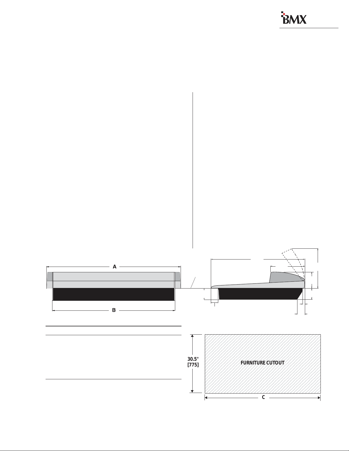
DimensionTable
Mainframe A B C
BMXdigital-8 29.2"[742] 26.1"[663] 26.4"[671]
BMXdigital-14 42.0"[1067] 38.9"[988] 39.2"[996]
BMXdigital-22 54.8"[1392] 51.7"[1313] 52.0" [1321]
BMXdigital-30 67.6"[1717] 64.5"[1638] 64.8" [1646]
BMXdigital-38 80.4"[2042] 77.3"[1963] 77.6" [1971]
Millimeter dimensions in brackets. All dimensional tolerances are: +¼"
[6.4], -0" [0.0]. Typical setback from countertop edge to the front of the
console is 12" [305]. There must be 14" [356] of clearance above the
countertop to open up the meter panel.
The BMX
digital
mainframe“drops into”
a cutout (shown below) in the studio furniture
countertop.A minimum of 14 inches [356 mm] of
verticalclearanceabove the countertop is required
to fully open the meter panel.The rear 2.5 inches
[63.5 mm] of the mainframe bottom is open so
wiringcan be easily dressedup through the main-
frame to the module connectors, which are hid-
den below the meter panel in normal use.
The BMX
digital
console shipment consists of:
• The 8, 14, 22, 30 or 38 input frame with the
standard modules (Mic Preamp, Session, Con-
trol Room, three Outputs and DSP Cards) in-
stalled.Alsoinstalledare anyoptionalitems that
were also ordered (Universal Input, Telco/Co-
decand RLS modules,blankpanels,Net Card).
• A 2RU rack-mount 48 volt power supply with
interconnecting cable.
• A BMX
digital
Tool kit (3 AA batteries, AMP
MOD IV crimp tool and contact removal tool,
hex driver, and module removal tool).
• Audio and logic connector kit.The kit contains
all the AMP MOD IV connector housings and
receptacle contacts typically needed for instal-
lation.
Installation
Console,backview
Console,sideview,withdimensions
123456789012345678901234567890121234567
1
2345678901234567890123456789012123456
7
1
2345678901234567890123456789012123456
7
1
2345678901234567890123456789012123456
7
1
2345678901234567890123456789012123456
7
1
2345678901234567890123456789012123456
7
1
2345678901234567890123456789012123456
7
1
2345678901234567890123456789012123456
7
1
2345678901234567890123456789012123456
7
1
2345678901234567890123456789012123456
7
1
2345678901234567890123456789012123456
7
1
2345678901234567890123456789012123456
7
1
2345678901234567890123456789012123456
7
1
2345678901234567890123456789012123456
7
1
2345678901234567890123456789012123456
7
1
2345678901234567890123456789012123456
7
1
2345678901234567890123456789012123456
7
1
2345678901234567890123456789012123456
7
1
2345678901234567890123456789012123456
7
123456789012345678901234567890121234567
FURNITURE CUTOUT
C
30.5"
[775]
Revision C • 1/04
HARRIS CORPORATION
2-2
2 Installation
di
g
ital
MAINFRAME CONFIGURATION
The BMX
digital
designpositionsthe input mod-
ules in the physical center of the mainframe.This
givesthe operator equal reach to peripheral equip-
ment located to either side of the console.
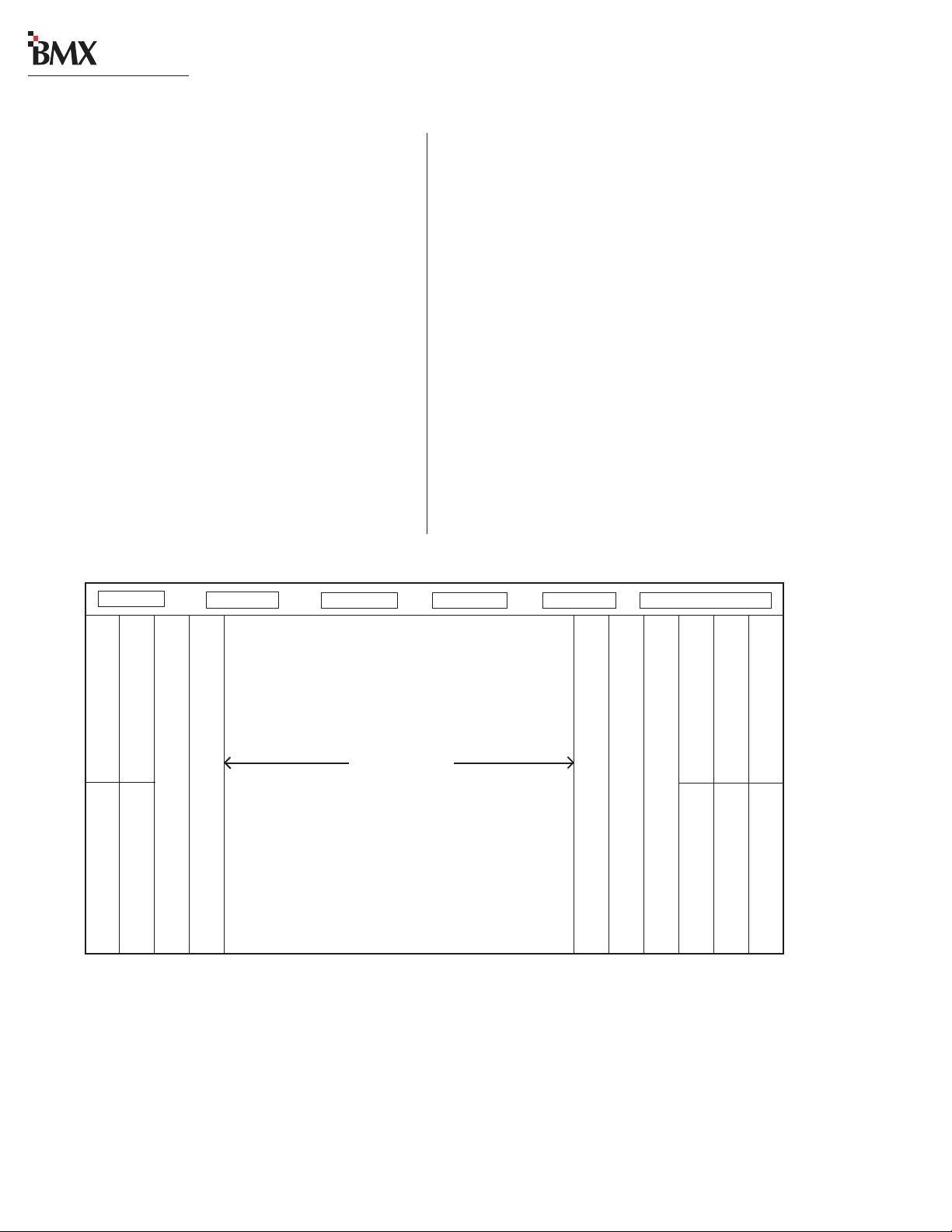
ModulePlacement
The 8, 14, 22, 30 or 38 input module positions
can have any combination or order of the follow-
ing modules installed: Universal Input, Telco/
Codec (sixmaximum), and Remote LineSelector
(RLS).The remaining console positions are fixed.
The Microphone Preamp module(s),Sessionmod-
ule, Control Room module, optional Studio mod-
ule, and Output modules must be positioned as
shown below.
Console Installation
To simplify console installation,logic cable wir-
ingdiagramsforspecificperipheralequipmentare
available from HarrisTechnical Support.Refer to
page 5-1 for contact information.
INSTALLATION NOTE: Do not locate the con-
solenear intense electromagnetic hum fields,such
as those produced by large power transformers
andbyaudioamplifiersthat use inexpensivepower
transformers operating in or near saturation.
Strong electromagnetic fields may impair the per-
formance of the BMX
digital
and neighboring
equipment. Route audio cables to achieve maxi-
mum practical distance from all AC power mains
wiring.
Reserved position (coveredby a 25" Blank panel) ***
Reserved position (coveredby a 25" Blank panel) ***
Session (standard)
ControlRoom(standard)
Studio(optional) 25”blank panel (standard)
BMXdigital Mainframe,Module Configuration
Mic Preamp (standard)
Output 1 (standard)
Output 2 (standard)
Output 3 (standard)
NOTE:NOTE:
NOTE:NOTE:
NOTE:The number of input module positions matches the console model number (e.g., BMXdigital-22 has 22 input positions). There is
one DSP card in the BMXd-8, two DSP cards in the BMXd-14, three in the BMXd-22, four in the BMXd-30, and five in the BMXd-38.
The areas covered by the five 12.25" Blank Panels can be used for mounting Harris BMXdigital Accessory Panels or custom remote
control panels. Since the Harris BMXdigital Accessory Panels are 6" long, a PRE99-1100 Divider Kit (for mounting up to four Accessory
Panels in place of two 12.25" Blank Panels), or a PRE99-1101 Divider Kit (for mounting up to six Accessory Panels in place of three
12.25" Blank Panels) is required. Typically, the PRE99-1100 Divider Kit is installed in place of the Blank Panels on the left end of the
console and the PRE99-1101 is installed in place of the Blank Panels on the right end of the console. 6" Blank Panels (PRE99-1714-3)
cover unused Accessory Panel positions.
Inputmodules
Theinput module positionsare filled
withany combinationornumber of
UniversalInputand RemoteLine
Selectormodules,and upto sixTelco/
Codecmodules.Unused positions are
coveredwith 25"Blank Panels.
12.25"Blank Panel (standard)
12.25"Blank Panel (standard)
12.25"Blank Panel (standard)
12.25"Blank Panel (standard)
12.25"Blank Panel (standard)
DSPCard1 DSPCard2* DSPCard 3* DSPCard4* DSPCard 5* Net Card**
*ThenumberofDSP Cardsusedis setby theframesize.
**The optionalNet Cardis used with theVistaMax Audio ManagementSystem.
***These two slotsare input modulepositions 1 and2 on theBMXdigital-8 frame.
Mic Preamp 2 (optional)
12.5”blank panel (standard)

2 Installation
di
g
ital
Revision C • 1/04
HARRIS CORPORATION
2-3
MeterPanel
The meter panel has five horizontal Stereo Bar-
graphMeters,except forthe BMX
digital
-8,which
has two meters. An alphanumeric display below
each meter identifies the current signal source
(PROGRAM 1,UTILITY 1, etc.).
Four of the meters provide simultaneous level
monitoringof the four Programor the four Utility
bus outputs, as selected by two Session module
buttons. On the BMX
digital
-8, these two Session
module buttons cycle through the four Program
and the four Utility buses to select which bus to
display on the single main meter.
The right-hand meter (Auxiliary)shows the Cue
or Solo bus levels.When neither function is ac-
tive,the meter shows a source selected on the Ses-
sion module (from between the four external in-
puts, the two Sends, the four Utility buses or the
Telco Record output).
The meter display mode (peak hold or non-peak
hold)and the level wherethe peak indicators turn
onare set for each metervia DIP switches on each
meter display board.
On the left end of the meter panel is an ESE-
slaveable 12/24-hour digital clock (on all sizes
except for the BMX
digital
-14). On the right end
there is an event timer that can be controlled
manually, through buttons on the Session mod-
ule, or automatically, through module On reset
commands.
CONNECTOR ACCESS
Module connectors are hidden below the meter
panel, which is hinged on the rear of the main-
frame.Toaccess the connectors,open up the meter
panelbyliftinguponthemiddleofthemeterpanel
while allowing it to pivot rearward to fully extend
the two gas springs.
Caution: Make sure the panel is open all the
way so that it does not accidentally fall shut.
To facilitate initial wiring, the meter panel can
be entirely removed from the mainframe:
1Open up the meter panel fully and unplug
the meter power cable (attached to the rear
panel)andthethree signal cables pluggedinto
the Session module.
2With another person assisting to hold the
meter panel, remove the screw and bushing
thatattacheachgasspringtothemeterpanel.
Lay the gas springs on the mainframe while
working.
3Unlatchthehingesbymoving the release pins
to their unlocked positions and lift the meter
panel up and off the mainframe.
Toreinstall the meter panel,alignthetwohalves
of the hinges, then release the pins out of their
unlockedpositions.
Reattach each gas spring to the meter panel by
inserting a screw through the gas spring and the
bushing.
Main Meters
(BMXdigital-8only has onemeter)
Two Session module switches select
whetherthe Programor theUtility
Busesare displayed
Clock
(not available on
the BMXdigital-14)
Event
Timer
Auxiliary Meter
(Cue,Solo,orSession
module-switched source)
BMXdigital Meter Panel

Revision D.1 • 12/10
HARRIS CORPORATION
2-4
2 Installation
di
g
ital
POWERSUPPLY
The 99-1205 power supply requires 2 RU of
rackspacewithintheconsolecabinetry,below and
to the left or right of the supporting countertop.
The 48 Volt Power Supply must be installed so
that the 30 foot power supply cable (90-1709) is
not under any tension when routed through the
cabinet and connected to the mainframe’s rear
panel connectors.
Connecting thePowerSupply
The power supply cable has two connectors:
• A 5-pin connector to supply 48 volt DC
power to the console.
• A 4-pin connector to supply power status
information (Imminent Power Loss) to the
console.
Both connectors must be attached to the back
of the BMX
digital
and to the power supply.
DC GROUNDING NOTE:
Do not
connect
the audio or logic supply
ground wiring to the chassis of the
power supply.
AC GROUNDING NOTE: Do not
defeat the safety ground in any way.
Doing so may provide a potentially
dangerous condition to the operator.
RedundantPowerSupply
To provide redundant console power, two
99-1205 power supplies can be connected to the
console through a 99-1203 48Volt Coupler.
GROUNDING AND SHIELDING
The broadcast facility’s technicalgroundcanbe
connected to the mainframe chassis using the
threaded insert on the rear of the console (shown
in the Power Connections drawing on this page).
Use a 10-32 screw and crimp lug to terminate the
facility’s technical ground wire.
Connect the cable shields at both the console
and the peripheral end when all system compo-
nents share a common ground potential and are
usingisolated groundAC outlets tied individually
back to the main technical ground.
If isolated ground AC outlets are not available,
connect the cable shields at the console end only.
The shields should be floated (left unconnected)
at the peripheral device end. Ensure the periph-
eral devices connect to a clean ground through
their power cords, or through separate ground
wires to the facility’s technical ground.
POWER SUPPLY GROUNDING NOTE:
The PowerSupplychassisconnectstothe
AC mains safety or“U”ground wire.
AUDIOGROUNDNOISES: Buzz pickup is gener-
ally electrostatic—such as capacitive coupling
between an audio line and a power line.To avoid
audio ground noises, do not route audio lines in
the same wireway as anAC power line.
INSTALLING BACKUP BATTERIES
ThreeAA rechargeable NiCad batteries are sup-
plied in the 76-2001Tool Kit.They should NOT
beinstalleduntil the consoleiscompletelyinstalled
and is ready for everyday use.
The batteries supplya“KeepAlive”voltage that
holds each module’s logic state during momen-
tary power outages.They mount in a battery clip
located below the three 12.25" blank panels on
the right end of the console.
Threaded
Insert for
10-32 screw
PowerSupply
Status
48VDC
Power
MeterPanel
Power
Power Connections —
Console Mainframe,Rear Panel

2 Installation
di
g
ital
Revision D.1 • 12/10
HARRIS CORPORATION
2-5
Masterclocks are availablefrom:
ESE
142 Sierra St.
ElSegundo,CA90245.
Telephone: 310.322.2136
www.ese-web.com
To install the backup batteries:
1Remove the blank panels in front of the Out-
put modules using the supplied hex driver.
2Install the batteries into the battery clip,
observing the correct polarity as marked on
the battery clip and shown below.
Note:Replace the batteriesyearlytoensurecon-
tinuousbackupprotection.UseonlyPanasonicP-
50AAH or equivalent batteries designed for con-
tinuousslow charge operation.Toprolong battery
life,removethebatteries when the console ispow-
ered down for an extended period.
SETTINGTHE CLOCK
The digital time-of-day clock (not available on
the BMX
digital
-14) can operate in autonomous
orslavemodes.Whenusedautonomously(thefac-
torypreset),atemperature-controlledquartzcrys-
tal oscillator controls the clock timing. In slave
mode,clock timing comes from aTC89- orTC90-
compatible ESE master clock reference signal.
Clock CircuitBoard,lowerleftfront edge
Setting the Clock
Hold Slow Fast
The operatingmode(autonomousorESE slave),
the type of ESE signal (TC89 or TC90), and the
type of clock time desired (12-hour or 24-hour
format)are set using DIPswitchDS1ontheclock
PCA. DS1 is on the right rear edge of the circuit
board.
To access the clock PCA,open the meter panel.
The clock PCA is mounted behind the clock dis-
play on the meter panel.
With the clock set to autonomousmode,it must
be set after power-up. There are three clock set
buttons on the bottom left front of the clock PCA.
• Usethe right button (Fast) to scrollby min-
utes at a time.
• Use the middle button (Slow) to scroll by
seconds at a time.
• Use the left button (Hold) to synchronize
the console clock to an external time refer-
ence by setting the clock ahead of the ex-
ternal time reference, then press and hold
12345678901234567890123
12345678901234567890123
12345678901234567890123
12345678901234567890123
12345678901234567890123
12345678901234567890123
12345678901234567890123
12345678901234567890123
12345678901234567890123
12345678901234567890123
12345678901234567890123
12345678901234567890123
12345678901234567890123
12345678901234567890123
12345678901234567890123
12345678901234567890123
12345678901234567890123
12345678901234567890123
12345678901234567890123
12345678901234567890123
12345678901234567890123
12345678901234567890123
12345678901234567890123
12345678901234567890123
12345678901234567890123
12345678901234567890123
12345678901234567890123
12345678901234567890123
12345678901234567890123
12345678901234567890123
12345678901234567890123
Clock Option Switches (DS1)
ClockcircuitboardDIP switch.
Factory default settings are DOWN.
12345
SWITCH DOWN
12-hour
TC89
ESE Disabled
(Autonomous)
Unused
Unused
Clock PCA
SWITCH UP
24-hour
TC90
ESE Enabled
(Slaved)
Unused
Unused
-+-
+- +
Output 1
Output 2
Output 3
Middle12.25" Blank Panelremoved
toshowthe batteryclip
12.25" Blank panel
12.25" Blank panel
Backup Battery Installation
Revision C • 1/04
HARRIS CORPORATION
2-6
2 Installation
di
g
ital
the HOLD button to freeze the time.When
theexternaltimereferencereaches the time
ontheBMX
digital
clock,releasethe HOLD
button to start the clock.
When an ESE time-code signal is connected to
theBNCconnectoron the clock circuit board, and
slave mode is selected (DS1-3 is set UP),the clock
does not require setting.If the ESE time-code sig-
nalfails,the clock automatically defaults to its in-
ternal crystal reference oscillator,flashing the dis-
play colons to indicate the loss of time-code.
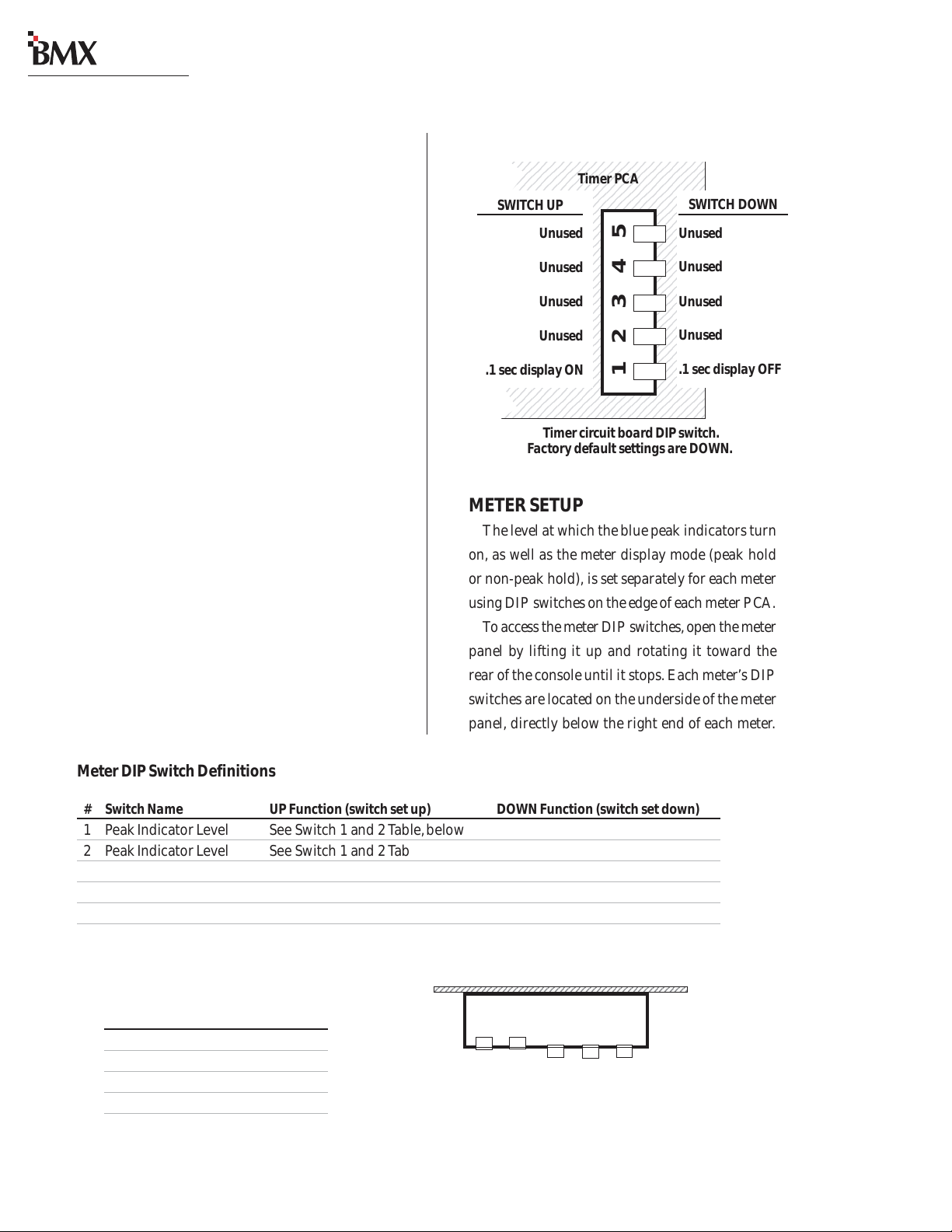
EVENTTIMER
The event timer displays time in minutes, sec-
onds and tenths of seconds.The only timer option
setting is whether to display the tenths of seconds
digit as the timer runs. DS1-1 (a DIP switch on
the timer circuit board, located behind the timer
display),sets whether the tenthsare shown or not.
In the UP position, the tenths of seconds are dis-
played.IntheDOWN position,thefactorydefault,
the tenths do not display while the timer runs.
Note that the tenths of seconds are always shown
when the timer is in the Stop or Hold mode.
Event Timer Option Switches (DS1)
12345678901234567890123456
1
234567890123456789012345
6
1
234567890123456789012345
6
1
234567890123456789012345
6
1
234567890123456789012345
6
1
234567890123456789012345
6
1
234567890123456789012345
6
1
234567890123456789012345
6
1
234567890123456789012345
6
1
234567890123456789012345
6
1
234567890123456789012345
6
1
234567890123456789012345
6
1
234567890123456789012345
6
1
234567890123456789012345
6
1
234567890123456789012345
6
1
234567890123456789012345
6
1
234567890123456789012345
6
1
234567890123456789012345
6
1
234567890123456789012345
6
1
234567890123456789012345
6
1
234567890123456789012345
6
1
234567890123456789012345
6
1
234567890123456789012345
6
1
234567890123456789012345
6
1
234567890123456789012345
6
1
234567890123456789012345
6
1
234567890123456789012345
6
1
234567890123456789012345
6
1
234567890123456789012345
6
1
234567890123456789012345
6
1
234567890123456789012345
6
12345678901234567890123456
Timer circuitboardDIPswitch.
Factory default settings are DOWN.
12345
Timer PCA
SWITCH UP
Unused
Unused
Unused
Unused
.1 sec display ON
SWITCH DOWN
Unused
Unused
Unused
Unused
.1 sec display OFF
METERSETUP
The level atwhich the blue peak indicatorsturn
on, as well as the meter display mode (peak hold
ornon-peak hold), is set separatelyfor each meter
usingDIPswitcheson theedgeofeachmeterPCA.
Toaccessthemeter DIP switches,openthe meter
panel by lifting it up and rotating it toward the
rearofthe console until it stops.Each meter’sDIP
switchesarelocatedon the underside of the meter
panel, directly below the right end of each meter.
MeterDIPSwitchDefinitions
# SwitchName UPFunction(switch set up) DOWNFunction(switchsetdown)
1 Peak Indicator Level See Switch 1 and 2Table,below
2 Peak Indicator Level See Switch 1 and 2Table,below
3 Meter Display Mode * Non-peak hold Peak hold
4 SpareSwitch
5 Termination Switch Set UP for Meter 1 Set DOWN for Meters 2 - 5
* Active only when meters are set to displayAverage and Peak (Session module DIP switch 1 set to Off)
Switch1and2Table
Use these switches to set the level
wherethe Bluepeakindicatorslight.
#1 # 2 Peak Level
DOWN DOWN 0 dB
UP DOWN -2 dB
DOWN UP -4 dB
UP UP -6 dB
Meter Option Switches (DSW2)
MeterPCA
123 45
1234567890123456789012345678901212345678901234567
1234567890123456789012345678901212345678901234567
Switches1,2,3 shown down,
switches4and5 shownup.

2 Installation
di
g
ital
Revision C • 1/04
HARRIS CORPORATION
2-7
WIRE PREPARATION
All BMX
digital
audio and logic wiring termi-
nates in AMP MOD IV receptacle contacts at the
console.Stranded wire of 22 to 26 AWG,with in-
sulation diameters of .040 to .060 inch, can be
used with the AMP MOD IV receptacle contacts.
Follow these steps for audio wire preparation:
1Stripthecableinsulationjacket and foil shield
back 1½" [38.10 mm].
2Remove the foil shield and sleeve the drain
wire with 20 AWG Teflon sleeving. Leave
9/64" [3.57 mm] of the drain wire exposed.
3Cover the cut end of the jacket with 3/4"
[19.05mm]ofheat-shrink tubing.Shrinkthis
tubing,centeredon the jacket cut end,tohold
the drain wire sleeving in place.
4Strip the signal wire insulation back 9/64"
[3.57 mm].
5Crimp the receptacle contact onto the wire
and insulation.
AA
AA
AudioCudioC
udioCudioC
udioCableSableS
ableSableS
ableShieldingNhieldingN
hieldingNhieldingN
hieldingNotot
otot
ote:e:
e:e:
e:To followrecom-
mended grounding procedures, the drain wires
must be sleeved with Teflon sleeving and heat
shrink tubing must cover all cable jacket cut ends
to insulate the shield wiring.
Cabling andWiring
Before installing the console,draw up a facility
wiringplan that lists the console interconnections
withallperipheraldevices.Identifyandcreatetags
for all audio and logic cabling.List each connec-
tion in a master facility wiring logbook to facili-
tate wiring installation, future system wiring
changes,equipment updates,and system trouble-
shooting.
Refer to the module Quick Connection Guides,
on pages 2-16 to 2-57, for information on each
audio and logic connection (including block dia-
grams for each logic interface connector) and on
each module’s setup DIP switches.
REQUIRED CABLES ANDWIRE
The BMX
digital
uses the following types of
cables and wires:
• Analog audio connections require two-
conductor, stranded, insulated, foil-shield
cable using a separate shield drain wire
(equivalenttoBelden8451,9451or8761).
• AES/EBU connections require 110 ohm
two-conductor, stranded, insulated, foil-
shield cable containing a separate shield
drain wire (equivalent to Belden 1800A).
• Logic control cables require stranded, 22
AWG, multiple-conductor, non-shielded,
jacketed cable (equivalent to Belden 9423,
8457 or 9421).The number of conductors
usedisdeterminedbytheapplication.Typi-
cally cables with five and eight wires are
most often used for constructing logic
cables.Even though there are eighteen dis-
tinctsignals on the Logic Interface connec-
tor, only a handful are typically used for
any given application.
AMP MOD IV Receptacle Contacts
9/64”[3.57 mm]
Insulation Barrel
Properly
Crimped Contact
WireBarrel

Revision C • 1/04
HARRIS CORPORATION
2-8
2 Installation
di
g
ital
handles to crimp the contact onto the wire.
The tool handles automatically release and
springopen after the crimp cycleis complete.
Once the contact has been crimped, insert and
lock the contact receptacle into the appropriate
connector housing following the pinout diagrams
found in the Quick Connection Guides on pages
2-16 to 2-57.
A receptacle contact is inserted into the hous-
ing with its locking tab side toward the locking
tab slots on the side of the connector housing. A
slight click can be heard when the contact’s lock-
ing tab springs up into the locking tab slot.
Toremoveacontactfromahousing,thePRE70-
129 Contact Removal Tool (included in the
PRE76-2001toolkit)is required. Insert the tool's
tip into the locking tab slot and press the locking
tab down while lightly pulling on the wire to re-
move the contact from the housing.
Receptacle Contact,
Insertion & Removal Detail
LockingTab
LockingTab Slots
Contact Removal Tool
Logic control cables are fabricated in a similar
manner to the audio wiring.Strip the jacket insu-
lation back 1½" [38.10 mm], sleeve the cut end
with 3/4" [19.05 mm] of shrink tubing and strip
the insulation from each wire 9/64" [3.57 mm].
CRIMPTOOL OPERATION
AratchetingAMPcrimptoolwith contactholder
isincluded.Thetoolcrimpsboth theinsulationand
wire barrels on the AMP MOD IV receptacle con-
tactinonecrimp.To use the ratcheting crimp tool:
1Insertthecontactintothecontact holder with
the barrel openings up.Typically the middle
holder is used (for 20 - 24 AWG wire). Flip
theholderup soitmagneticallylatchesagainst
the crimp tool.The end of the insulation bar-
rel will be about 2 mm from the end of the
die. Close the tool one click (only until the
anvil holds the contact in place,as shown in
the cutaway view,above.)
2Insert the prepped wire into the contact until
the insulation hits the tool’s wire stop. Hold
the wire in place while squeezing the tool
AMP MOD IV
Contact
CrimpTool
CrimpTool — CutawayView
Anvils
Printed
Side of
Crimp
Tool
Insulation Stop
AMPMOD IV
Receptacle
Contact
Die
ContactHolder,
snapped against
CrimpTool
Wire
Audio Wire,ready for insertion into an
AMP MOD IV connector housing
AMPMOD IV
Receptacle Contacts
CableIDTag
3/4”[19.05 mm]
ShrinkTubing
Teflon Sleeving
over drain wire
This manual suits for next models
4
Table of contents
Other Harris Recording Equipment manuals


