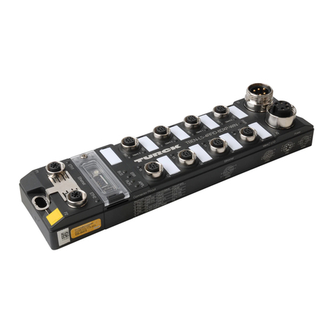
turck TBEN-L5-4RFID-8DXPOPC-UA User manual

Your Global Automation Partner
Instructions for Use
TBEN-L5-4RFID-8DXP-
OPC-UA
Compact RFID Interface

2Hans Turck GmbH & Co. KG | T +49 208 4952-0 | F +49 208 4952-264 | [email protected] | www.turck.com

V02.00 | 2021/11 3
Contents
1 About these instructions................................................................................................................... 7
1.1 Target groups................................................................................................................... 7
1.2 Explanation of symbols used ........................................................................................ 7
1.3 Other documents ............................................................................................................ 7
1.4 Naming convention ........................................................................................................ 7
1.5 Feedback about these instructions.............................................................................. 8
2 Notes on the product......................................................................................................................... 9
2.1 Product identification..................................................................................................... 9
2.2 Scope of delivery ............................................................................................................. 9
2.3 Legal requirements......................................................................................................... 9
2.4 Turck service.....................................................................................................................9
2.5 Exclusion of liability ........................................................................................................ 9
3 For your safety ..................................................................................................................................10
3.1 Intended use...................................................................................................................10
3.2 General safety notes .....................................................................................................10
3.3 Notes on Ex protection.................................................................................................10
3.4 Ex approval requirements for use in Ex area............................................................10
3.5 Notes on UL approval ...................................................................................................11
4 Product description..........................................................................................................................12
4.1 Device overview ............................................................................................................12
4.1.1 Display elements............................................................................................................................12
4.1.2 Operating elements......................................................................................................................12
4.2 Properties and features................................................................................................12
4.3 Operating principle.......................................................................................................13
4.4 Functions and operating modes ................................................................................13
4.4.1 Compatible OPC UA clients........................................................................................................13
4.4.2 Authentication and encryption ................................................................................................13
4.4.3 RFID commands (methods)........................................................................................................14
4.4.4 HF bus mode....................................................................................................................................15
4.4.5 Universal digital channels – functions ...................................................................................16
4.5 Technical accessories....................................................................................................16
5 Installing.............................................................................................................................................17
5.1 Installing the device in Zone 2 and Zone 22 ............................................................17
5.2 Mounting onto a mounting plate ..............................................................................18
5.3 Mounting the device outdoors...................................................................................18
5.4 Grounding the device...................................................................................................19
5.4.1 Equivalent wiring diagram and shielding concept ...........................................................19
5.4.2 Shielding of the fieldbus and I/O level...................................................................................19
5.4.3 Disconnecting the direct grounding of the fieldbus level: removing the
grounding clip.................................................................................................................................20
5.4.4 Grounding the fieldbus level directly: inserting the grounding clip...........................20
5.4.5 Grounding the device – mounting on a mounting plate................................................20

Contents
4Hans Turck GmbH & Co. KG | T +49 208 4952-0 | F +49 208 4952-264 | [email protected] | www.turck.com
6 Connection.........................................................................................................................................21
6.1 Connecting the device in Zone 2 and Zone 22 ........................................................21
6.2 Connecting the modules to Ethernet ........................................................................21
6.3 Connecting the power supply ....................................................................................22
6.4 Connecting RFID read/write devices .........................................................................23
6.4.1 Connecting read/write heads for the HF bus mode..........................................................23
6.5 Connecting digital sensors and actuators................................................................27
7 Commissioning .................................................................................................................................28
7.1 Adjusting network settings.........................................................................................28
7.1.1 Adjusting network settings using switches on the device .............................................28
7.1.2 Adjusting the network settings via the Turck Service Tool ............................................30
7.1.3 Adjusting network settings via the web server ..................................................................32
7.2 Preparing the device for commissioning via the web server ...............................33
7.2.1 Opening the web server and editing the settings.............................................................33
7.2.2 Establishing the connection between the OPC UA server and OPC UA client........37
7.2.3 Validating security certificates ..................................................................................................40
7.2.4 Adapting settings for OPC UA communication – set endpoints..................................42
7.2.5 Setting the OPC UA password...................................................................................................47
7.2.6 Setting up an OPC UA client via an SDK ................................................................................49
8 Setting ................................................................................................................................................50
8.1 Information model – mapping....................................................................................50
8.1.1 RFID channels – mapping in the information model........................................................52
8.1.2 Variable Presence – tag present at read/write head.........................................................58
8.1.3 Setting HF bus mode for OPC UA.............................................................................................58
8.1.4 Digital channels (DXP) – mapping in the information model .......................................63
8.2 Setting RFID interface parameters via the web server...........................................64
8.2.1 Setting RFID channel parameters via the web server.......................................................64
8.2.2 HF applications – selecting the tag type...............................................................................66
8.2.3 HF applications – setting the bridging time (bypass time) ............................................68
8.2.4 Setting digital channels (DXP) parameters via the web server.....................................69
8.2.5 Digital channels – setting switchable VAUX power supply............................................70
8.3 Setting RFID interface parameters via the DTM......................................................72
8.3.1 Connecting the device with the PC.........................................................................................72
8.3.2 Editing parameter data with the DTM – online parameterization...............................75
8.3.3 Evaluating diagnostics with the DTM.....................................................................................76
8.3.4 Reading process input data with the DTM – measured value.......................................77
8.4 Testing the device with demo programs..................................................................78
8.4.1 Testing RFID methods..................................................................................................................79
8.4.2 Testing the reading of UID or EPC ...........................................................................................80
8.5 Setting UHF readers......................................................................................................81
8.5.1 Setting UHF readers via the DTM.............................................................................................81
8.5.2 Setting UHF readers via the web server.................................................................................81
8.5.3 Testing UHF readers via the web server ................................................................................83
9 Operation ...........................................................................................................................................85
9.1 Executing a method and calling data........................................................................85
9.1.1 Example: Reading or writing tags with a specific UID ......................................................86
9.2 HF applications – using the ScanStart method .......................................................92
9.2.1 Executing the ScanStart method by setting the ScanActive variables ......................92
9.3 HF applications – using the ScanStart method in HF bus mode ..........................93
V02.00 | 2021/11 5
9.4 Using HF bus mode .......................................................................................................95
9.4.1 Executing methods in HF bus mode for OPC UA ...............................................................95
9.4.2 Replacing bus-capable read/write heads..............................................................................95
9.4.3 ScanStart in HF bus mode – data query and speed...........................................................95
9.5 Linking sensor signals and RFID methods................................................................96
9.6 LEDs..................................................................................................................................97
9.7 Reading status and diagnostic messages.................................................................99
9.7.1 Read out OPC UA diagnostic messages.................................................................................99
9.7.2 Calling channel and module diagnostic messages in the web server..................... 101
9.8 Reset device (Reset) ................................................................................................... 104
10 Troubleshooting .............................................................................................................................105
10.1 Eliminating parameterization errors ...................................................................... 105
11 Maintenance....................................................................................................................................106
11.1 Executing the firmware update via FDT/DTM ...................................................... 106
11.2 Carry out a firmware update via the web server (from firmware version
2.0.11.0)........................................................................................................................ 111
12 Repair................................................................................................................................................113
12.1 Returning devices....................................................................................................... 113
13 Disposal ............................................................................................................................................113
14 Technical data .................................................................................................................................114
15 Appendix: approvals and markings............................................................................................117
16 Turck subsidiaries – contact information...................................................................................118

Contents
6Hans Turck GmbH & Co. KG | T +49 208 4952-0 | F +49 208 4952-264 | [email protected] | www.turck.com

V02.00 | 2021/11 7
1 About these instructions
These instructions for use describe the structure, functions and the use of the product and will
help you to operate the product as intended. Read these instructions carefully before using the
product. This is to avoid possible damage to persons, property or the device. Retain the instruc-
tions for future use during the service life of the product. If the product is passed on, pass on
these instructions as well.
1.1 Target groups
These instructions are aimed at qualified personnel and must be carefully read by anyone
mounting, commissioning, operating, maintaining, dismantling or disposing of the device.
When operating the device in a hazardous area, the user must have a working knowledge of ex-
plosion protection (EN 60079-14, etc.).
1.2 Explanation of symbols used
The following symbols are used in these instructions:
DANGER
DANGER indicates a dangerous situation with high risk of death or severe injury if
not avoided.
WARNING
WARNING indicates a dangerous situation with medium risk of death or severe in-
jury if not avoided.
CAUTION
CAUTION indicates a dangerous situation of medium risk which may result in minor
or moderate injury if not avoided.
NOTICE
NOTICE indicates a situation which may lead to property damage if not avoided.
NOTE
NOTE indicates tips, recommendations and useful information on specific actions
and facts. The notes simplify your work and help you to avoid additional work.
uCALL TO ACTION
This symbol denotes actions that the user must carry out.
aRESULTS OF ACTION
This symbol denotes relevant results of actions.
1.3 Other documents
Besides this document, the following material can be found on the Internet at www.turck.com:
nData sheet
nInstructions for use
nDeclarations of conformity (current versions)
nApprovals
1.4 Naming convention
Read/write devices are called “read/write heads” for the HF range and “readers” for the UHF
range. Common synonyms for “data carriers” are “tags”, “transponders” and “mobile data
memory”.

About these instructions
Feedback about these instructions
8Hans Turck GmbH & Co. KG | T +49 208 4952-0 | F +49 208 4952-264 | [email protected] | www.turck.com
1.5 Feedback about these instructions
We make every effort to ensure that these instructions are as informative and as clear as pos-
sible. If you have any suggestions for improving the design or if some information is missing in
the document, please send your suggestions to [email protected].

V02.00 | 2021/11 9
2 Notes on the product
2.1 Product identification
These instructions apply to the following compact RFID interfaces:
nTBEN-L5-4RFID-8DXP-OPC-UA
2.2 Scope of delivery
The scope of delivery includes:
nCompact RFID interface
nClosure caps for M12 connectors
nQuick Start Guide
2.3 Legal requirements
The device falls under the following EU directives:
n2014/30/EU (electromagnetic compatibility)
n2011/65/EU (RoHS directive)
n2014/34/EU (ATEX directive)
2.4 Turck service
Turck supports you with your projects, from initial analysis to the commissioning of your applic-
ation. The Turck product database under www.turck.com contains software tools for program-
ming, configuration or commissioning, data sheets and CAD files in numerous export formats.
The contact details of Turck subsidiaries worldwide can be found on p. [}118].
2.5 Exclusion of liability
Only a functioning IT security concept can ensure the security of the data for the entire installa-
tion in which the device is used. Turck does not accept any liability in the event that third
parties access data transferred with the device.

For your safety
Ex approval requirements for use in Ex area
10 Hans Turck GmbH & Co. KG | T +49 208 4952-0 | F +49 208 4952-264 | [email protected] | www.turck.com
3 For your safety
The product is designed according to state-of-the-art technology. However, residual risks still
exist. Observe the following warnings and safety notices to prevent damage to persons and
property. Turck accepts no liability for damage caused by failure to observe these warning and
safety notices.
3.1 Intended use
The TBEN-L5-4RFID-8DXP-OPC block module is an RFID interface for use in the Turck RFID sys-
tem. The Turck RFID system is used for the contactless exchange of data between a tag and a
read/write device in object identification applications. I/O data can also be processed via the di-
gital channels.
The device supports the HF read/write heads from firmware version Vx.90 and UHF readers
from firmware version FW 1.45.
The module can communicate with third-party systems such as ERP systems via an integrated
OPC UA server compliant with the AutoID Companion Specification.
Installation directly in the field is possible thanks to degree of protection IP67. The devices are
suitable for operation in hazardous areas in Zone 2 and Zone 22.
The devices may only be used as described in these instructions. Any other use is not in accord-
ance with the intended use. Turck accepts no liability for any resulting damage.
3.2 General safety notes
nThe device may only be assembled, installed, operated, parameterized and maintained by
professionally-trained personnel.
nThe device may only be used in accordance with applicable national and international regu-
lations, standards and laws.
nThe device meets the EMC requirements for industrial areas. When used in residential areas,
take measures to avoid radio interference.
nChange the default password of the integrated web server after the first login. Turck recom-
mends using a secure password.
3.3 Notes on Ex protection
nWhen operating the device in a hazardous area, the user must have a working knowledge of
explosion protection (EN 60079-14, etc.).
nObserve national and international regulations for explosion protection.
nUse the device only within the permissible operating and ambient conditions (see approval
data and Ex approval specifications).
3.4 Ex approval requirements for use in Ex area
nOnly use the device in an area with no more than pollution degree 2.
nOnly disconnect and connect circuits when no voltage is applied.
nOnly operate the switches if no voltage is present.
nConnect the metal protective cover to the equipotential bonding in the Ex area.
nEnsure impact resistance in accordance with EN IEC 60079-0 – alternative measures:
– Install the device in the TB-SG-L protective housing (available in the set with Ultem
window: ID 100014865) and replace the service window with an Ultem window.
– Install the device in an area offering impact protection (e.g. in robot arm) and attach a
warning: ”DANGER: Only connect and disconnect circuits when no voltage is present.
Do not operate switches when energized.”
nDo not install the device in areas critically exposed to UV light.
nPrevent risks caused by electrostatic charge.
nProtect unused connectors with dummy plugs to ensure protection class IP67.

V02.00 | 2021/11 11
3.5 Notes on UL approval
nUse UL certified PVVA or CYJV cables that are suitable for the current/voltage rating and
have an insulation temperature of at least 90 °C.

Product description
Properties and features
12 Hans Turck GmbH & Co. KG | T +49 208 4952-0 | F +49 208 4952-264 | [email protected] | www.turck.com
4 Product description
The device is designed with a fully encapsulated housing with degree of protection IP67/IP69K.
Four RFID channels are provided for connecting read/write devices. Sensors and actuators can
also be connected via eight digital I/O channels. The digital I/O channels can be configured as
inputs or outputs as required. The terminals for the read/write devices and for digital I/Os are
M12 sockets. Two M12 female connectors are provided for connecting to the Ethernet ports.
4.1 Device overview
218
230.5
C4C5C6C7
6.3
38.8
60.4
C0C1C2C3
24
30.2
X2
X1
P2
P1
Fig.1: Dimensions
4.1.1 Display elements
The device has the following LED indicators:
nPower supply
nGroup and bus errors
nStatus
nDiagnostics
4.1.2 Operating elements
The device is provided with the following operating elements:
nRotary coding switches and DIP switches for adjusting the network settings
nSET button and USB Host port (without function)
4.2 Properties and features
nGlass fiber reinforced housing
nShock and vibration tested
nFully encapsulated module electronics
nDegree of protection IP65/IP67/IP69K
nIntegrated OPC UA server standardized according to the AutoID Companion Specification
nCalling of data via OPC UA clients
nUniversal interface offers interoperability
nSupports security mechanisms and authentication
nFour channels with M12 connection for RFID
nEight universal digital channels as 2A PNP inputs and/or outputs
nMultiple LEDs for status display
nIntegrated Ethernet switch enables line topology
n10 Mbps/100 Mbps transfer rate

V02.00 | 2021/11 13
4.3 Operating principle
The RFID interfaces connect the RFID system with higher-level systems (e.g. ERP systems). The
interfaces are provided with an OPC UA fieldbus interface and fieldbus-independent I/O elec-
tronics with an RFID interface. The interface signals of sensors and actuators can also be pro-
cessed via eight universal digital channels.
The OPC UA interface connects the interface to the higher-level system via Ethernet. Up to four
read/write devices can be connected via the RFID interfaces. During operation, the process data
is exchanged between the higher-level system and RFID system. For this the integrated OPC UA
server of the interface communicates with the OPC UA client of the higher-level system.
4.4 Functions and operating modes
Turck HF read/write heads and Turck UHF readers can be connected to the RFID channels. Par-
allel operation of HF read/write heads and UHF readers on the same device is also possible. The
RFID functionality is defined in accordance with the AutoID Companion Specification and is
available to the user regardless of the platform and manufacturer.
Sensors and actuators can be connected to the universal digital channels. In all, up to four 3-
wire PNP sensors or four PNP DC actuators can be connected per input or output. The max-
imum output current per channel is 2 A. The read data is saved on the OPC UA server of the
module and can be called via OPC UA clients.
4.4.1 Compatible OPC UA clients
The device is compatible with all OPC UA clients that support the method execution and data
model according to the AutoID Companion Specification. For example, the following OPC UA
clients can be used:
nUAExpert – Unified Automation
ndataFeed OPC UA Client – Softing
nOPC Router – Inray
It is also possible to capture RFID data with any OPC UA client by setting variables (ScanStart
and Read), without the client having to support a method execution.
A specific OPC UA client can be programmed with the OPC UA Stack of the OPC Foundation. It
is also possible to use the OPC UA SDKs of other manufacturers. Turck recommends the use of
the “.NET based OPC UA client/server SDK”. The OPC Foundation provides an overview of the
available clients.
4.4.2 Authentication and encryption
For secure communication, the OPC UA interface offers authentication by the signing of certi-
ficates and the encryption of messages on the transport level. The OPC UA server of the device
makes it possible to perform authentication and authorization on the application level by
means of user levels and passwords.

Product description
Functions and operating modes
14 Hans Turck GmbH & Co. KG | T +49 208 4952-0 | F +49 208 4952-264 | [email protected] | www.turck.com
4.4.3 RFID commands (methods)
The RFID functionality is defined in accordance with the AutoID Companion Specification. A
complete description of the methods is provided in the specification. The methods are also de-
scribed in the chapter “Setting”.
The device can perform the following methods and functions:
nScan
nScanStart
nScanStop
nReadTag
nWriteTag
nKillTag (only UHF)
nLockTag
nSetTagPassword
nWriteTagID
Methods and functions in HF bus mode:
nActivateBusHead
nDeactivateBusHead
nDeactivateAllBusHeads
nGetActivatedBusHeads
nGetConnectedBusHeadAddresses
nSetBusHeadAddress

V02.00 | 2021/11 15
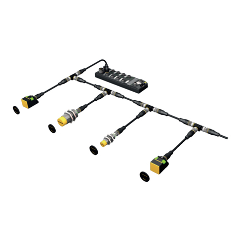
4.4.4 HF bus mode
In HF bus mode up to 32 bus-capable read/write heads per RFID channel can be connected to
the RFID module. An additional power supply may be required depending on the number and
power consumption of connected read/write heads. A power consumption analysis of the con-
nected read/write heads is required in order to determine the additional power supply re-
quired. A tool is provided at www.turck.com/hf-busmodus for calculating the power.
Every connected read/write head supplies a “ Tag present” signal in HF bus mode. HF bus
mode is suitable for static applications and very slow dynamic applications because a com-
mand can only be processed by one read/write head at a time.
The ScanStart method for continuous reading in HF bus mode allows a command to be per-
formed simultaneously at all read/write heads in a bus topology. The logged data is stored in
the ring memory of the module.
TBEN-L…-4RFID-8DXP-…
VT2-FKM5-FKM5-FSM5
RFID connection cable
(e.g. RK4.5T-0.3-RS4.5T/S2503)
TN-M18-H1147/C53
TN-CK40-H1147/C53
TN-M30-H1147/C53
up to 32 per port
Fig.2: HF bus mode setup
The following read/write heads can be used for HF bus mode:
nTN-M18-H1147/C53
nTB-M18-H1147/C53
nTN-M30-H1147/C53
nTB-M30-H1147/C53
nTN-CK40-H1147/C53
nTB-Q08-0.15-RS4.47T/C53
nTN-Q14-0.15-RS4.47T/C53
nTN-Q80-H1147/C53
nTN-R42TC-EX/C53
nTN-R42TC-EX/C65
nTNLR-Q80-H1147/C53
nTNSLR-Q42TWD-H1147/C53
nTNSLR-Q80WD-H1147/C53
HF bus mode supports the HF read/write heads from firmware version Vx.90.
The ScanStart method for continuous reading in HF bus mode supports the HF read/write
heads from firmware version Vx.93.

Product description
Technical accessories
16 Hans Turck GmbH & Co. KG | T +49 208 4952-0 | F +49 208 4952-264 | [email protected] | www.turck.com
4.4.5 Universal digital channels – functions
The device is provided with eight universal digital channels, which can be used as inputs or
outputs according to the application requirements. In all, up to eight 3-wire PNP sensors or
eight PNP DC actuators can be connected per input or output. The maximum output current
per channel is 2A.
4.5 Technical accessories
Accessories for mounting, connecting and parameterizing can be found in product database
under www.turck.com. The accessories are not part of the scope of delivery.

V02.00 | 2021/11 17
5 Installing
5.1 Installing the device in Zone 2 and Zone 22
In Zone 2 and Zone 22, the devices can be used in conjunction with the protective housing set .
DANGER
Potentially explosive atmosphere
Risk of explosion through spark ignition
For use in Zone 2 and Zone 22:
Only install the device if there is no potentially explosive atmosphere present.
Observe requirements for Ex approval.
Unscrew the housing. Use Torx T8 screwdriver.
Replace the service window with the enclosed Ultem window.
Place the device on the base plate of the protective housing and fasten both together on
the mounting plate, see [}18].
Connect the device, see [}21].
Mount and screw the housing cover according to the following figure. The tightening
torque for the Torx T8 screw is 0.5 Nm.
Fig.3: Mounting the device in protection housing TB-SG-L

Mounting
Mounting the device outdoors
18 Hans Turck GmbH & Co. KG | T +49 208 4952-0 | F +49 208 4952-264 | [email protected] | www.turck.com
5.2 Mounting onto a mounting plate
NOTICE
Mounting on uneven surfaces
Device damage due to stresses in the housing
Fix the device on a flat mounting surface.
Use two M6 screws to mount the device.
The device can be screwed onto a flat mounting plate.
Attach the module to the mounting surface with two M6 screws. The maximum tighten-
ing torque for the screws is 1.5 Nm.
Avoid mechanical stresses.
Optional: Ground the device.
218 [5.58]
M6 (2x)
max. 1.5 Nm
Fig.4: Mounting the device onto a mounting plate
5.3 Mounting the device outdoors
The device is UV-resistant according to DIN EN ISO 4892-2. Direct sunlight can cause material
abrasion and color changes. The mechanical and electrical properties of the device are not af-
fected.
To avoid material abrasion and color changes: Protect the device from direct sunlight,
e.g. by using protective shields.

V02.00 | 2021/11 19
5.4 Grounding the device
5.4.1 Equivalent wiring diagram and shielding concept
1 nF
2,2 MΩ
1 nF
2,2 MΩ
X1
C0
C1
C2
C3
P1
X2
C4
C5
C6
C7
P2
4 x 15 nF
Fig.5: TBEN-L5-4RFID-8DXP-OPC-UA – equival-
ent wiring diagram and shielding concept
5.4.2 Shielding of the fieldbus and I/O level
The fieldbus and the I/O level of the modules can be grounded separately.
1
2
3
Fig.6: Grounding clip (1), grounding ring (2) and metal screw (3)
The grounding ring (2) is the module grounding. The shielding of the I/O level is permanently
connected to the module grounding. The module grounding is only connected to the refer-
ence potential of the installation when the module is mounted.
I/O level shielding
In the case of direct mounting on a mounting plate, the module grounding is connected to the
reference potential of the system via the metal screw in the lower mounting hole (3). If module
grounding is not desired, the electrical connection to the reference potential must be interrup-
ted, e.g. by using a plastic screw.
Fieldbus level shielding
The grounding of the fieldbus level can either be connected directly via the grounding clip (1)
or connected and routed indirectly via an RC element to the module grounding. If the ground-
ing is to be routed via an RC element, the grounding clip must be removed.
In the delivery state, the grounding clip is mounted.

Mounting
Grounding the device
20 Hans Turck GmbH & Co. KG | T +49 208 4952-0 | F +49 208 4952-264 | [email protected] | www.turck.com
5.4.3 Disconnecting the direct grounding of the fieldbus level: removing the grounding clip
Use a flat screwdriver to slide the grounding clip forward and remove it.
Fig.7: Use a flat slotted screwdriver to push the grounding clip forwards and remove it.
5.4.4 Grounding the fieldbus level directly: inserting the grounding clip
Place the grounding clip between the fieldbus connectors by using a screwdriver in such
way that the clip contacts the metal housing of the connectors.
The shielding of the fieldbus cables is connected to the grounding clip.
Fig.8: Mounting the grounding clip
5.4.5 Grounding the device – mounting on a mounting plate
For mounting onto a mounting plate: Fix the device with a metal screw through the
lower mounting hole.
aThe module grounding is connected to the reference potential of the installation via the
metal screw.
aWith mounted grounding clip: The shielding of the fieldbus and the module grounding
are connected to the reference potential of the installation.
Table of contents
Other turck Recording Equipment manuals

turck
turck TBEN-L5-4RFID-8DXP-CDS User manual

turck
turck TX700 HMI/PLC Series User manual

turck
turck IMX12-DI 1NAM Series User manual

turck
turck TBEN-L 4RFID-8DXP Series User manual

turck
turck TBEN-S2-2RFID-4DXP User manual

turck
turck TBEN-L Series User manual

turck
turck TX715FB-P3CV01 User manual

turck
turck BL20 User manual

turck
turck TBEN-LL-4RFID-8DXP User manual

turck
turck TBEN-S2-2RFID-4DXP User manual