Transmille 2100 Use and care manual

VERIFICATION AND CALIBRATION GUIDE
2100 / 3200
COMPLETE TESTING
ELECTRICAL TEST EQUIPMENT CALIBRATOR

3200 / 2100 Verification & Calibration Guide
For Use With Calibration Control Panel & Calibration Lead Set
3200 Verification & Calibration Guide.doc
Page 1
Table Of Contents
SAFETY WARNINGS ................................................................................................................................................3
GENERAL..................................................................................................................................................................4
INSTALLING THE 3200 / 2100 CALIBRATION CONTROL PANEL .......................................................................4
CALIBRATING 3200 / 2100 CALIBRATOR - INTRODUCTION...............................................................................5
INSULATION RESISTANCE FUNCTION..................................................................................................................6
CONNECTIONS ..........................................................................................................................................................6
VERIFICATION METHOD..............................................................................................................................................6
VERIFICATION TEST POINTS.......................................................................................................................................6
CONTINUITY RESISTANCE FUNCTION..................................................................................................................7
CONNECTIONS ..........................................................................................................................................................7
VERIFICATION METHOD..............................................................................................................................................7
VERIFICATION TEST POINTS.......................................................................................................................................7
CONTINUITY CURRENT FUNCTION.......................................................................................................................8
CONNECTIONS ..........................................................................................................................................................8
CALIBRATION METHOD...............................................................................................................................................9
VERIFICATION TEST POINTS.......................................................................................................................................9
AC VOLTAGE SOURCE FUNCTION......................................................................................................................10
CONNECTIONS ........................................................................................................................................................10
CALIBRATION METHOD.............................................................................................................................................11
VERIFICATION TEST POINTS.....................................................................................................................................11
LOOP RESISTANCE FUNCTION............................................................................................................................12
CONNECTIONS ........................................................................................................................................................12
CALIBRATION METHOD.............................................................................................................................................14
VERIFICATION TEST POINTS.....................................................................................................................................14
RCD (RESIDUAL CURRENT DEVICE) CURRENT FUNCTION ............................................................................15
CONNECTIONS ........................................................................................................................................................15
CALIBRATION METHOD.............................................................................................................................................16
VERIFICATION TEST POINTS.....................................................................................................................................16
RCD (RESIDUAL CURRENT DEVICE) TRIP TIME FUNCTION............................................................................17
CONNECTIONS ........................................................................................................................................................17
VERIFICATION METHOD............................................................................................................................................18
VERIFICATION TEST POINTS.....................................................................................................................................18
PAT INSULATION RESISTANCE FUNCTION .......................................................................................................19
CONNECTIONS ........................................................................................................................................................19
VERIFICATION METHOD............................................................................................................................................19
VERIFICATION TEST POINTS.....................................................................................................................................19
PAT EARTH BOND RESISTANCE FUNCTION .....................................................................................................20
CONNECTIONS ........................................................................................................................................................20
CALIBRATION METHOD.............................................................................................................................................21
VERIFICATION TEST POINTS.....................................................................................................................................21

3200 / 2100 Verification & Calibration Guide
For Use With Calibration Control Panel & Calibration Lead Set
3200 Verification & Calibration Guide.doc
Page 2
PAT EARTH BOND CURRENT FUNCTION...........................................................................................................22
CONNECTIONS ........................................................................................................................................................22
CALIBRATION METHOD.............................................................................................................................................23
VERIFICATION TEST POINTS.....................................................................................................................................23
PAT LOAD FUNCTION............................................................................................................................................24
CONNECTIONS ........................................................................................................................................................24
VERIFICATION METHOD............................................................................................................................................25
VERIFICATION TEST POINTS.....................................................................................................................................25
PAT LEAKAGE CURRENT FUNCTION .................................................................................................................26
CONNECTIONS ........................................................................................................................................................26
VERIFICATION METHOD............................................................................................................................................27
VERIFICATION TEST POINTS.....................................................................................................................................27
3200 / 2100 Verification Sheets Appendix A
3200 / 2100 Extended Specifications Appendix B

3200 / 2100 Verification & Calibration Guide
For Use With Calibration Control Panel & Calibration Lead Set
3200 Verification & Calibration Guide.doc
Page 3
SAFETY WARNINGS
HIGH VOLTAGES
CONNECTIONS TO LINE
THIS VERIFICATION AND CALIBRATION GUIDE
INVOLVES CONNECTIONS TO LINE AND
MEASUREMENT OF HIGH VOLTAGES
FOR THIS REASON VERIFICATION AND
CALIBRATION SHOULD ONLY BE UNDERTAKEN
BY QUALIFIED PERSONNEL
THIS VERIFICATION AND CALIBRATION KIT IS
PROVIDED ‘AS-IS’ AND TRANSMILLE SHALL
NOT BE LIABLE FOR ANY INCIDENTAL, INDIRECT,
SPECIAL OR CONSEQUENTIAL DAMAGES
OR LOSS AS A RESULT OF USING THIS GUIDE OR
VERIFICATION AND CALIBRATION LEAD SET.
3200 / 2100 Verification & Calibration Guide
For Use With Calibration Control Panel & Calibration Lead Set
3200 Verification & Calibration Guide.doc
Page 4
General
The steps detailed below will allow adjustment of a 3200 / 2100 Electrical Test Equipment Calibrator.
This requires the use of the 3200 / 2100/3200 Calibration control Panel program supplied and the 3200 / 2100
calibration lead set kit supplied by Transmille.
Installing the 3200 / 2100 calibration control panel
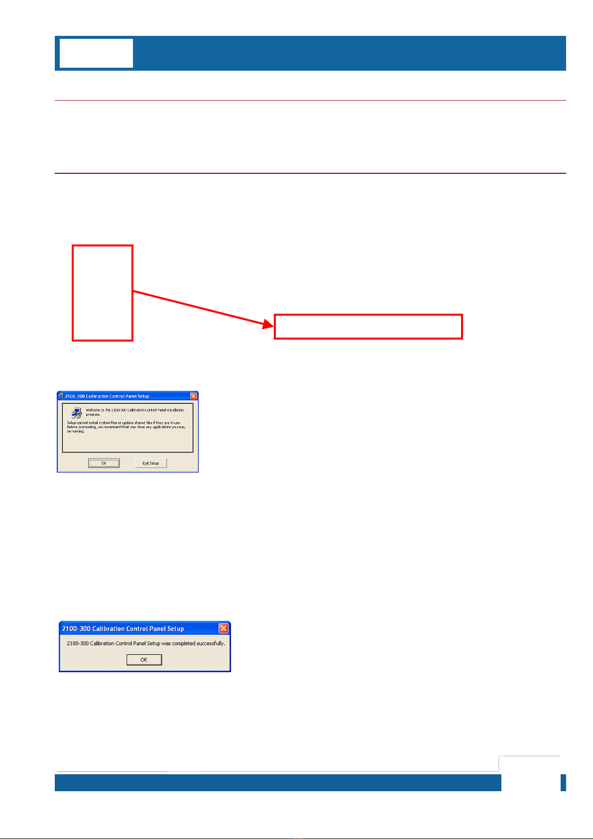
To install the 3200 / 2100 Calibration Control Panel, insert the supplied CD – this should autorun.
If the CD does not autorun, select START -> RUN -> AUTOCHECK.BAT
Click OK to proceed
Click button to begin install
Click OK to complete installation

3200 / 2100 Verification & Calibration Guide
For Use With Calibration Control Panel & Calibration Lead Set
3200 Verification & Calibration Guide.doc
Page 5
Calibrating 3200 / 2100 calibrator - Introduction
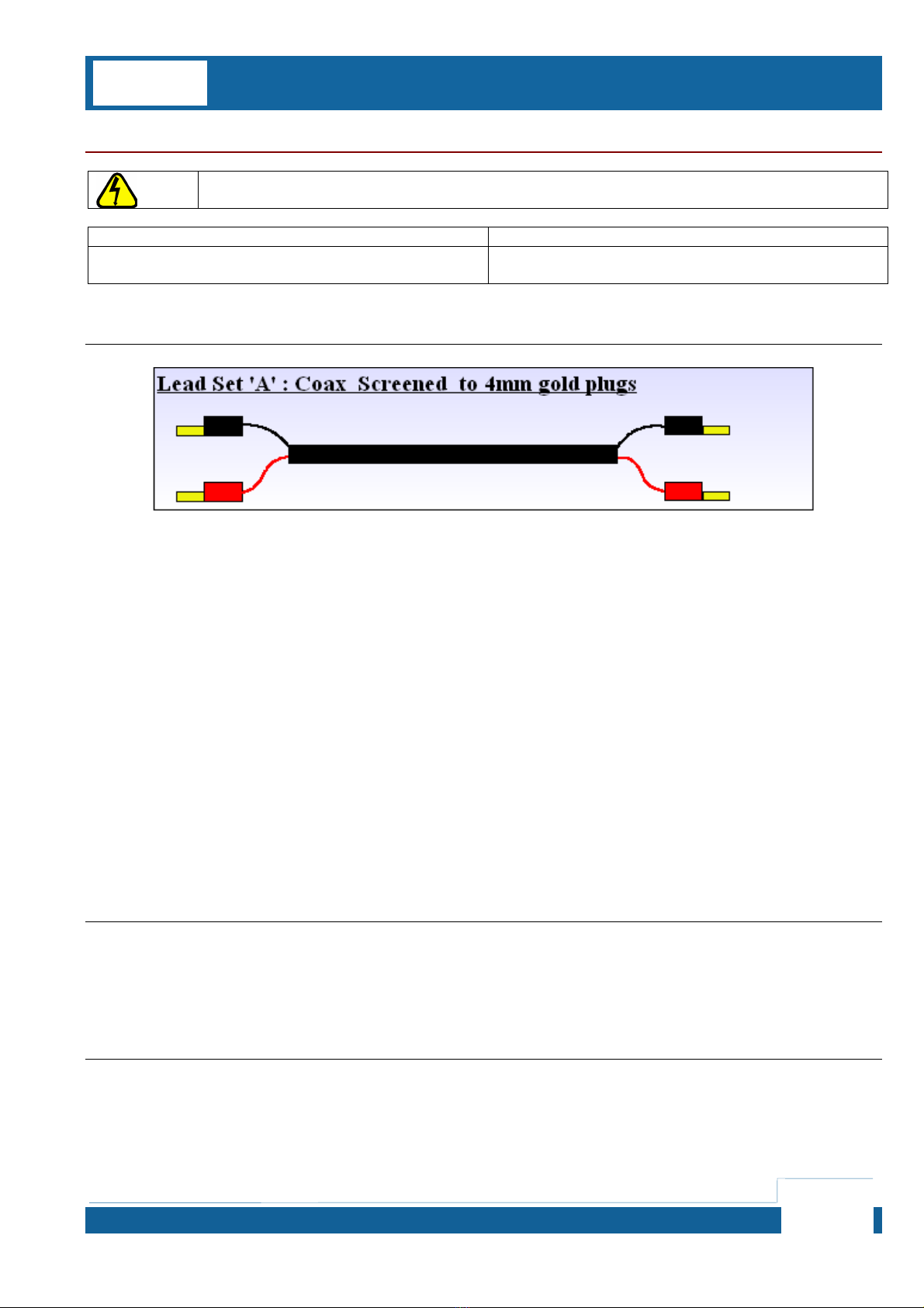
The 3200 / 2100 Calibration kit comprises of a set of test leads as follows :
In addition a performance verification sheet is provided –
this allows the 3200 / 2100 to be compared against manufacturers specifications.
3200 / 2100 Verification & Calibration Guide
For Use With Calibration Control Panel & Calibration Lead Set
3200 Verification & Calibration Guide.doc
Page 6
Insulation Resistance Function
VERIFICATION AND CALIBRATION PROCEDURES ARE FOR USE BY QUALIFIED TECHNICIANS ONLY –
OBSERVE ALL PRECAUTIONS DURING CONNECTION AND MEASUREMENT OF LINE HIGH VOLTAGES
Equipment Required Comments
Resistance meter Capable of measuring 2GOhm
(10GOhm if 10G Option fitted)
Connections
Verification Method
1. Connect 3200 / 2100 to meter as per diagram using LEAD SET A
2. Select Insulation resistance mode and test points as per verification sheet using the 3200 / 2100 front panel and
record measurement obtained using 2-wire connection.
Verification Test Points
See Performance Verifications Sheet Page 1 & 2

3200 / 2100 Verification & Calibration Guide
For Use With Calibration Control Panel & Calibration Lead Set
3200 Verification & Calibration Guide.doc
Page 7
Continuity Resistance Function
VERIFICATION AND CALIBRATION PROCEDURES ARE FOR USE BY QUALIFIED TECHNICIANS ONLY –
OBSERVE ALL PRECAUTIONS DURING CONNECTION AND MEASUREMENT OF LINE HIGH VOLTAGES
Equipment Required Comments
Resistance meter Capable of measuring 100mOhm to 1kOhm
4-Wire mode
Connections
Verification Method
1. Connect 3200 / 2100 to meter as per diagram using LEAD SET A and LEAD SET B
2. Select test point as per verification sheet using the 3200 / 2100 front panel and record measurement obtained
using 4-wire connection.
Verification Test Points
See Performance Verifications Sheet Page 2 & 3

3200 / 2100 Verification & Calibration Guide
For Use With Calibration Control Panel & Calibration Lead Set
3200 Verification & Calibration Guide.doc
Page 8
Continuity Current Function
VERIFICATION AND CALIBRATION PROCEDURES ARE FOR USE BY QUALIFIED TECHNICIANS ONLY –
OBSERVE ALL PRECAUTIONS DURING CONNECTION AND MEASUREMENT OF LINE HIGH VOLTAGES
Equipment Required Comments
DC Current Source
eg. Multi Product Calibrator Capable of sourcing 100mA DC
Connections

3200 / 2100 Verification & Calibration Guide
For Use With Calibration Control Panel & Calibration Lead Set
3200 Verification & Calibration Guide.doc
Page 9
Calibration Method
1. Connect 3200 / 2100 to meter as per diagram using LEAD SET A
2. Select continuity test current mode on 3200 / 2100 CCP
this will set the 3200 / 2100 to 1 Ohm output
3. Set 0mA DC output from current source
4. Adjust ZERO OFFSET using CCP software
5. Set 100mA DC output from current source
6. Adjust MULTIPLIER (FULL SCALE) using CCP software
Verification Test Points
See Performance Verifications Sheet Page 4
ZERO OFFSET ADJUST
A
djust cal factor using up/down buttons – note using the up/down button
automatically sends cal factor to calibrator, the send button is needed
only if a cal factor is manually typed into the cal factor value box.
MULTIPLIER ADJUST
A
djust cal factor using up/down buttons – note using the up/down button
automatically sends cal factor to calibrator, the send button is needed
only if a cal factor is manually typed into the cal factor value box.

3200 / 2100 Verification & Calibration Guide
For Use With Calibration Control Panel & Calibration Lead Set
3200 Verification & Calibration Guide.doc
Page 10
AC Voltage Source Function
VERIFICATION AND CALIBRATION PROCEDURES ARE FOR USE BY QUALIFIED TECHNICIANS ONLY –
OBSERVE ALL PRECAUTIONS DURING CONNECTION AND MEASUREMENT OF LINE HIGH VOLTAGES
Equipment Required Comments
AC Voltage meter Capable of measuring up to 400V AC
Connections
3200 / 2100 Verification & Calibration Guide
For Use With Calibration Control Panel & Calibration Lead Set
3200 Verification & Calibration Guide.doc
Page 11
Calibration Method
1. Connect 3200 / 2100 to meter as per diagram using LEAD SET A
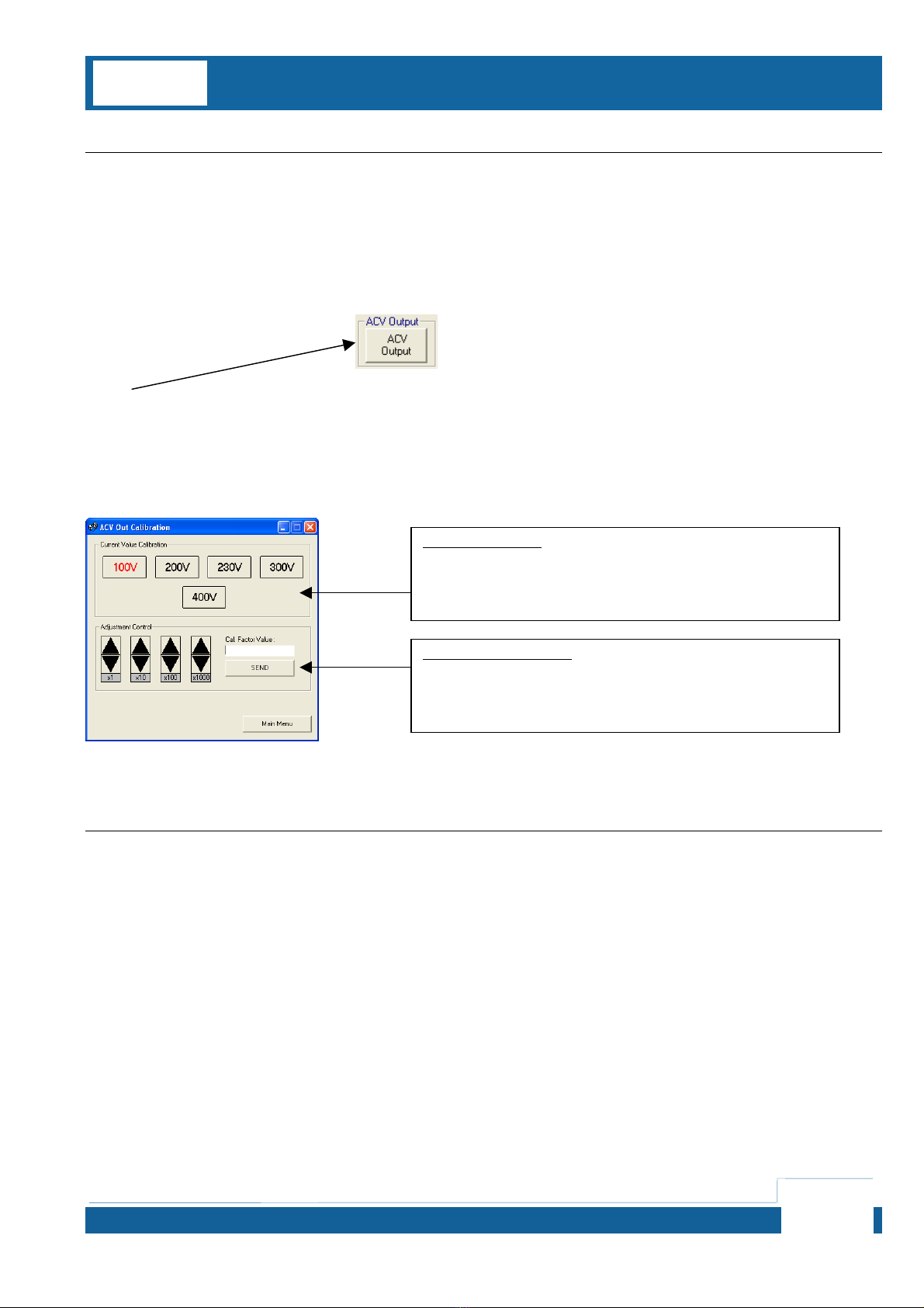
2. Select ACV Output mode on 3200 / 2100 CCP - this will set the 3200 / 2100 to 100V Output initially
3. Adjust cal factor using CCP software adjustment control
4. Select 200V, 230V, 300V and 400V ranges in turn and adjust each range in turn
Verification Test Points
See Performance Verifications Sheet Page 4
RANGE SELECTION
Select range to be calibrated here
ADJUSTMENT CONTROL
A
djust cal factor using up/down buttons – note using the up/down button
automatically sends cal factor to calibrator, the send button is needed
only if a cal factor is manually typed into the cal factor value box.
3200 / 2100 Verification & Calibration Guide
For Use With Calibration Control Panel & Calibration Lead Set
3200 Verification & Calibration Guide.doc
Page 12
Loop Resistance Function
VERIFICATION AND CALIBRATION PROCEDURES ARE FOR USE BY QUALIFIED TECHNICIANS ONLY –
OBSERVE ALL PRECAUTIONS DURING CONNECTION AND MEASUREMENT OF LINE HIGH VOLTAGES
Equipment Required Comments
DC Voltage meter
DC Current Source Capable of sourcing up to1A DC
Connections
NOTES FOR USE WITH LEAD SET ‘C’
Set C1
COMMON SET OF TEST LEADS (RED & BLACK LEADS) IS A COMMON SET FOR USE WITH ANY TYPE OF
2100 / 3200 CALIBRATOR.
DEPENDING ON THE CONFIGURATION OF THE 2100 / 3200 CALIBRATOR THE SECOND LEAD SHOULD
BE EITHER :
Set C2
LEAD MARKED FOR ‘NORMAL’ CONFIGURATION EARTH-EARTH
OR
Set C3
LEAD MARKED FOR ‘EARTH-NEUTRAL’ (NO TRIP) CONFIGURATION –
NOTE THESE CALIBRATORS WILL BE MARKED AS EARTH-NEUTRAL ON THE REAR PANEL
OPTION LABEL IF CONFIGURED THIS WAY.

3200 / 2100 Verification & Calibration Guide
For Use With Calibration Control Panel & Calibration Lead Set
3200 Verification & Calibration Guide.doc
Page 13
3200 / 2100 Verification & Calibration Guide
For Use With Calibration Control Panel & Calibration Lead Set
3200 Verification & Calibration Guide.doc
Page 14
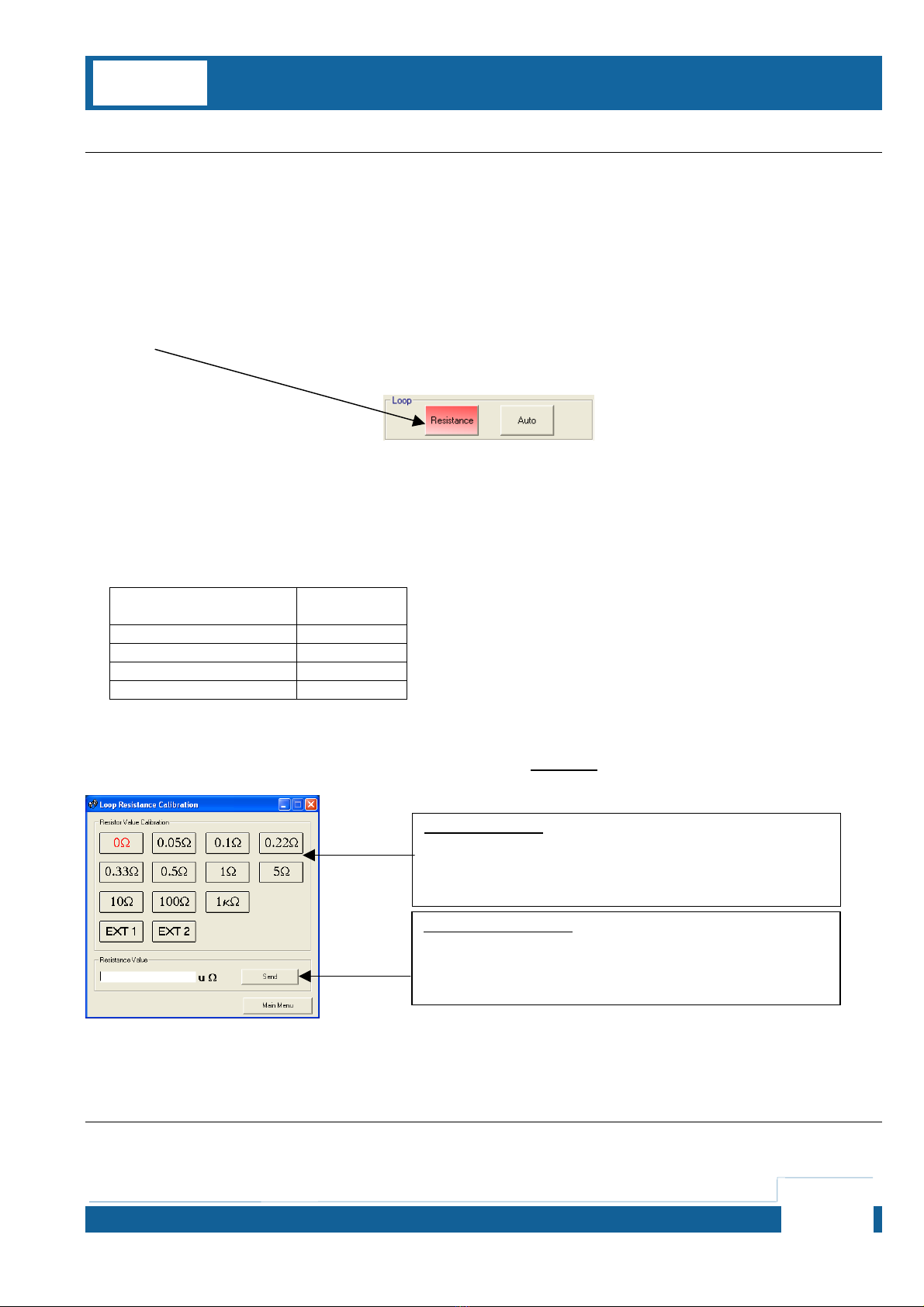
Calibration Method
1. Connect 3200 / 2100 to meter as per diagram using LEAD SET C
2. Select LOOP function on 3200 / 2100 and select MANUAL – type in 0.001 then press enter to reset the line
impedance compensation to ZERO before calibrating the loop resistance values.
3. Select Loop Resistance mode on 3200 / 2100 CCP
this will set the 3200 / 2100 to 0Ohms Output initially
4. Set the current source to the current as specified in the table below and measure voltage drop
Loop Resistance
Value Current
Setting
1 kOhm 1mA
100 Ohms 10mA
10 Ohms 100mA
< 5 Ohms 1A
5. Calculate resistance value using Ohms Law (V/I = R)
6. Enter calculated resistance into resistance value box on CCP in uOhms and click SEND
7. Repeat steps 4 to 6 for all resistance values.
Verification Test Points
See Performance Verifications Sheet Page 5
RANGE SELECTION
Select range to be calibrated here
ADJUSTMENT CONTROL
A
djust cal factor using up/down buttons – note using the up/down button
automatically sends cal factor to calibrator, the send button is needed
only if a cal factor is manually typed into the cal factor value box.

3200 / 2100 Verification & Calibration Guide
For Use With Calibration Control Panel & Calibration Lead Set
3200 Verification & Calibration Guide.doc
Page 15
RCD (Residual Current Device) Current Function
VERIFICATION AND CALIBRATION PROCEDURES ARE FOR USE BY QUALIFIED TECHNICIANS ONLY –
OBSERVE ALL PRECAUTIONS DURING CONNECTION AND MEASUREMENT OF LINE HIGH VOLTAGES
Equipment Required Comments
AC Current Source Capable of sourcing up to 3A AC 50Hz
Connections

3200 / 2100 Verification & Calibration Guide
For Use With Calibration Control Panel & Calibration Lead Set
3200 Verification & Calibration Guide.doc
Page 16
Calibration Method
1. Connect 3200 / 2100 to meter as per diagram using LEAD SET D
2. Select RCD Current mode on 3200 / 2100 CCP
this will set the 3200 / 2100 to 10mA Range in calibration mode (continuous reading)
3. Set the current source to the current range full scale
4. Adjust cal factor using CCP software adjustment control
5. Repeat process for each RCD current range
Verification Test Points
See Performance Verifications Sheet Page 6
RANGE SELECTION
Select range to be calibrated here
ADJUSTMENT CONTROL
A
djust cal factor using up/down buttons – note using the up/down button
automatically sends cal factor to calibrator, the send button is needed
only if a cal factor is manually typed into the cal factor value box.

3200 / 2100 Verification & Calibration Guide
For Use With Calibration Control Panel & Calibration Lead Set
3200 Verification & Calibration Guide.doc
Page 17
RCD (Residual Current Device) Trip Time Function
VERIFICATION AND CALIBRATION PROCEDURES ARE FOR USE BY QUALIFIED TECHNICIANS ONLY –
OBSERVE ALL PRECAUTIONS DURING CONNECTION AND MEASUREMENT OF LINE HIGH VOLTAGES
Equipment Required Comments
Digital Storage Oscilloscope
RCD & oscilloscope Trigger Box Supplied with calibration kit
Connections

3200 / 2100 Verification & Calibration Guide
For Use With Calibration Control Panel & Calibration Lead Set
3200 Verification & Calibration Guide.doc
Page 18
Verification Method
1. Connect 3200 / 2100 to meter as per diagram using RCD & OSCILLOSCOPE TRIGGER BOX
2. Select RCD Function on 3200 / 2100 – set 10mA / 40ms trip current / time
3. Adjust setting on oscilloscope for storage mode and to use external trigger input
Set 5V/Div Amplitude, 5ms Timebase.
Select external trigger and single shot storage mode as to view waveform as shown in screenshot below.
Adjust to trigger oscilloscope on a 5V rising edge.
4. Press the TEST soft key on the 3200 / 2100 to begin the test
If the button is pressed at the wrong part of the mains cycle an obviously incorrect time period will result.
Simply reset the oscilloscope / 3200 / 2100 and press button again to retest.
5. Read the timing from the oscilloscope – target value is 40ms ± 0.7ms
Verification Test Points
See Performance Verification Sheet Page 6
3200 / 2100 Verification & Calibration Guide
For Use With Calibration Control Panel & Calibration Lead Set
3200 Verification & Calibration Guide.doc
Page 19
PAT Insulation Resistance Function
VERIFICATION AND CALIBRATION PROCEDURES ARE FOR USE BY QUALIFIED TECHNICIANS ONLY –
OBSERVE ALL PRECAUTIONS DURING CONNECTION AND MEASUREMENT OF LINE HIGH VOLTAGES
Equipment Required Comments
Resistance Meter Capable of measuring up to 1kOhm
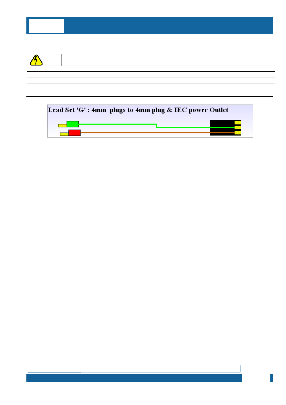
Connections
Verification Method
1. Connect 3200 / 2100 to meter as per diagram using LEAD SET G
2. Select PAT Insulation Resistance mode and test points as per verification sheet using the 3200 / 2100 front
panel and record measurement obtained using 2-wire connection.
Verification Test Points
See Performance Verifications Sheet Page 6
Other manuals for 2100
1
This manual suits for next models
1
Table of contents
Other Transmille Test Equipment manuals

Transmille
Transmille 5080 User manual

Transmille
Transmille 4610M Use and care manual

Transmille
Transmille 3000 Series Use and care manual

Transmille
Transmille 3000 Series User manual

Transmille
Transmille 1000 Series User manual

Transmille
Transmille 9000 Series User manual

Transmille
Transmille 1000 Series Use and care manual

Transmille
Transmille 4610M User manual

Transmille
Transmille 2100 User manual

Transmille
Transmille 3200B User manual


