HART L20222 User manual

Operating Instructions
L20222
Temperature transmitter
with HART® protocol
BA02278O/09/EN/01.22-00
71600050
2022-11-16
Valid as of version
01.01 (device version)


L20222 Table of contents
3
Table of contents
1 About this document ................ 4
1.1 Document function ..................... 4
1.2 Safety instructions ...................... 4
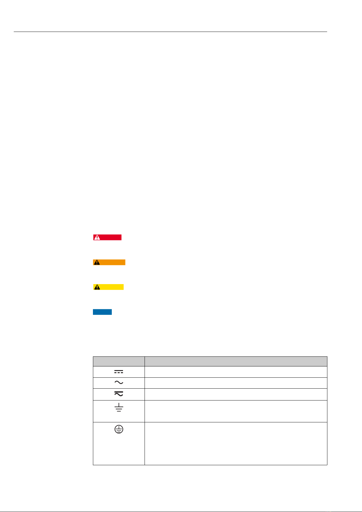
1.3 Symbols used .......................... 4
1.4 Tool symbols .......................... 5
1.5 Registered trademarks ................... 6
2 Basic safety instructions ............ 7
2.1 Requirements for the personnel ............ 7
2.2 Intended use .......................... 7
2.3 Operational safety ...................... 7
3 Incoming acceptance and product
identification ....................... 8
3.1 Incoming acceptance .................... 8
3.2 Nameplate ............................ 8
3.3 Name and address of manufacturer ......... 9
3.4 Scope of delivery ....................... 9
3.5 Certificates and approvals ................ 9
3.6 Storage and transport .................. 10
4 Mounting ......................... 11
4.1 Mounting requirements ................. 11
4.2 Mounting the device ................... 11
4.3 Post-installation check .................. 16
5 Electrical connection .............. 17
5.1 Connecting requirements ................ 17
5.2 Quick wiring guide ..................... 18
5.3 Connecting the sensor cables ............. 18
5.4 Connecting the transmitter .............. 19
5.5 Special connection instructions ............ 20
5.6 Ensuring the degree of protection .......... 21
5.7 Post-connection check .................. 21
6 Operation options ................. 22
6.1 Overview of operation options ............ 22
6.2 Structure and function of the operating
menu .............................. 25
6.3 Access to the operating menu via the PC
operating tool ........................ 27
6.4 Access to the operating menu via the
Wireless Field Device Configurator App ..... 28
7 System integration ................ 29
7.1 Overview of device description files ......... 29
7.2 Measured variables via HART protocol ...... 29
7.3 Supported HART® commands ............. 29
8 Commissioning .................... 32
8.1 Post-installation check .................. 32
8.2 Switching on the transmitter ............. 32
8.3 Protecting settings from unauthorized access .32
9 Diagnostics and troubleshooting ... 34
9.1 General troubleshooting ................. 34
9.2 Diagnostic information on local display ...... 36
9.3 Diagnostic information via communication
interface ............................ 36
9.4 Diagnostic list ........................ 37
9.5 Event logbook ........................ 37
9.6 Overview of diagnostic events ............. 37
10 Maintenance ...................... 39
11 Repair ............................ 39
11.1 General information ................... 39
11.2 Spare parts .......................... 40
11.3 Return .............................. 40
11.4 Disposal ............................ 40
12 Accessories ....................... 40
13 Technical data .................... 41
13.1 Input ............................... 41
13.2 Output ............................. 42
13.3 Power supply ......................... 43
13.4 Performance characteristics .............. 44
13.5 Environment ......................... 51
13.6 Mechanical construction ................ 52
13.7 Certificates and approvals ............... 54
14 Operating menu and parameter
description ........................ 56
14.1 Menu: Diagnostics ..................... 60
14.2 Menu: Application ..................... 66
14.3 Menu: System ........................ 76
Index .................................. 92

About this document L20222
4
1 About this document
1.1 Document function
These Operating Instructions contain all the information required in the various life cycle
phases of the device: from product identification, incoming acceptance and storage, to
installation, connection, operation and commissioning, through to troubleshooting,
maintenance and disposal.
1.2 Safety instructions
When using in hazardous areas, compliance with national regulations is mandatory.
Separate Ex-specific documentation is provided for measuring systems that are used in
hazardous areas. This documentation is an integral part of these Operating Instructions.
The installation specifications, connection data and safety instructions it contains must be
strictly observed! Make sure that you use the right Ex-specific documentation for the right
device with approval for use in hazardous areas!
1.3 Symbols used
1.3.1 Safety symbols
DANGER
This symbol alerts you to a dangerous situation. Failure to avoid this situation will result in
serious or fatal injury.
WARNING
This symbol alerts you to a dangerous situation. Failure to avoid this situation can result in
serious or fatal injury.
CAUTION
This symbol alerts you to a dangerous situation. Failure to avoid this situation can result in
minor or medium injury.
NOTICE
This symbol contains information on procedures and other facts which do not result in
personal injury.
1.3.2 Electrical symbols
Symbol Meaning
Direct current
Alternating current
Direct current and alternating current
Ground connection
A grounded terminal which, as far as the operator is concerned, is grounded via a
grounding system.
Potential equalization connection (PE: protective earth)
Ground terminals that must be connected to ground prior to establishing any other
connections.
The ground terminals are located on the interior and exterior of the device:
• Interior ground terminal: potential equalization is connected to the supply network.
• Exterior ground terminal: device is connected to the plant grounding system.

L20222 About this document
5
1.3.3 Symbols for certain types of information
Symbol Meaning
Permitted
Procedures, processes or actions that are permitted.
Preferred
Procedures, processes or actions that are preferred.
Forbidden
Procedures, processes or actions that are forbidden.
Tip
Indicates additional information.
Reference to documentation
A
Reference to page
Reference to graphic
Notice or individual step to be observed
1.
,
2.
,
3.
… Series of steps
Result of a step
Help in the event of a problem
Visual inspection
1.3.4 Symbols in graphics
Symbol Meaning Symbol Meaning
1, 2, 3,... Item numbers
1.
,
2.
,
3.
… Series of steps
A, B, C, ... Views A-A, B-B, C-C, ... Sections
-
Hazardous area
.
Safe area (non-hazardous area)
1.4 Tool symbols
Symbol Meaning
A0011220
Flat-blade screwdriver
A0011219
Phillips head screwdriver
A0011221
Allen key
A0011222
Open-ended wrench
A0013442
Torx screwdriver

About this document L20222
6
1.5 Registered trademarks
Bluetooth®
The Bluetooth® word mark and logos are registered trademarks owned by Bluetooth SIG,
Inc. and any use of such marks is under license. Other trademarks and trade names are
those of their respective owners.
HART®
Registered trademark of the FieldComm Group, Austin, Texas, USA

L20222 Basic safety instructions
7
2 Basic safety instructions
2.1 Requirements for the personnel
The personnel for installation, commissioning, diagnostics and maintenance must fulfill
the following requirements:
‣Trained, qualified specialists: must have a relevant qualification for this specific
function and task
‣Are authorized by the plant owner/operator
‣Are familiar with federal/national regulations
‣They must have read and understood the instructions in the manual, supplementary
documentation and certificates (depending on the application) prior to starting work
‣Follow instructions and comply with basic conditions
The operating personnel must fulfill the following requirements:
‣Must be suitably trained and authorized by the plant operator to meet the
requirements of the task
‣Follow the instructions in this manual
2.2 Intended use
The device is a universal and user-configurable temperature transmitter with one sensor
input for resistance thermometers (RTD), thermocouples (TC), resistance and voltage
transmitters. The head transmitter version of the device is intended for mounting in a
terminal head (flat face) as per DIN EN 50446. It is also possible to mount the device on a
DIN rail using the optional DIN rail clip. The device is also optionally available in a version
suitable for DIN rail mounting as per IEC 60715 (TH35).
If the device is used in a manner not specified by the manufacturer, the protection
provided by the device may be impaired.
The manufacturer is not liable for damage caused by improper or non-intended use.
2.3 Operational safety
‣Operate the device only if it is in proper technical condition, free from errors and faults.
‣The operator is responsible for the interference-free operation of the device.
Hazardous area
To eliminate a danger for persons or for the facility when the device is used in the
hazardous area (e.g. explosion protection or safety equipment):
‣Based on the technical data on the nameplate, check whether the ordered device is
permitted for the intended use in the hazardous area. The nameplate can be found on
the side of the transmitter housing.
‣Observe the specifications in the separate supplementary documentation that is an
integral part of these instructions.
Electromagnetic compatibility
The measuring system complies with the general safety requirements as per EN 61010-1,
the EMC requirements as per the IEC/EN 61326 series and the NAMUR recommendations
NE 21.
NOTICE
‣The device must only be powered by a power unit that operates using an energy-limited
electric circuit according to UL/EN/IEC 61010-1, Section 9.4 and the requirements in
Table 18.

Incoming acceptance and product identification L20222
8
3 Incoming acceptance and product
identification
3.1 Incoming acceptance
1. Unpack the temperature transmitter carefully. Is the packaging or content free from
damage?
Damaged components must not be installed as the manufacturer can otherwise
not guarantee compliance with the original safety requirements or the material
resistance, and can therefore not be held responsible for any resulting damage.
2. Is the delivery complete or is anything missing? Check the scope of delivery against
your order.
3. Does the nameplate match the ordering information on the delivery note?
4. Are the technical documentation and all other necessary documents provided? If
applicable: are the Safety Instructions (e.g. XA) for hazardous areas provided?
3.2 Nameplate
The right device?
Compare and check the data on the nameplate of the device against the requirements of
the measuring point:
11-42V 012345678910
xx.yy.zz
Made in Germany 202x, Endress+Hauser Wetzer D-47484 Nesselwang
Ser.no.:
FW:
Input:
Dev.Rev: x
Ext. ord. cd.:
XXXXXXXXXXXXX#
12
4
3
Universal Temperature
Transmitter HART
6
5
A0051223
1 Nameplate of the head transmitter (example)
1 Power supply, current consumption, serial number, device revision and hardware version
2 Radio approval (Bluetooth) and serial number
3 Approvals with symbols
4 Approval data and order code
5 Device name
6 Characters for tag name (TAG)

L20222 Incoming acceptance and product identification
9
2
Universal Temperature
Transmitter HART
Made in Germany 202x, Endress+Hauser Wetzer D-47484 Nesselwang
3
45
6
1
7
A0051224
2 Nameplate of DIN rail transmitter (example)
1 Device name
2 Characters for tag name (TAG)
3 Approval data
4 Power supply and current consumption, output
5 Radio approval (Bluetooth)
6 Approvals with symbols
7 Serial number, device revision, order code
3.3 Name and address of manufacturer
Name of manufacturer: Endress+Hauser Wetzer GmbH + Co. KG
Address of manufacturer: Obere Wank 1, D-87484 Nesselwang
3.4 Scope of delivery
The scope of delivery of the device comprises:
• Temperature transmitter
• Mounting material (optional for head transmitter)
• Printed copy of the Brief Operating Instructions in English
• Additional documentation for devices which are suitable for use in the hazardous area
(ATEX, FM, CSA).
3.5 Certificates and approvals
The device left the factory in a safe operating condition. The device complies with the
requirements of the standards EN 61010-1 "Safety Requirements for Electrical Equipment
for Measurement, Control, and Laboratory Use" and with the EMC requirements as per the
IEC/EN 61326 series.
3.5.1 CE/EAC mark, Declaration of Conformity
The device meets the legal requirements of the EU/EEU guidelines. The manufacturer
confirms that the device is compliant with the relevant guidelines by applying the CE/EAC
mark.

Incoming acceptance and product identification L20222
10
3.5.2 HART® protocol certification
The temperature transmitter is registered by the HART® FieldComm Group. The device
meets the requirements of the HART® Communication Protocol Specifications, Revision 7
(HCF 7.6).
3.6 Storage and transport
Storage temperature
• Head transmitter: –50 to +100 °C (–58 to +212 °F)
• DIN rail device: –50 to +100 °C (–58 to +212 °F)
• Humidity: (device-specific): max. rel. humidity: 95 % as per IEC 60068-2-30
Pack the device for storage and transportation in such a way that it is reliably
protected against impact and external influences. The original packaging offers the
best protection.
Avoid the following environmental influences during storage:
• Direct sunlight
• Vibration
• Aggressive media

L20222 Mounting
11
4 Mounting
4.1 Mounting requirements
4.1.1 Dimensions
The dimensions of the device are provided in the "Technical data" section .
4.1.2 Mounting location
• Head transmitter:
• In the terminal head, flat face, as per DIN EN 50446, direct mounting on insert with
cable entry (middle hole 7 mm)
• In the field housing, separated from the process
• DIN rail transmitter:
Designed for mounting on a DIN rail (IEC 60715 TH35).
It is also possible to mount the head transmitter on a DIN rail as per IEC 60715 using
the DIN rail clip accessory.
Information about the conditions (such as the ambient temperature, degree of protection,
climate class etc.) that must be present at the installation point so that the device can be
mounted correctly is provided in the "Technical data" section → 51.
When using in hazardous areas, the limit values of the certificates and approvals must be
observed (see Ex Safety Instructions).
NOTICE
When using a DIN rail transmitter with a thermocouple/mV measurement, increased
measurement deviations may occur depending on the installation situation and
ambient conditions.
‣If the DIN rail transmitter is mounted on the DIN rail without any adjacent devices, this
may result in deviations of up to ± 1.34 °C. If the DIN rail transmitter is mounted in
series between other DIN rail devices (reference operating conditions: 24 V, 12 mA),
deviations of up to + 2.94 °C may occur.
4.2 Mounting the device
A Phillips head screwdriver is required to mount the head transmitter:
• Maximum torque for securing screws = 1 Nm (¾ foot-pound), screwdriver: Pozidriv Z2
• Maximum torque for screw terminals = 0.35 Nm (¼ foot-pound), screwdriver: Pozidriv
Z1

Mounting L20222
12
4.2.1 Mounting the head transmitter
1
2
3
4
5
6
7
9
8
1 2 3 4 5 1234
120 mm
(4.72 in)
120 mm
(4.72 in)
Item A Item B
Item C
A0039675-EN
3 Head transmitter mounting (three versions)
Fig. A Mounting in a terminal head (terminal head flat face as per DIN 43729)
1 Terminal head
2 Circlips
3 Insert
4 Connection wires
5 Head transmitter
6 Mounting springs
7 Mounting screws
8 Terminal head cover
9 Cable entry
Procedure for mounting in a terminal head, Fig. A:
1. Open the terminal head cover (8) on the terminal head.
2. Guide the connection wires (4) of the insert (3) through the center hole in the head
transmitter (5).
3. Fit the mounting springs (6) on the mounting screws (7).
4. Guide the mounting screws (7) through the side boreholes of the head transmitter
and the insert (3). Then fix both mounting screws with the snap rings (2).
5. Then tighten the head transmitter (5) along with the insert (3) in the terminal head.
6. After wiring → 17, close the terminal head cover (8) tightly again.

L20222 Mounting
13
Fig. B Mounting in a field housing
1 Field housing cover
2 Mounting screws with springs
3 Head transmitter
4 Field housing
120 mm
(4.72 in)
140 mm
(5.51 in)
21 mm
(0.83 in)
!6.5 mm
(0.25 in)
A0024604
4 Dimensions of angle bracket for wall mount (complete wall mounting set available as accessory)
Procedure for mounting in a field housing, Fig. B:
1. Open the cover (1) of the field housing (4).
2. Guide the mounting screws (2) through the lateral bores in the head transmitter (3).
3. Screw the head transmitter to the field housing.
4. After wiring → 17, close the field housing cover (1) again.
Fig. C Mounting on DIN rail (DIN rail as per IEC 60715)
1 Mounting screws with springs
2 Head transmitter
3 Circlips
4 DIN rail clip
5 DIN rail
Procedure for mounting on a DIN rail, Fig. C:
1. Press the DIN rail clip (4) onto the DIN rail (5) until it engages with a click.
2. Fit the mounting springs on the mounting screws (1) and guide the screws through
the side boreholes of the head transmitter (2). Then fix both mounting screws with
the snap rings (3).
3. Screw the head transmitter (2) onto the DIN rail clip (4).

Mounting L20222
14
Mounting typical of North America
12 3 456
A0008520
5 Head transmitter mounting
1 Thermowell
2 Insert
3 Adapter, coupling
4 Terminal head
5 Head transmitter
6 Mounting screws
Thermometer design with thermocouples or RTD sensors and head transmitter:
1. Fit the thermowell (1) on the process pipe or the container wall. Secure the
thermowell according to the instructions before the process pressure is applied.
2. Fit the necessary neck tube nipples and adapter (3) on the thermowell.
3. Make sure sealing rings are installed if such rings are needed for harsh
environmental conditions or special regulations.
4. Guide the mounting screws (6) through the lateral bores of the head transmitter (5).
5. Position the head transmitter (5) in the terminal head (4) in such a way that the bus
cable (terminals 1 and 2) point to the cable entry.
6. Using a screwdriver, screw down the head transmitter (5) in the terminal head (4).
7. Guide the connection wires of the insert (3) through the lower cable entry of the
terminal head (4) and through the middle hole in the head transmitter (5). Wire the
connection wires up to the transmitter → 18.
8. Screw the terminal head (4), with the integrated and wired head transmitter, onto
the ready-mounted nipple and adapter (3).
NOTICE
The terminal head cover must be secured properly to meet the requirements for
explosion protection.
‣After wiring, securely screw the terminal head cover back on.

L20222 Mounting
15
Mounting the display on the head transmitter
1. 2.
3.
A0009852
6 Mounting the display
1. Loosen the screw on the terminal head cover. Flip back the terminal head cover.
2. Remove the cover of the display connection area.
3. Fit the display module onto the mounted and wired head transmitter. The fastening
pins must click securely into place on the head transmitter. After mounting, securely
tighten the terminal head cover.
The display can be used only with the appropriate terminal heads - cover with viewing
window.
4.2.2 Mounting the DIN rail transmitter
NOTICE
Wrong orientation
Measurement deviates from the maximum accuracy rating when a thermocouple is
connected and the internal reference junction is used.
‣Mount the device vertically and ensure it is oriented correctly!
1.
2.
3.
A0039678
7 Mounting the DIN rail transmitter
1. Position the top DIN rail groove at the top end of the DIN rail.

Mounting L20222
16
2. Slide the bottom of the device over the bottom end of the DIN rail until you can hear
the lower DIN rail clip click into place on the DIN rail.
3. Pull gently on the device to check if it is correctly mounted on the DIN rail.
If it doesn't move, the DIN rail transmitter is correctly mounted.
1.
2. 3.
A0039696
8 Dismantling the DIN rail transmitter
Dismantling the DIN rail transmitter:
1. Insert a screwdriver into the tab of the DIN rail clip.
2. Use the screwdriver to pull down on the DIN rail clip as shown in the diagram.
3. Hold down the screwdriver to remove the device from the DIN rail.
4.3 Post-installation check
After installing the device, run the following final checks:
Device condition and specifications Notes
Is the device undamaged (visual inspection)? -
Do the ambient conditions match the device specification (e.g. ambient temperature,
measuring range, etc.)?
See 'Technical data'
section

L20222 Electrical connection
17
5 Electrical connection
LCAUTION
‣Switch off the power supply before installing or connecting the device. Failure to
observe this may result in the destruction of parts of the electronics.
‣Do not occupy the display connection. An incorrect connection can destroy the
electronics.
NOTICE
Do not overtighten the screw terminals, as this could damage the transmitter.
‣Maximum tightening torque = 1 Nm (³⁄₄ lbf ft).
5.1 Connecting requirements
A Phillips head screwdriver is required to wire the head transmitter with screw terminals.
Use a flat blade screwdriver for the DIN rail housing version with screw terminals. The
push-in terminal version can be wired without any tools.
Proceed as follows to wire a head transmitter mounted in the terminal head or field
housing:
1. Open the cable gland and the housing cover on the terminal head or the field
housing.
2. Feed the cables through the opening in the cable gland.
3. Connect the cables as shown in → 18. If the head transmitter is fitted with push-
in terminals, pay particular attention to the information in the "Connecting to push-in
terminals" section. → 19
4. Tighten the cable gland again and close the housing cover.
In order to avoid connection errors always follow the instructions in the post-connection
check section before commissioning!

Electrical connection L20222
18
5.2 Quick wiring guide
6
5
4
3
1+
2-
6
5
4
3
C
D
B
A
RD
RD
WH
WH
A0047635
9 Assignment of terminal connections for head transmitter
A Sensor input, RTD and Ω, 4-, 3- and 2-wire
B Sensor input, TC and mV
C Bus terminator and power supply
D Display connection and CDI interface
-
+
5
6
4
3
1
2
12
4
3
56
A
WH
WH
RD
RD
B
C
A0047638
10 Assignment of terminal connections for DIN rail transmitter
A Sensor input, TC and mV
B Sensor input, RTD and Ω, 4-, 3- and 2-wire
C Power supply 4 to 20 mA
A minimum load of 250 Ω is required in the signal circuit in order to operate the HART®
transmitter via the HART® protocol (terminals 1 and 2).
In the case of a thermocouple (TC) measurement, a 2-wire RTD can be connected to
measure the reference junction temperature. This is connected to terminals 4 and 6.
NOTICE
‣ ESD – Electrostatic discharge. Protect the terminals from electrostatic discharge.
Failure to observe this may result in the destruction or malfunction of parts of the
electronics.
5.3 Connecting the sensor cables
Terminal assignment of the sensor connections → 18.

L20222 Electrical connection
19
5.3.1 Connecting to push-in terminals
2.
3.
4.
5.
1.
2.
3.
AB
C
A0039468
11 Push-in terminal connection, using the example of a head transmitter
Fig. A, solid wire:
1. Strip wire end. Minimum stripping length 10 mm (0.39 in).
2. Insert the wire end into the terminal.
3. Pull the wire gently to ensure it is connected correctly. Repeat starting from step 1 if
necessary.
Fig. B, fine-strand wire without ferrule:
1. Strip wire end. Minimum stripping length 10 mm (0.39 in).
2. Press down on the lever opener.
3. Insert the wire end into the terminal.
4. Release lever opener.
5. Pull the wire gently to ensure it is connected correctly. Repeat starting from step 1 if
necessary.
Fig. C, releasing the connection:
1. Press down on the lever opener.
2. Remove the wire from the terminal.
3. Release lever opener.
5.4 Connecting the transmitter
Cable specification
• A normal device cable suffices if only the analog signal is used.
• For the DIN rail version, a shielded cable must be used as of a sensor cable length of
30 m (98.4 ft). The use of shielded sensor cables is generally recommended.
Also observe the general procedure on → 17.

Electrical connection L20222
20
1 2 3
4
2- 1+
2-
1+ 2- 1+
5
6
7
4
5
7
A0039698
12 Connecting the signal cables and power supply
1 Head transmitter installed in field housing
2 Head transmitter installed in terminal head
3 DIN rail transmitter mounted on DIN rail
4 Terminals for power supply
5 Internal ground connection
6 External ground connection
7 Shielded signal cable
• The terminals for (1+ and 2-) are protected against reverse polarity.
• Conductor cross-section:
• Max. 2.5 mm2 for screw terminals
• Max. 1.5 mm2 for push-in terminals. Stripping length of wire at least
10 mm (0.39 in).
5.5 Special connection instructions
Shielding and grounding
The specifications of the HART® FieldComm Group must be observed when installing a
HART® transmitter.
-.
12
3
4
A0014463
13 Shielding and grounding the signal cable at one end with HART® communication
1 Optional grounding of the field device, isolated from cable shielding
2 Grounding of the cable shield at one end
3 Supply unit
4Grounding point for HART® communication cable shield
Table of contents
Other HART Transmitter manuals
Popular Transmitter manuals by other brands

Deltadoors
Deltadoors RT52 quick start guide

Dwyer Instruments
Dwyer Instruments 668B Series Installation and operating instructions

Panda
Panda RFM300 user guide

Allstar Products Group
Allstar Products Group 112052 installation instructions

Dakota Alert
Dakota Alert WMT-3000 owner's manual

HLLY
HLLY CZH-15A instructions

THOMSON
THOMSON VS 650 manual

Crestron
Crestron DigitalMedia DMF-TX-4K-SFP Do guide

Baumer
Baumer CombiPress PFMH/N operating instructions

KMC Controls
KMC Controls STE-6012-10 installation guide

Emerson
Emerson Micro Motion 4200 Configuration and Use Manual

elero
elero VarioCom Slide 915 Technical documentation