HARVEST H1062 User manual

H1062,H1072,&H1082AUGERASSEMBLYMANUAL
Read&understandallinstructionspertainingtothisaugerpriortouse!

HarvestInternationalH10XXAssemblyManual Page2of34
Safety Alert
Watch for this ALERT Symbol. It identifies potential hazards to Personal SAFETY and
your HEALTH. It points out Safety precautions.
This SAFETY symbol means:
ATTENTION:
BE ALERT
Why is SAFETY important to you?
THREE BIG REASONS:
*ACCIDENTS DISABLE AND KILL
*ACCIDENTS COST
*ACCIDENTS CAN BE AVOIDED
Failure to read this Auger manual before operation of the Auger is a misuse of the
equipment and a needless risk to your HEALTH and SAFETY. Your life and limbs are
worth keeping. Use this equipment with care.
Symbol
Signal Words:
DANGER, WARNING, CAUTION
The appropriate signal word for each message has been selected using the following
guidelines below the Alert Symbol.
BE ALERT!
D
D
DA
A
AN
N
NG
G
GE
E
ER
R
R–Indicates an imminently hazardous situation that, if not avoided, will result
in death or serious injury. This signal word is to be limited to the most extreme situations,
typically for machine components that, for functional purposes, cannot be guarded.
W
W
WA
A
AR
R
RN
N
NI
I
IN
N
NG
G
G–Indicates a potentially hazardous situation that, if not avoided, could result
in death or serious injury, and includes hazards that are exposed when guards are
removed. It may also be used to alert against unsafe practices.
C
C
CA
A
AU
U
UT
T
TI
I
IO
O
ON
N
N–Indicates a potentially hazardous situation that, if not avoided, may result
in minor or moderate injury. It may also be used to alert against unsafe practices.
Page3of34
Harvestby MeridianH10XXAssemblyManual
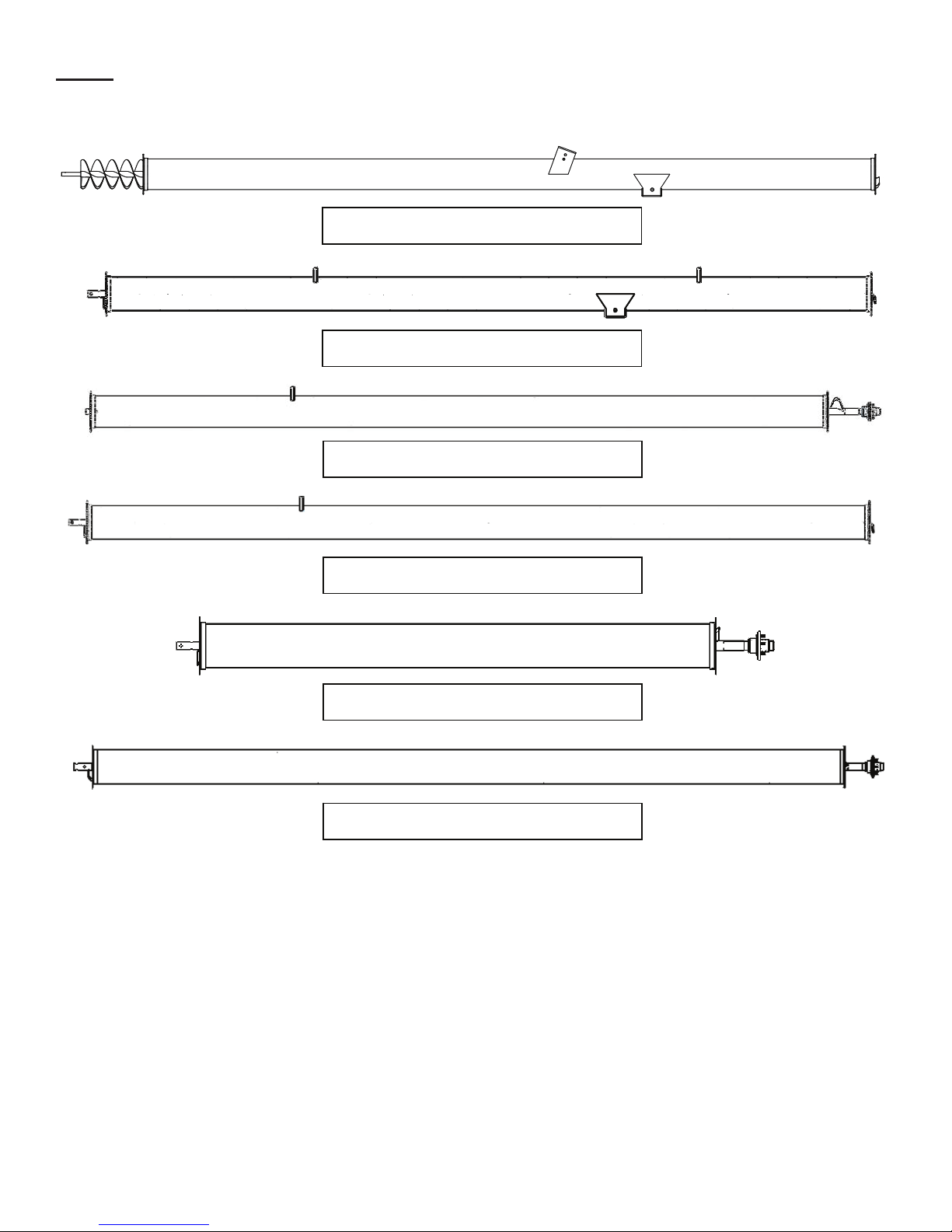
Step 1
Tube Identification
1st Tube H1062, H1072, & H1082
2nd Tube H1062, H1072, & H1082
3rd Tube, Discharge H1062
3rd Tube, H1072 & H1082
4th Tube, Discharge H1072
4th Tube, Discharge H1082

Page4of34
Harvestby MeridianH10XXAssemblyManual
Step 2(Tube & Flighting Assembly)
Place tubes on assembly stands as shown. Place stands 12” or less from the end of the tube. Placing stands
further than 12” from end of the tube may cause damage to the tubes.
Step 3
Slide the flighting together from the 1st & 2nd tube. Connect the flighting using (2) 1/2" x 2-1/2” hex bolts and
top lock nuts. Align flighting as shown to make contineous. After connecting the flighting, slide the 1st & 2nd
tube together putting in the top 2 & bottom (2) 1/2" x 1-1/2” flange bolts & nuts. If assembling an H1082, snug
up the top bolts as they will need to be removed in step 5. If assembling H1082, after completeing Step 3 please
skip to Step 5.
Step 4
Place the left (10192) & right (10193) bolt on cable truss mount brackets onto the tubes & using (4)
1/2" x 1-1/2” flange bolts & nuts. (Note: The left bracket will have a small notch cut into the top of it) Tighten
all 8 bolts around tube flange. Skip to Step 6.
Fig. 2.1
Fig. 3.1
Fig. 4.1
Page5of34
Harvestby MeridianH10XXAssemblyManual
Step 5 (H1082 Only)
Place the left (10192), right (10193) & two of the upper (10256) bolt on cable truss mount brackets onto the
tubes & using (4) 1/2" x 1-1/2” flange bolts & nuts. The top 2 bolts will need to be removed to attach the 2
upper truss mount brackets. (Note: The left bracket will have a small notch cut into the top of it) Tighten all 8
bolts around tube flange.
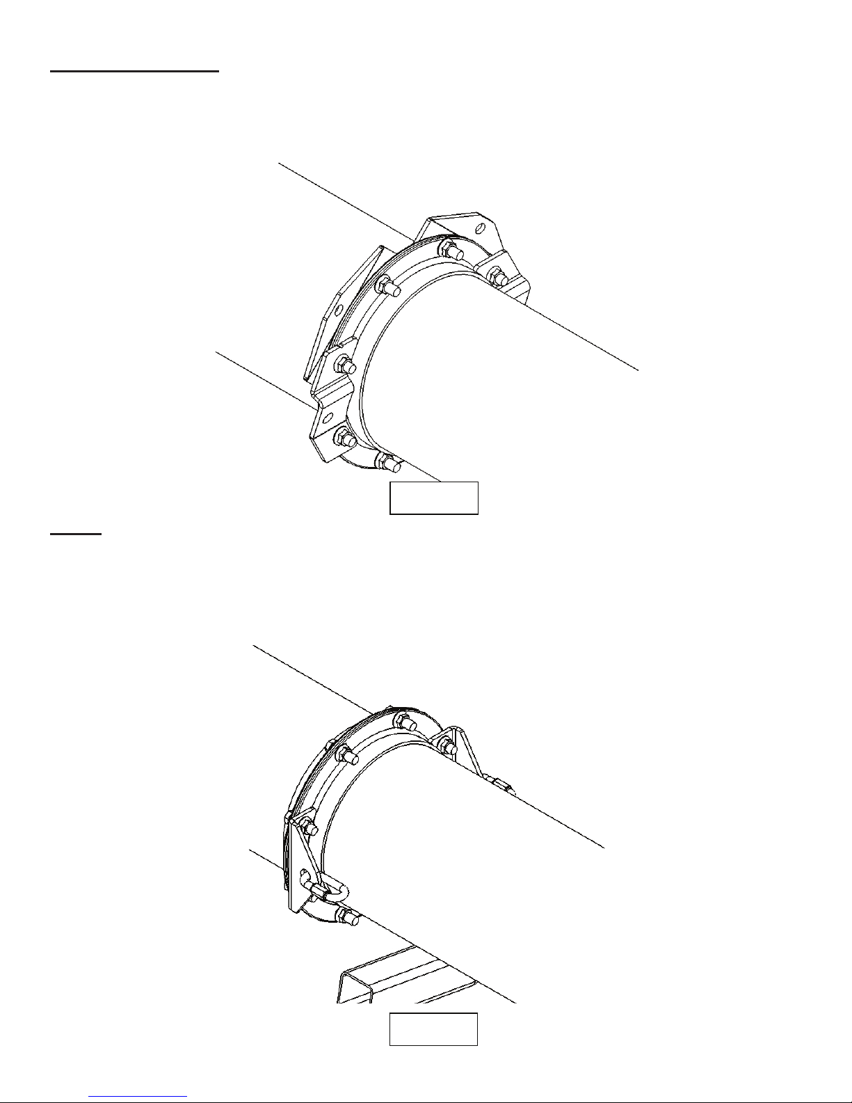
Step 6
Place the 3rd tube in front of the 2nd tube and connect the flighitng as shown in Step 3. After the flighting is
connected and secure, slide the 2nd & 3rd tube together as shown. Mount the cable attachment brackets (10171)
to the left and right side fo the flange on the 2nd tube. Tighten the tubes and brackets together using (8)
1/2" x 1-1/2” flange bolts & nuts. After the 8 bolts are tight, attached the 3/8” quicklink to each bracket as
shown. Tighten both quicklinks. If assembeling an H1062 please skip to Step 8.
Fig. 5.1
Fig. 6.1
Page6of34
Harvestby Meridian H10XXAssemblyManual
Step 7 (H1072 & H1082 Only)
Place the 4rd tube in front of the 3nd tube and connect the flighitng as shown in Step 3. After the flighting is
connected and secure, slide the 3rd & 4th tube together as shown. Mount the cable attachment brackets (10171)
to the left and right side fo the flange on the 3nd tube. Tighten the tubes and brackets together using (8)
1/2" x 1-1/2” flange bolts & nuts. After the 8 bolts are tight, attached the 3/8” quicklink to each bracket as
shown. Tighten both quicklinks.
Step 8 (Discharge Head Assembly)
All tubes & flighting should now be assembled together. Now the discharge head should be attached. First
align the 5 studs on the flighting with the 5 holes in the discharge head. Fasten the discharge head to the
flighting using (5) 1/2" lock washers & (5) 1/2" lug nuts. Thread lug nuts on flat side against the lock washers.
Tighten the 5 lug nuts. Next, fasten the discharge head to the tube using (2) 1/2" x 1-1/2” flange bolts & nuts &
(6) 1/2" x 1-1/2” hex bolts & flange nuts. The flange bolts are used on the top 2 holes of the discharge head as
shown. If assembling a H1072 or H1082 the cable attachment brackets (10171) & the 3/8” quick links will
need to be mounted on both the left and right side of the tube as shown in Step 6 & 7. Tighten all 8 bolts
mounting the discharge head to the tube. Tie red flag supplied in the kit to the discharge head.
Fig. 7.1
Fig. 8.1
Page7of34
Harvestby MeridianH10XXAssemblyManual
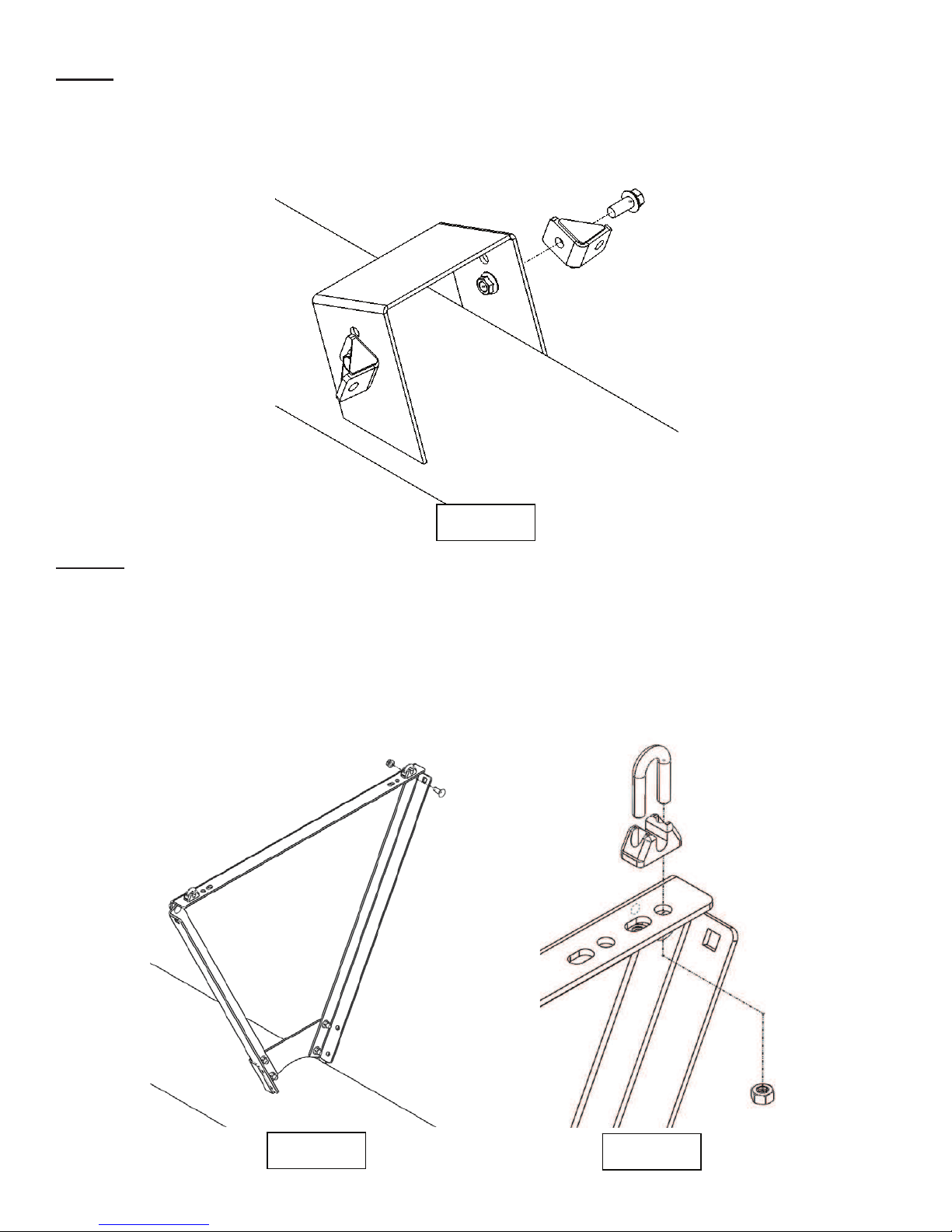
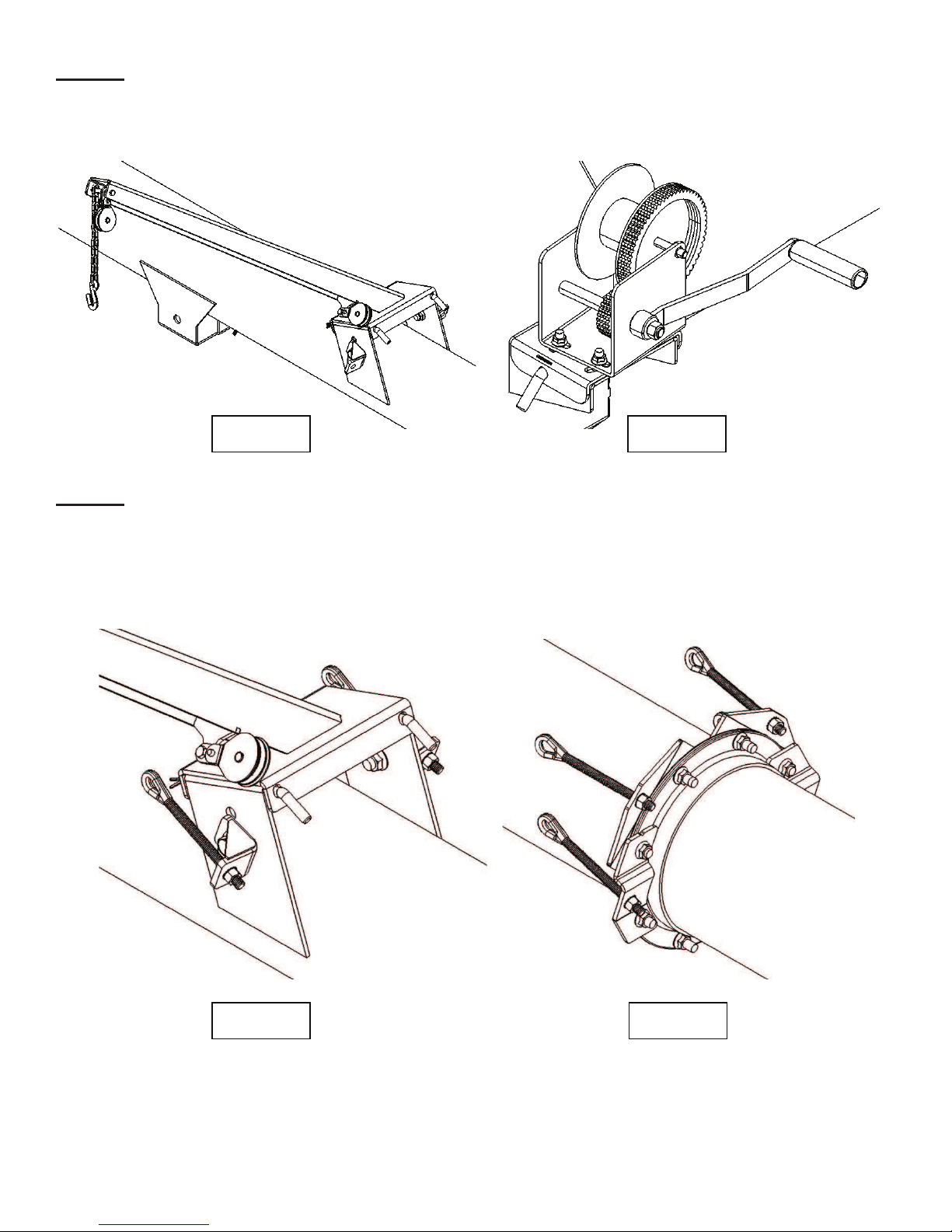
Step 9 (Cable Mount & Truss Assembly)
In Step 9 the lower cable mount brackets will be installed. On the 1st tube bolt cable mount brackets (30976) to
the left & right side of the hopper arm bracket as shown. These will be fastened using (2) 5/8” x 1-1/2” flange
bolts & nuts. Be sure to angle the cable mount bracket slightly upwards as shown in figure 9.1.
Step 10
Next the cable truss uprights and cross brackets will be assembled on the 2nd & 3rd tubes. Start by placing the 2
upright truss brackets (10163) on the tube and fastening with a total of (12) 3/8” x 1” carriage bolts & flange
nuts. Leave these a little loose for ease of assembling the cross member. Assemble the cross member (10174)
using a total of (6) 3/8” x 1” carriage bolts & flange nuts as shown. After all carriage bolts are tigtenen, place
the 3/8” cable clamps on the out side of the trusses as shown. Thread nuts on by hand but do not tighten. If
assembling an H1082 cable clamps will also have to be added on the inside holes on the upper and middle
trusses.
Fig. 9.1
Fig. 10.1 Fig. 10.2

Page8of34
HarvestIby Meridian H10XXAssemblyManual
Step 11 (Infeed Housing Assembly)
Loosen bolts and remove both access panels. Using a lifting strap, lift and slide the infeed housing over the
bottom flighting on the 1st tube. Secure the infeed housing to the first tube using (6) 1/2" x 1-1/2” flange bolts
and nuts & (2) 1/2" x 1/1-2” hex bolts & flange nuts. The (2) 1/2" x 1-1/2” hex bolts shoule be used on the
bottom holes and orientated as shown in fig. 11.4.
Fig. 11.1 Fig. 11.2
Fig. 11.3 Fig. 11.4

Page9of34
Harvestby Meridian H10XXAssemblyManual
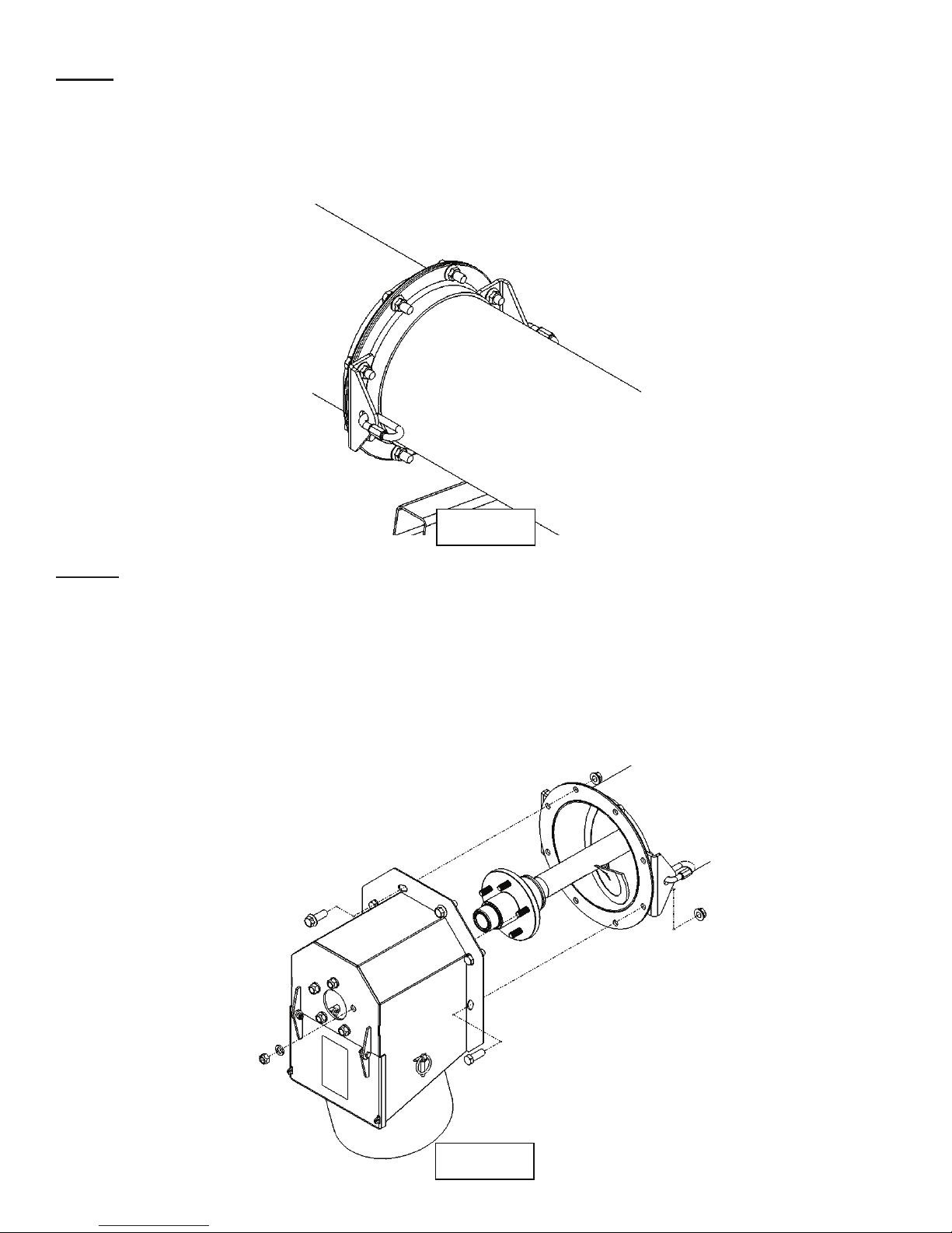
Step 12
Next, locate the gearbox mounted inside of the infeed housing. Remove the 2 top plugs in the gearbox &
replace the top one with the grease zerk & the bottom one with the breather provided.
Step 13
Next, slide the 4 botl 1-1/4” cast flange bearing over the shaft making sure the grease zerk is located on the
same side as the idler sprocket. (If the shaft has surface rust, clean first with an emry cloth) Secure the 4 bolt
bearing to the infeed housing using (4) 1/2" x 1-1/2” carriage bolts & flange nuts as shown. When completed
use a punch to rotate the shaft so the keyway is in an easy to access position.
Fig. 12.1
Fig. 13.1
Page10of34
Harvestby MeridianH10XXAssemblyManual
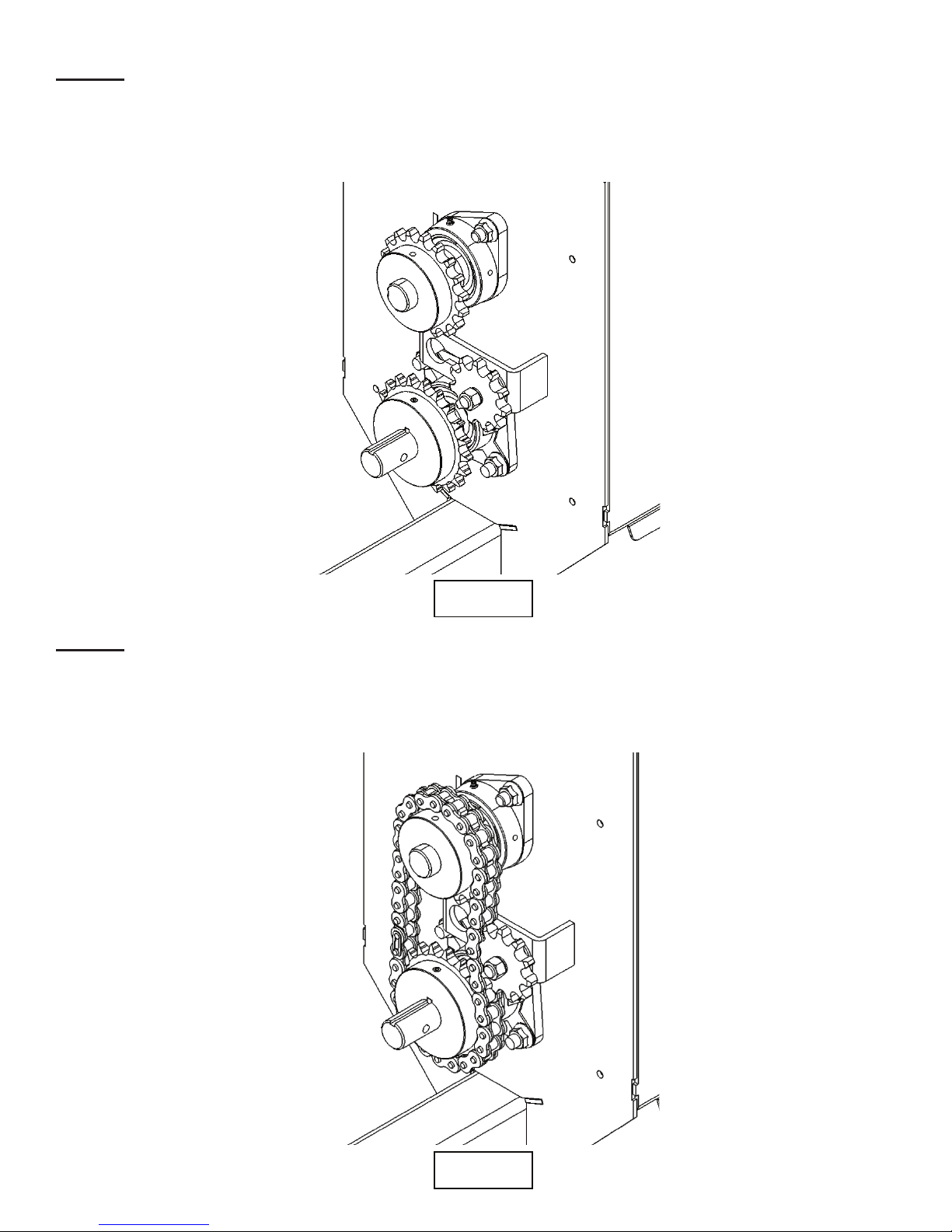
Step 14
Next, insert (2) 1/4" x 1” square keys into the top & bottom shaft. Slide the 18 tooth sprocket onto the top shaft
& the 20 tooth sprocket onto the bottom shaft as shown in fig. 14.1. Use a measuring tape & measure the
distance from the center of each sprocket to the infeed housing. Once sprockets are aligned, apply lock-tite to
set screws & tighten.
Step 15
Locate the #60 chain, #60 half link, & #60 connector link. Attach the half link to the chain on one end & place
the chain around the sprockets as shown in fig. 15.1. Secure chain with connector link. When connector link is
installed & the loop has been completed, push the idler sprocket in the chain to achieve good tension. When
proper tension is achieved tighten the idler sprocket. Now grease top & bottom bearings with multi-lith grease.
Fig. 14.1
Fig. 15.1

Page11of34
Harvestby Meridian H10XXAssemblyManual
Step 16 (PTO Shaft Assembly)
Next, insert a 1/4" x 1” square key into the bottom shaft. Slide PTO shaft onto lower drive shaft. Align holes in
PTO shaft with hole in drive shaft. Using a punch will help in this application. Secure using a 5/16” x 3” hex
bolt & top lock nut. Tighten set screw on PTO shaft.
Step 17
Next slide the chain guard over the PTO shaft and secure to the infeed housing (4) 3/8” x 3/4" flange bolts.
Then place lower “U” shaped guard place onto guard and secure with (4) 3/8” x 3/4" flange bolts.
Fig. 16.1 Fig. 16.2
Fig. 17.1
Page12of34
Harvestby Meridian H10XXAssemblyManual
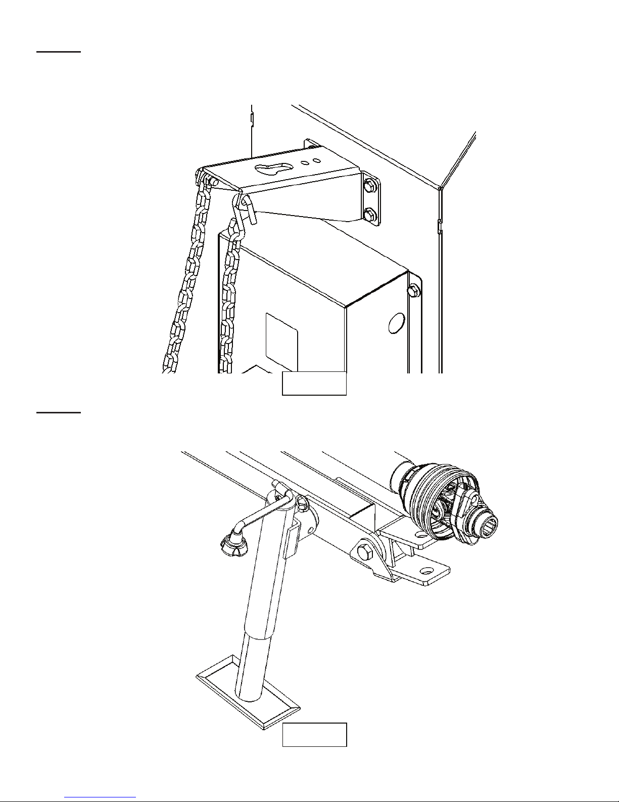
Step 18
Locate the PTO support bracket & mount it to the infeed housing as shown in fig. 18.1 using (4) 3/8” x 3/4"
flange bolts & flange nuts. Attach the PTO support chain to the bracket as shown using a 3/8” x 1” flange bolt
& flange nut.
Step 19
Locate the jack and slide it onto the jack mount tube located on the side of the tongue. Secure jack with pin.
Fig. 18.1
Fig. 19.1
Page13of34
HarvestIby Meridian H10XXAssemblyManual
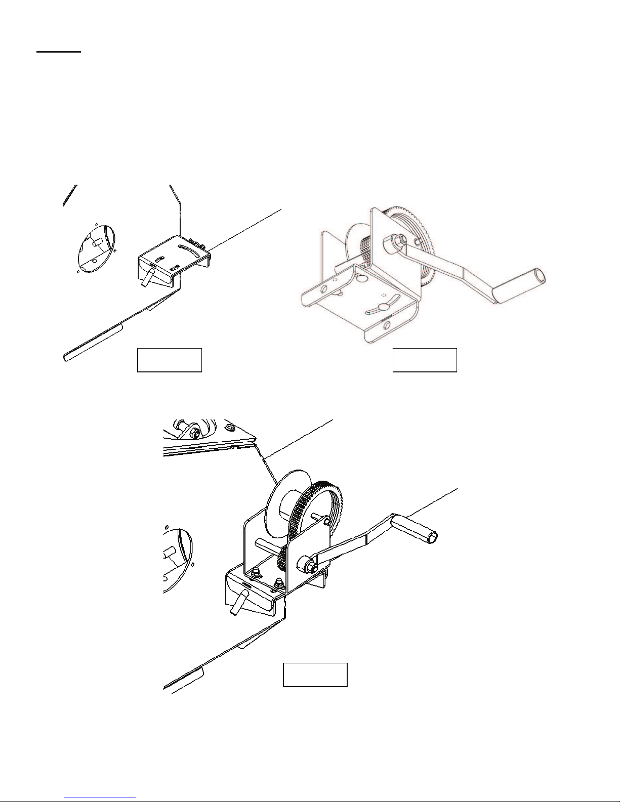
Step 20
Next the hopper winch will be mounted. On the right side of the infeed housing there is a bracket with a pin
through it. (Fig. 20.1) Remove pine & set aside. Remove bracket & attach to winch using (3) 3/8” x 1”
carriage bolts & flange nuts as shown in fig. 20.2. Tighten bolts by hand only for now. Slide the winch handle
onto winch with spring & nut. Tighten nut to secure handle. Place winch on top of bracket welded to the infeed
housing and secure with the pin. Angle the winch so it is centered with the top bracket (hopper arm bracket) on
the 1st tube as shown in figure 20.3. Tighten the (3) 3/8” x 1” carriage bolts.
Fig. 20.1 Fig. 20.2
Fig. 20.3
Page14of34
Harvestby Meridian H10XXAssemblyManual
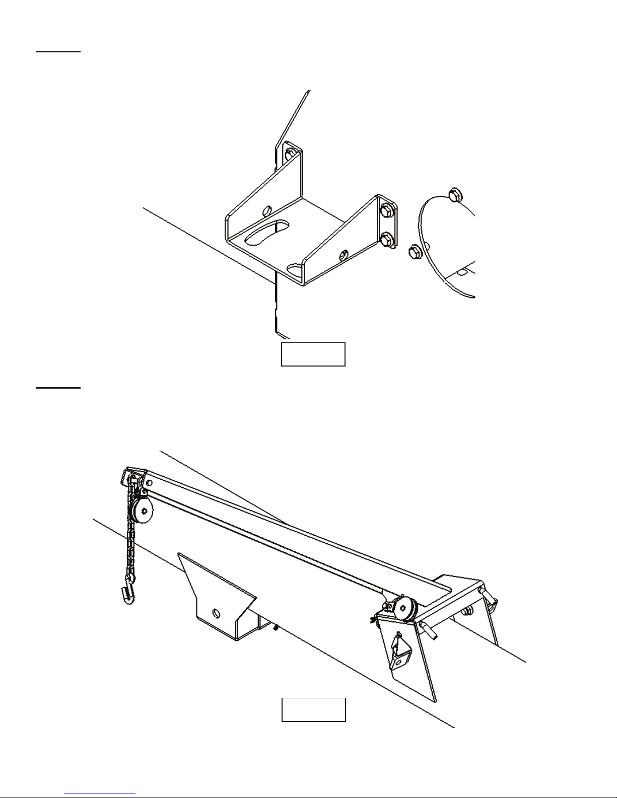
Step 21
Next mount the left hand winch bracket (10131B) to the left side of the infeed housing. Attatch the bracket
using (4) 3/8” x 1” flange bolts & flange nuts.
Step 22
After the left hand side winch mount bracket is secured assemble the hopper transport arm to the 1st tube. This
will be done using (2) 1/2" x 7” bent pins as shown in figure 22.1.
Fig. 21.1
Fig. 22.1
Page15of34
Harvestby Meridian H10XXAssemblyManual
Step 23
Next the hopper lift cable will be assembled. Insert cable through the upper then the lower pulley on the hopper
transport arm. Pull cable back to the winch. Insert cable through hole on the side of the winch drum. Fasten to
winch using the winch cable clamp & nut profided with winch.
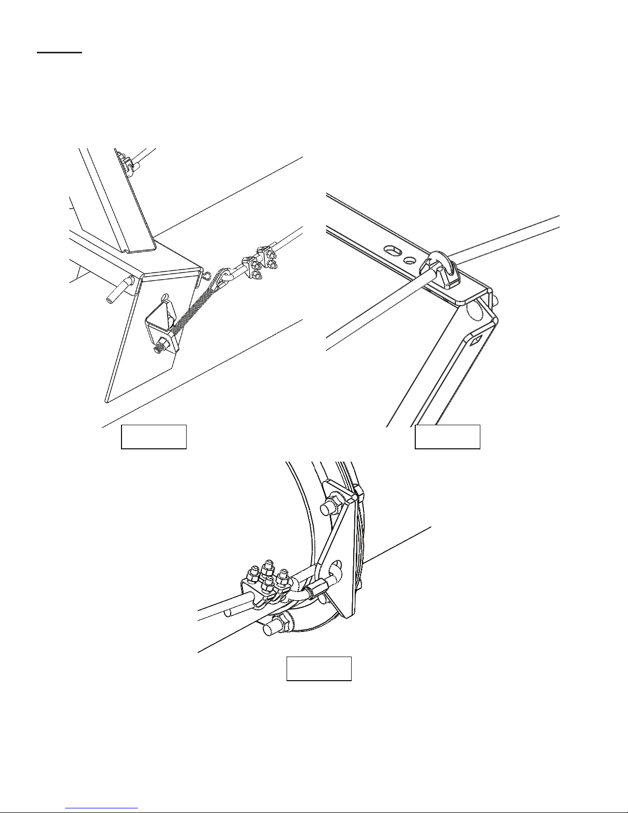
Step 24 (Truss Cable Assembly)
First assemble all the eyebolts to the lower cable mount brackets. Assemble the eyebolts to the transport arm
bracket & the connecting flanges of the 1st & 2nd tube. Attaching the eyebolts will include (4) 1/2" eyebolts,
1/2" external tooth lock washers & 1/2" hex nuts. Thread nut onto eyebolt so 1/2" is sticking out past the nut.
If assembling an H1082 there will be 6 of each fastener used.
Fig. 23.1 Fig. 23.1
Fig. 24.1 Fig. 24.2
Page16of34
Harvestby Meridian H10XXAssemblyManual
Step 25
Take 1 short 29 foot cable & attach it to the eyebolt located in the middle of the first tube. Secure using (2) 3/8”
cable clamps as shown if fig. 25.1. Pull cable to first truss and through the cable clamp located on the truss.
When the cable is through the cable clamp, continue pulling the cable to the quicklink located on the joint
between the 2nd & 3rd tube. Secure using (2) 3/8” cable clamps as shown if figure 25.2. Repeat on opposite side
of the auger. Always have saddles of the cable clamps on the “live” end of the cable. If assembling an H1082
skip Step 26 and go to Step 27.
Fig. 25.1 Fig. 25.2
Fig. 25.3
Page17of34
Harvestby Meridian H10XXAssemblyManual
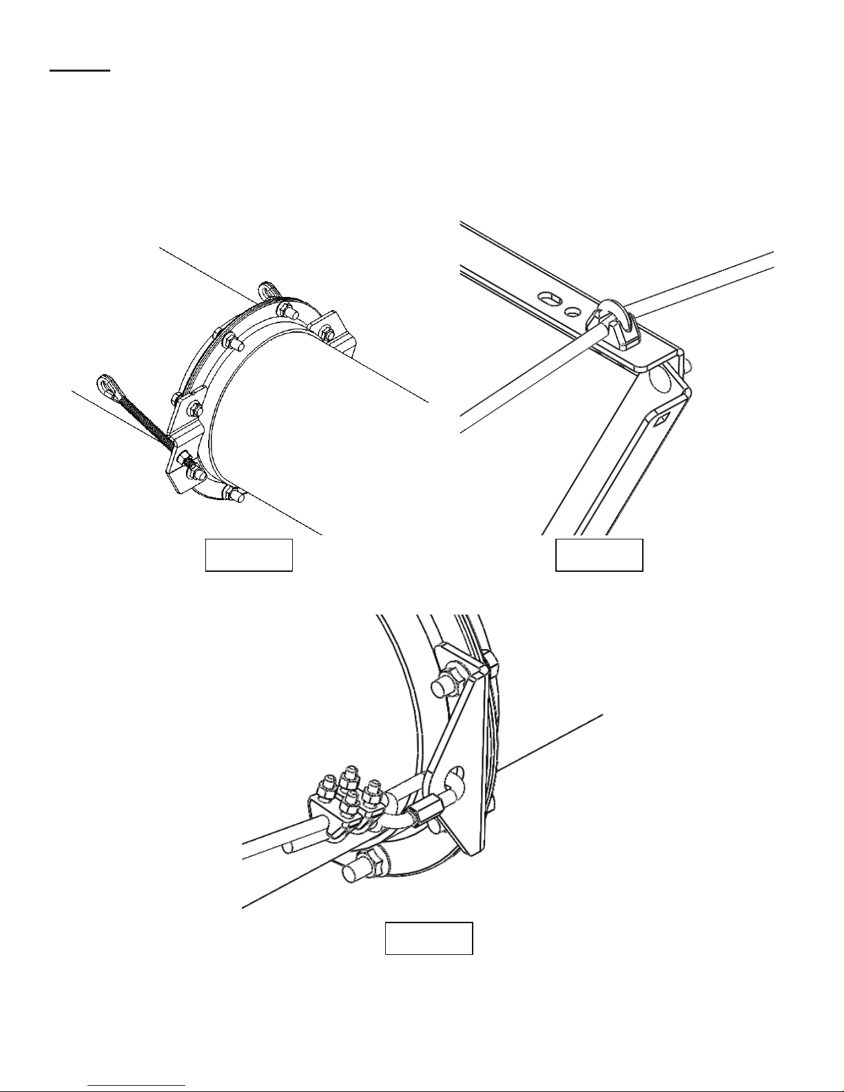
Step 26
Locate the 41 foot cables. Attach cable to eyebolts on the left & right side cable truss mount brackets. Attach
using the same process specified in step 25. Pull cable past the first truss keeping the cable on the outside of
the truss. Put the cable through the outer cable clamps located on the 2nd & 3rd truss. When the cable is through
both cable clamps, continue pulling the cable to the quicklink located on the joint on the end of the 3rd tube.
Secure using (2) 3/8” cable clamps as shown if fig. 26.3. Repeat on opposite side of the auger. On an H1062
this will be the discharge head joint. If assembling an H1062 & H1072 skip Step 27 and Step 28. Go to Step
29.
Fig. 26.1 Fig. 26.2
Fig. 26.3
Page18of34
Harvestby MeridianH10XXAssemblyManual
Step 27 (H1082 Only)
Locate the 41 foot cables. Attach cable to eyebolts on the top cable truss mount brackets. Attach using the
same process specified in step 25. Pull cable past the first truss running them on the inside of the truss. Put the
cable through the inner cable clamps located on the 2nd & 3rd truss. When the cable is through both cable
clamps, continue pulling the cable to the quicklink located on the joint on the end of the 3rd tube. Secure using
(2) 3/8” cable clamps as shown if fig. 26.3. Repeat on opposite side of the auger.
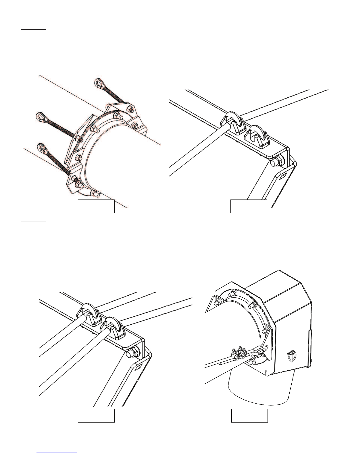
Step 28 (H1082 Only)
Locate the 61 foot cables. Attach cable to eyebolts on the left & right side cable truss mount brackets (Fig.
27.1). Attach using the same process specified in step 25. Pull cable past the first truss keeping the cable on
the outside of the truss. Put the cable through the outer cable clamps located on the 2nd & 3rd truss. When the
cable is through both cable clamps, continue pulling the cable to the quicklink located on the joint on the end of
the 4rd tube. Secure using (2) 3/8” cable clamps as shown if fig. 28.2. Repeat on opposite side of the auger.
Fig. 27.1 Fig. 27.2
Fig. 28.1 Fig. 28.2

Page19of34
Harvestby Meridian H10XXAssemblyManual
Step 29
To tighten the cables, lifting the discharge end of the tubes is required. Place a lifting strap 2 feet from the end
of the auger and lift the tubes approximently 3 feet. This will cause the tubes to curve upwards. Place a punch
or pry bar into the eye of the eyebolt to hold it straight. Tighten the nut on the eyebolt about 3” or until the
cable feels stiff. Do this for all the cables. (4 cables on an H1062 & H1072; 6 cables on an H1082)
Step 30
When all the eyebolts are tightened it is now time to tighten the truss cable clamps. Tighten each cable clamp
that is mounted to each truss evenly. (6 cable clamps on an H1062 & H1072; 10 cable clamps on an H1082)
After the clamps are tightened, stabilize the auger and lower the discharge end of the auger. Once lowered, the
auger shoud have a bow of 3” to 4” off of the assembly stand.
Fig. 29.1 Fig. 29.2
Fig. 30.1 Fig. 30.2
Page20of34
Harvestby Meridian H10XXAssemblyManual
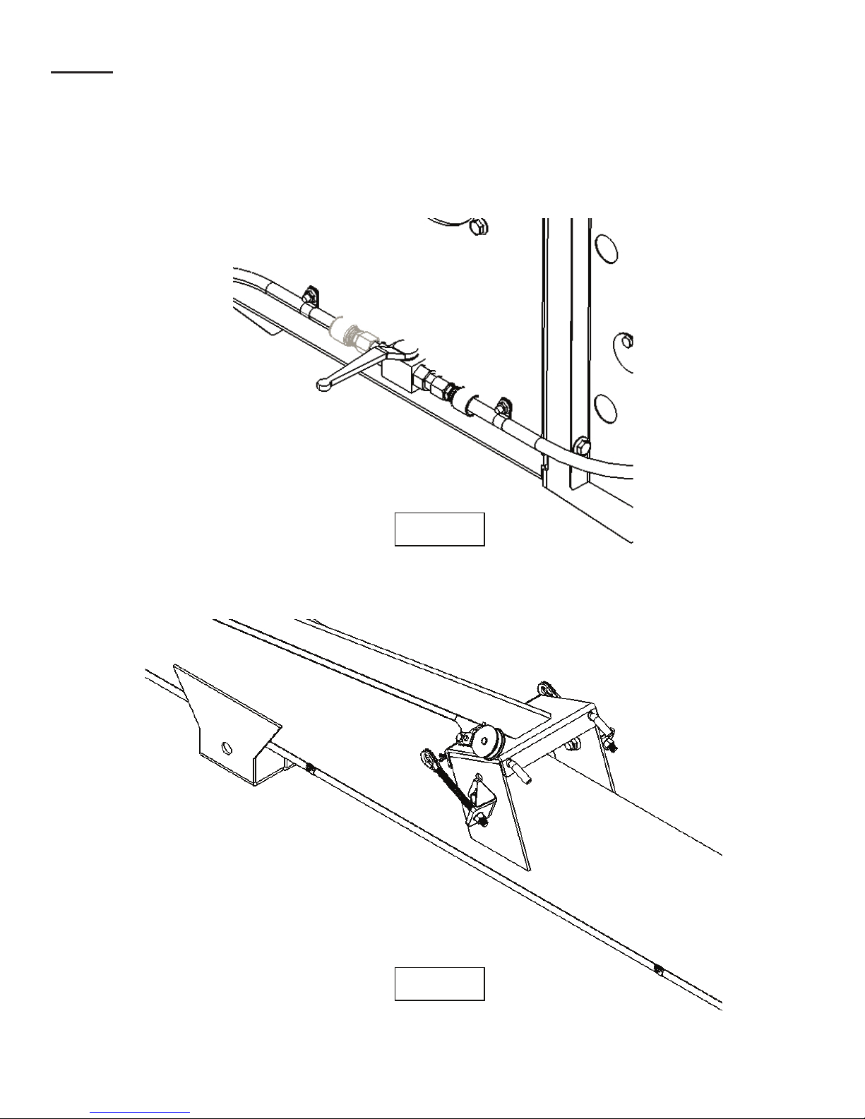
Step 31 (Hydraulic Hose Assembly)
Locate the hydaulic kit and the quarter turn shut off valve. Attach the hoses and shut off valve to the left side of
the infeed housing using (2) 1/2" hose “P” clamps & (2) 1/4" x 3/4" flange bolts & nuts as shown in figure 31.1.
Run hose up left hand side auger tube attaching it the weld on studs using 1/2" hose “P” clamps & 1/4" flange
nuts. Leave a little slack between each stud. Run the house on the inside of the carriage mount bracket as
shown in figure 31.2.
Fig. 31.1
Fig. 31.2
This manual suits for next models
2
Table of contents
Other HARVEST Tools manuals


