ujk technology 719241 User manual

Compact Router Table
Kit Code 717126
Kit Code 719241
AT&M: 23/05/2019
BOOK REF: 104389
Hole assembly instructions including the UJK table
tops, fence assembly, table inserts and other accessories
Original Instructions

Index of Contents
2
• Introduction 03
• What’s Included 04-05-06-07
• Optional Accessories 08-09-10-11
• Kit Specification 12
• General Instructions for 230V Machines 12
• General Safety Instructions 13
• Assembly 14-15-16-17-18-19-20-21
• Illustration & Parts Description 22-23
• Mounting the Router to the Universal Base Plate 24-25
• Mounting the Router to the 10mm Table Inserts 26-27-28
• Operating Instructions 28
• General Guide to Router Cutters 29-30
• Exploded Diagram/Parts LIst 31-32-33-34-35
Fully read manual
and safety instructions
before use
Eye protection
should be worn
Ear protection
should be worn
Dust mask
should be worn
The symbols below advise the correct safety procedures when using this machine.

Introduction
3
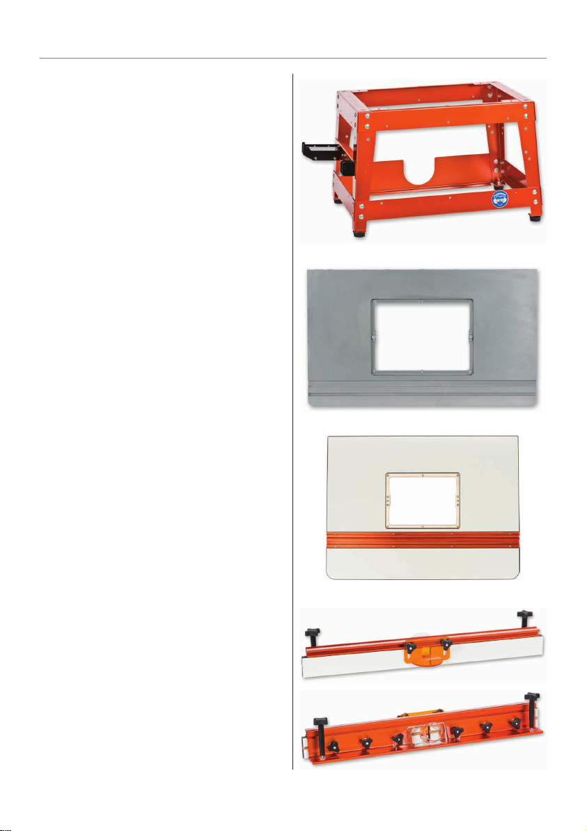
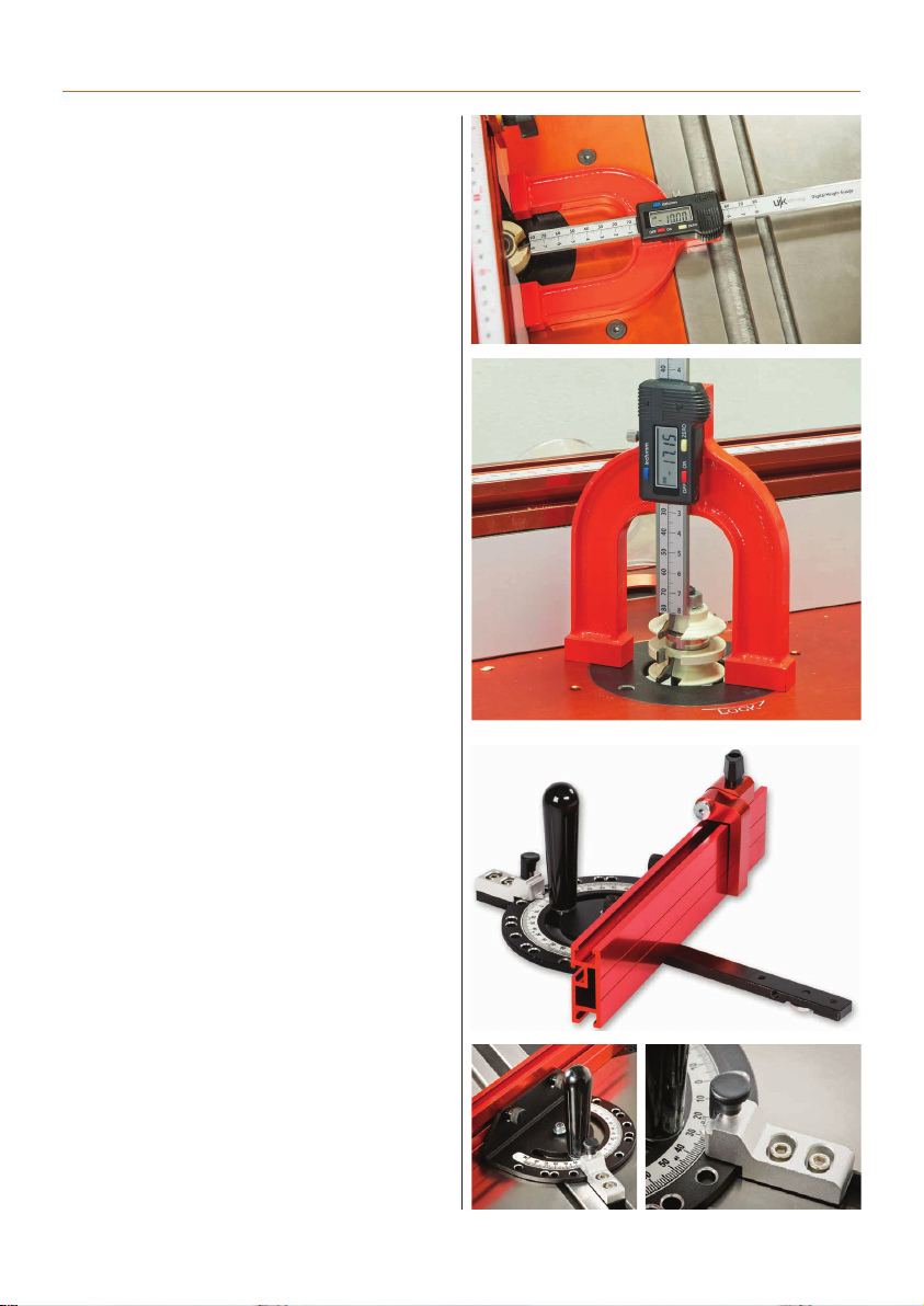
The UJK Technology Compact Leg Stand with splayed legs
is of sturdy construction, very stable and of a size that offers
portability around the workshop or on site. Provision is made
for storage of the supplied mitre fence assembly.Measuring
370mm high, with a footprint of 580 x 390mm, this leg stand is
such a useful size and could also be used for mounting many
other small machines.
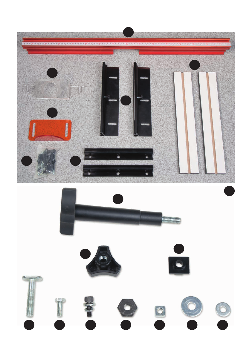
The UJK Technology Compact Router Table Fence is a
beautifully made, single piece aluminium section supplied
with a transparent 63mm dust port for efficient extraction from
above the table.Provision is made for the fitting of guards and
accessories with a T-slot at both the top and front of the fence.
An adjustable transparent guard is included for your safety.
Adjustable scales are provided for attachment at either side of
the table and the fence is attached to these locking into place
in the required position. A scale is also provided along the top
of the fence with the zero position at the centre.Adjustable
infeed and outfeed fences attach to either side of the
aluminium section and the central aperture can be opened
and closed according to the diameter of the cutter in use.
Fence measures 789 x 90mm.
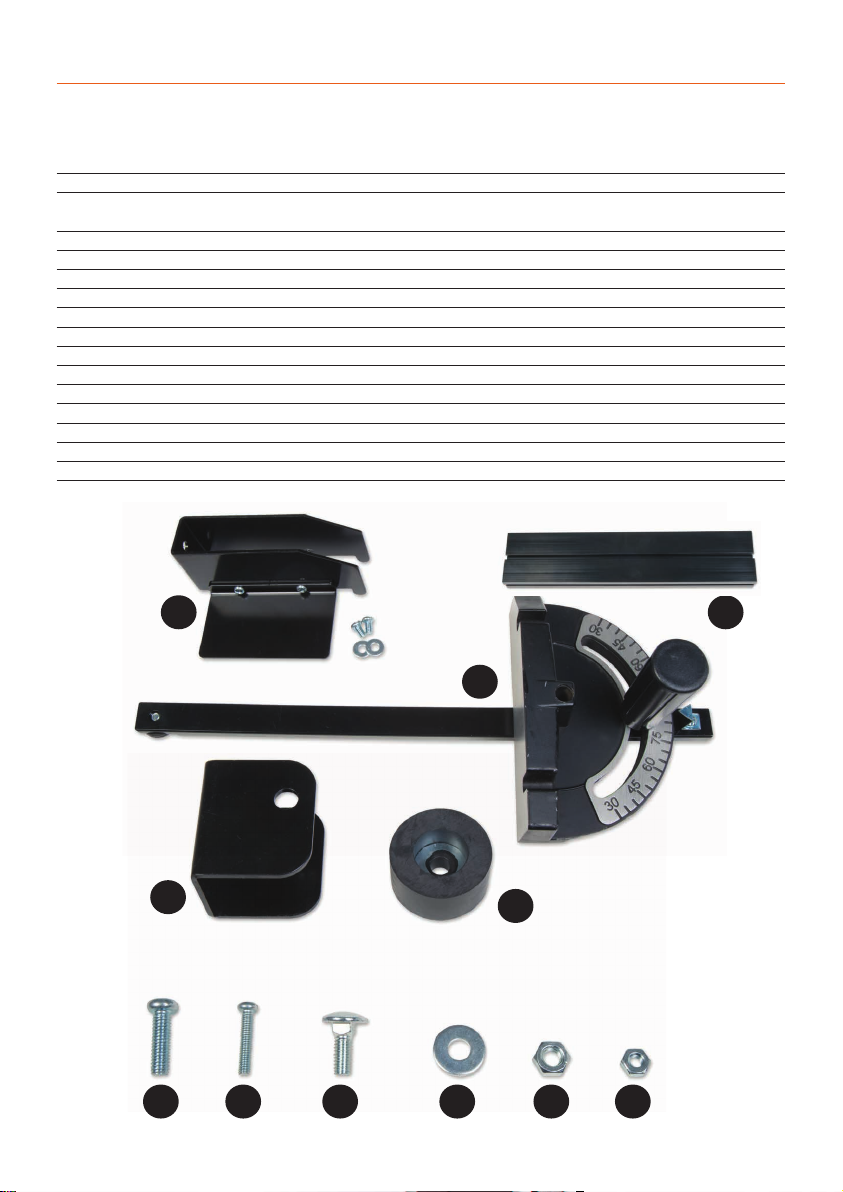
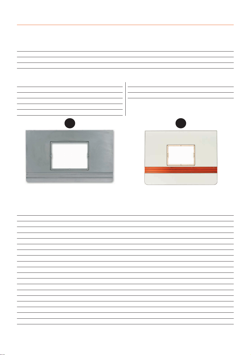
The UJK Technology Compact Cast Iron Router Table Top
is one of a range of options that you can choose from when
making up your UJK router table. Simply add the leg stand,
fence and required insert and you will have a very sturdy
versatile unit capable of many routing operations.The benefits
of using cast iron for the manufacture of machine tables are
well known especially where vibration damping and stability
are paramount.The quality of the surface grinding on this
686 x 406 x 40mm top is superb, offering little resistance when
passing stock across the table during use. A standard 19mm
wide slot is incorporated for the use of a mitre fence
attachment and a T-slot is also present for jigs and accessories.
The top is threaded to accept the UJK compact leg stand, fence
assembly and optional dust collection box.The 230 x 306mm
central aperture will accept the router elevator and other
available UJK insert options.
The UJK Technology Compact Laminated Router Table
Top is high grade birch ply with a hard wearing, low friction,
phenolic laminated surface.The ply core ensures the top will
remain flat throughout its working life, while the laminated top
ensures workpieces glide smoothly. An extruded aluminium
track inset into the tabletop includes a standard 19mm track
for the use of a mitre fence and a T-track slot for other jigs and
accessories.The 230 x 306mm central aperture will accept any
of the UJK Technology router table inserts as well as the UJK
router elevator.The top measures 600 x 400 and is pre-drilled
to fit the UJK Compact router table leg stand, fence assembly
or optional dust collection box.

What’s Included
4
Quantity Item Part Code
502533
Bag 1 Containing:
1 No Mitre Fence Bracket Holder with two Phillips
screws and washers 1
Bag 2 Containing:
1 No Tool Bracket (with two pre-drilled holes) 2
4 No Rubber Feet 3
4 No Phillips Screws (M6x20mm) 4
2 No Phillips Screws (M4x20mm) 5
34 No Coach Bolts (M6x12mm) 6
38 No Flat Washers (M6) 7
38 No Nuts (M6) 8
2 No Nuts (M4) 9
1 No Mitre Fence 10
1 No Mitre Fence Extension
(with two Butterfly nuts and washers) 11
UJK Router Table Stand
1
10
11
23
4 5 6 7 8 9

What’s Included
5
Quantity Item Part Code
502533
4 No Leg Supports Brackets A
2 No Front and Back Upper Panels B
1 No Front Lower Panel C
2 No Side Lower Panels D
2 No Side Upper Panels E
1 No Side Centre Panel F
1 No Rear Extractor Panels G
UJK Router Table Stand
A
B
G
D E F
C
Continues Over...

What’s Included
6
Bag Containing Code 502532
10 No Countersink Phillips Screws (M6x20mm)
10 No M6 Nuts
10 No Hex Bolts (M6x12mm)
10 No M6 Washers
10 No Spring Washers
Bag Containing Code 102544
10 No Countersink Phillips Wood Screws
6 No Phillips Head Wood Screws
UJK Router Table Tops
Quantity Item Part Code
1 No UJK Compact Cast Iron router table top A502532
1 No UJK Compact Laminated router table top B102544
A
UJK Pro Cast Iron Table Top
B
UJK Laminated Table Top
Quantity Item Part Code
508272
1 No Fence H
1 No Extraction Moulding I
1 No Dust Shield J
2 No Fence Fixing Brackets with Scale K
2 No Fence Fixing Brackets L
2 No Adjustable Wood Faces M
1 No Bag Containing N
2 No Locking Handle Knob (5/16”) a
8 No M8 Locking Knobs b
2 No Fence Spacers c
8 No ‘T’ Bolts (M8x43mm) d
6 No Hex Screws (M6x12mm) e
6 No Hex Bolts (1/4”) (with flat & spring washers) f
2 No Lock Hex Nuts (5/16”) g
6 No Square Nuts (1/4”) h
10 No M8 Flat Washers i
6 No M6 Flat Washers j
UJK Fence Assembly

What’s Included
7
a
bc
defgh i j
N
H
I
J
K
M
LN

Optional Accessories
8
1) UJK Technology QuickStop
(Code 502569)
•A hinged stop to fit the UJK
Technology router tables.
•An excellent device for stopped
chamfers or rebates.
•Attaches to the top of the router
table fence.
•Simply flips up out of the way when not required.
2) UJK 10mm Aluminium Router
Table Insert c/w Universal Base
(Code 502748)
UJK 10mm Aluminium Table Insert
(Code 105932)
• Threaded lead-in pin.
• To fit 230 x 306mm aperture.
• Twist lock insert ring supplied with wrench.
3) Router Table Inserts
• A range of central inserts for the
• Axminster or UJK router elevator
• Also suitable for UJK Technology aluminium and phenolic
router table insert plates.
• Sizes include 12.6mm, 38mm, 63.4mm plus a guide bush
adaptor.
• Blank insert available for making your own hole size.
• Available as a set of four or individually.
(Code 502565) 12.6mm
(Code 502566) 38mm
(Code 502567) 63.4mm
(Code 951187) Blank Insert
(Code 502525) Guide Bush Adaptor
4) Vertical Feather Boards
(Code 502751)
• Gives downward pressure against workpiece.
• Excellent for safer routing.
5) Horizontal Feather Boards
(Code 502750)
• Holds workpiece against fence.
• Excellent for safer routing.
• Use as singles or stacked for more support.
502566
502567
502565
105932
502748
502525
951187
502751
502750

Optional Accessories
9
6) UJK Technology Router Elevator
(Code 502701)
The UJK Technology router elevator is a logical solution for
fast, accurate production on many router table installations.
This compact design was developed by us to fit straight
into our own router tables and most table set-ups can
accommodate this size of insert (305 x 229 x 6mm).The unit
can be made to fit flush into the tabletop by the provision
of levelling screws at each corner of the table insert. Height
adjustment is carried out by inserting a handle through a
measurement dial set into the machine table. Each rotation
of the handle raises or lowers the cutter by exactly 2mm
and the integral scale is graduated into increments ena-
bling very accurate adjustments to be carried out.
7) UJK Technology Dust
Extraction Box
(Code 502538)
• Dust collection device.
• Efficient extraction from above and below the table.
•Access door with magnetic catch.
•63mm extraction hose included.
•100mm outlet.
Dust extraction from a router table can be difficult and for it to
work effectively it needs to extract from both above and below
the table. Designed to fit the UJK Technology Pro and Compact
router tables this device fits below the table top enclosing the
router. It could also be fitted to other custom made tables of
your own design.The 100mm diameter outlet on the back also
incorporates a 62mm inlet and hose which enables extraction
from both above and below the table simultaneously. An
access door is provided on the front with a magnetic closure
enabling access to your router for adjustments if required.
Measures 330 x 260 x 350mm high with an access aperture of
225 x 170mm.
8) UJK Technology Off Set Bars for Router Tables
(Code 103561)
A pair, these H-section extrusions fit behind the outfeed
fence of the UJK router table fence. Once in position they
give you an exact 1mm offset between the infeed and
outfeed fences. Their clever design means you can rotate
each extrusion by 180° and reinsert them in position to
achieve an exact 2mm offset.
Continues Over...

Optional Accessories
10
9) UJK Technology Digital Height Gauge
(Code 103655)
The UJK Technology Digital Height Gauge is an
indispensable measuring tool for the accurate setting of
cutting depths, in particular router cutters and saw blades.
The body is cast iron, with machined feet that form a
reference surface. It is stable and can stand upright without
additional support. It is equally accurate both vertically and
horizontally.The horseshoe shaped body measures 54mm
between the legs with an internal height of 80mm.The
main feature is its highly accurate digital scale unit, with an
LCD screen offering a read-out in either metric or imperial.
The display has a resolution of 0.01mm or 0.001 inches.
The digital read-out tells you precisely how deep your saw
blade or router cutter is going to cut.With a measuring
speed of 1.5 milliseconds, it is somewhat faster than
making a guess with a ruler. You can zero the digital
read-out at any point, allowing relative adjustment.It is
particularly handy to hold the bar in contact with the blade
or cutter and gradually increase the cutter height until the
display reaches the desired depth.Used horizontally, you
can measure or adjust a router table fence relative to the
cutter.The UJK Technology Digital Height Gauge will also
measure a mortice to a depth of 99mm.
10) UJK Technology Compact Mitre Gauge & Fence
(Code 101585)
Our fence improves safety and accuracy when cutting or
sanding and makes it easy to cut perfect mitres quickly.
The protractor head features positive stops at 0°, 22.5°, 30°,
45°, 60°, 67.5° and 90°, both left and right.This gives you
13 pre-set common angles in total.The clear easily read
scale allows you to set the head to any intermediate angle.
To select an angle you simply loosen the clamp handle
and lift the indent plunger. Move the fence along until the
plunger seats itself in the indent corresponding to the
angle required. Re-tighten the angle clamp knob and carry
on with the job.
The bar is 320mm long with a removable locking washer
making it usable with any standard 19 x 9.5mm (3/4”x
3/8”) track or similar sized T-slot. Three sprung loaded ball
bearings keep the bar snug in the track; the fence runs true
without side-play.
The rugged 300mm long, 60mm high aluminium fence
comes complete with flip-up length stop.

Optional Accessories
11
11) UJK Technology Professional Coping Sled
(Code 102946)
When profiling the end grain of a narrow workpiece on
the router table,you need a way of holding the workpiece.
This is particularly relevant if your workpiece is narrower
than the gap in your router fence.The UJK Technology
Coping Sled holds the key to working safely, securely and
achieving accurate results.
Developed and extensively tested by UJK Technology, this
Coping Sled will transform the way you make end grain
cuts for rail and stile doors, tenons and many other joints.
If you are intending to make cabinet doors on your router
table, the Coping Sled is invaluable. It is by far the best wa
to secure your workpiece, offering perfect results with a
high degree of safety.The Coping Sled takes the stress out
of the process. It ensures your workpiece is square to the
table’s mitre slot and that it guides smoothly across the
router bit.
The Coping Sled secures your workpiece both horizontally
and vertically. A slotted top plate holds the work firmly
against the sled’s rear fence. This plate prevents kickback
and easily adjusts for material up to 135mm wide. Two
vertical clamps prevent the workpiece lifting during the
cut.The position of the foremost clamp, close to the point
of cut, significantly reduces vibration.The maximum
workpiece thickness is 40mm.
To prevent tear-out at the end of the cut, the Coping
Sled has a 45mm wide x 22mm deep nylon fence. Unlike
aluminium, nylon will not damage your router cutter.You
can use the fence as a spelcher if you wish or use an off-cut
to prevent tear-out. The fence includes a sliding flip-stop for
repeat cuts. A T-slot cutter is available should you wish to
make a replacement or custom wooden fence.
On the underside of the 10mm thick, low-friction base-
board is a 19 x 9.5mm (3/4”x 3/8”) mitre slot bar. It will fit
both plain and T-slot mitre slots.Two grub screws, 150mm
apart, allow adjustment for zero play in the slot.The bar has
a choice of five positions to accommodate a wide variety of
router tables.
Two large rubberised handles provide a firm safe grip for
complete control.The design allows you to position the
handles directly over the work.The sled’s handles make
sure both your hands remain a safe distance from the
router bit. A clear, full width Plexiglas shield acts as a chip
deflector.

Kit Specification
12
Code 717126
Rating Trade
Table Size 686 x 406 x 40mm
Fence Size 789 x 90mm
Dust Extraction Outlet 62mm
UJK Technology Compact Router Table with Cast Iron Table Top
Code 719241
Rating Trade
Table Size 600 x 400 x 22mm
Fence Size 789 x 90mm
Dust Extraction Outlet 62mm
UJK Technology Compact Router Table with Laminated Table Top
General Instructions for 230V Machines
Good Working Practices/Safety
General Advice
Mains Powered Tools/ Primary Precautions
The following suggestions will enable you to observe good
working practices, keep yourself and fellow workers safe
and maintain your tools and equipment in good working
order.
WARNING! KEEP TOOLS AND
EQUIPMENT OUT OF THE REACH
OF YOUNG CHILDREN
If you are totally unfamiliar with the use of a power
router, please seek some basic tuition and advice from an
informed, qualified source. An amateur woodworker or
hobbyist just starting out is advised to undertake a short
course on the use of woodworking machines run by a
professional woodworker.These are often offered by your
local authority as evening classes.
These tools are supplied with a moulded 13 Amp. plug and
3 core power cable. Before using the tool inspect the cable
and the plug to make sure that neither are damaged. If
any damage is visible have the tool inspected/repaired by
a suitably qualified person. If it is necessary to replace the
plug, it is preferable to use an ‘unbreakable’type that will
resist damage on site.Only use a 13 Amp plug, make sure
the cable clamp is tightened securely and check that a 13
Amp fuse is fitted.It is also recommended that a switched
power outlet is used. If extension leads are to be used,
carry out the same safety checks on them, and ensure that
they are correctly rated to safely supply the current that is
required for your machine.
General Safety Instructions
•Carefully study and observe the safety instructions issued
with the router being used in the table.
•In addition, the following precautions,specific to the use
of router tables,should be adhered to.
•Ensure that the router is securely fixed to the router table,
both when first commissioned and periodically thereafter.
•Fix the router table to a firm base such as a workbench or
a heavy table. If the table is attached to a false base this in
turn should be firmly fixed to a workbench or other solid
surface.
• Always wear appropriate safety equipment such as safety
goggles or face shield,dust mask and ear defenders.Ties,
loose clothing and jewellery are all potential safety hazards
and should be avoided.
•The router table is intended for cutting timber and plas-
tics only, do not use it with other materials. Long lengths of
timber will need to be supported on both the in-feed and
out-feed sides of the table.
•Timber should be fed into the cutter from the right hand
side of the table, as indicated on the safety label attached
to the fence. A push block or custom made work holder
should be used when cutting small pieces.
•Router cutters should be installed correctly in the router
with the recommended minimum length of shaft engaged
in the collet and the collet tightened to the correct degree.
•When making any adjustments to the router, such as
changing the cutter, ensure that the router is switched off
and the power cable is removed from the power supply
before proceeding.

General Safety Instructions
13
1. Make sure that the operator has been properly trained
and has read and understands the Owner’s Manual before
operating any machinery.
2. Be sure to read, understand, and follow all instructions,
warnings, and safety guidelines supplied with your router,
3.
Keep the work area well lit,clean, and free of debris.
4.
STAY ALERT! Give your work your undivided attention.
Even a momentary distraction can lead to serious injury.
5.
Do not wear loose clothing,gloves, bracelets, neck-laces,
or other protection devices.Wear protective hair covering
to contain long hair and wear nonslip footwear.
6.
Keep hands and other body parts well away from bits
or cutting tools.When working close to the cutting tool,
always use a feather board or push-stick to hold or guide
the workpiece. Do not clear chips and sawdust away with
hands; use a brush.
7.
Fine particulate dust is a carcinogen that can be
hazardous to health. Always work in a well ventilated area
and whenever possible use a dust collector to minimize
health hazards.
8.
Be sure the router is running up to speed before feeding
the workpiece.
9.
Use a suitable support if stock does not have a flat
surface.
10.
Keep children and visitors at a safe distance when the
router is in operation - do not permit them to operate the
router and/or table.
11.
Childproof and taper proof your shop and all
machinery with locks, mater electrical switches and
switch keys, to prevent unauthorised or unsupervised use.
12.
Secure the table to a work surface and never stand or
lean on it. Serious injury can occur if the table is tipped or if
unintentional contact is made with the spinning router bit.
13.
Keep all guards and safety devices in place and in good
working order. If a guard must be removed for maintenance
or cleaning make sure it is properly reinstalled before using
the machine again.
14.
Hold the workpiece firmly against the table and use
suitable support if the workpiece does not have a flat
surface.
15.
Feed the stock into the bit against the rotation
direction of the bit. Never run the stock between the
fence and the bit.
16.
Do not operate with a damaged cutter in the router.
17.
Always disconnect the router from the power source
before changing accessories or before performing any
maintenance and adjustments or if the machine will be left
unattended.
18.
Be sure that all adjustment tools,wrenches, or other
clutter are removed from the table surface and safely
stored before routing.
19.
Make sure the router’s switch is in the “OFF” position
before plugging in to a power source.
20.
Avoid working from awkward or off-balance positions.
Do not overreach and always keep both feet firmly on the
floor.
21.
Never leave the router unattended while running or
with the power“ON”.
22.
Do not use this router table for any purposes other
than its intended use.If used for other purposes, Axminster
Tool Centre disclaims any real or implied warranty and
holds itself harmless for any injury which may result from
such use.

Assembly
14
UJK Router Table Stand Assembly
Step 1 Locate the bag containing the coach bolts
(M6x12mm) (6), M6 flat washers and nuts (7-8), leg support
brackets (A) and side upper/lower panels (D-E). Offer up
the pre-drilled holes in the leg supports with the holes in
the upper/lower panels as shown in fig 1 and secure using
the M6 nuts bolts washers. DO NOT OVERTIGHTEN. Repeat
for the remaining legs (A) and panels (D-E).
Fig 01
678
E
A
D
Step 2 Locate the side centre panel (F) and one of the
stand sides, offer up the holes in the centre panel with
holes in the centre of the leg supports (A) and secure with
M6 fixings (6-7-8), see fig 2
NOTE LEAVE FIXING HOLE (A)
CLEAR TO MOUNT THE TOOL
BRACKET (2) LATER IN THE
ASSEMBLY.
Fig 02
F
A
a
Step 3 Find the rear extractor panel (G) and front lower
panel (C). Lightly tighten both panels to the stand side as
show in fig 3, using the M6 fixings. Attach the remaining
stand side to the other end,see fig 4.
Step 4 Locate the front and back upper panels (B) and
attach it to the frame work as shown in fig 5,then go
round and tighten all the fixing.
Fig 03
C
G
Fig 04
Stand side panels
Fig 05
B

Assembly
15
Step 6 Turn the stand over, locate the tool bracket (2) and
M6 fixing 6-7-8. Insert the coach bolt (6) through the centre
hole in the tool bracket (2) and into the pre-drilled hole in
the centre panel (F), angle the bracket and secure using
fixing (7-8), (See figs 9-10-11)
Fig 06-07
Fig 08
Step 5 Locate the four rubber feet (3), (M6x20mm) Phillips
screws (4), flat washers (7) and M6 nuts (8), see fig 6.
Turn the stand over, place a rubber foot on top of the leg
support bracket (A)and line up the pre-drilled holes. Place
a flat washer (7) over the Phillips screw (4) and insert the
screw into the foot’s recess, secure in place with the nut
(8), see fig 6-7. Repeate the process for the remaining feet,
see fig 8.
3 4 7 8
Fig 09-10-11
76
28
F
Step 7 Turn the frame over, locate the mitre fence bracket
holder and two Phillips screws/washers (1).Lineup the
holes in the bracket with threaded holes in the centre panel
Fig 12
(F) and secure in place with the Phillips screw. (See fig 12).
Step 8 Locate the two (M4) Phillips screws and nuts (5-9),
place a nut onto the Phillips screws an screw them into
the two threaded hole in the centre panel (F),(See fig 13).
1Phillips screws
Continues Over...

Assembly
16
The Phillips screws are for hanging tools for storage. Note:
Adjust the screw depth and clamp in postion using the
nut for larger tools.
Fig 14
UJK Router Table Top Assembly
Fig 13
There are two router table tops that can be mounted
to the stand, the Cast Iron and Laminated tables. The
follow instructions show the Laminated top but it will
also apply for the Cast Iron table top as well.
Step 1 Unpack the table,and it fixings. Lift the table (B)
on top of the stand assembly, see fig 14.
Phillips screws
B
WARNING! THE CAST IRON TOP
IS VERY HEAVY SEEK HELP!
Fig 15-16
Locate the ten Hex screws, flat washers and spring washer
and place a spring and flat washer over the Hex threads.
Lineup the threaded holes in the table with the holes in
the stand and secure in place with the Hex screws, see figs
15-16
Step 2 Locate the ten countersink Phillips screws and M6
locking nuts, place a nut onto each of the Phillips screws
and screw the countersink screws into the ten threaded
holes beneath the table insert recess, see figs 17-18.
Fig 17-18
Countersink Phillips screws

Assembly
17
Stand and Table Assembled
Optional Table Inserts
NOTE: There are four options to choose from:
• (Code 105932) 10mm Aluminium Table Insert
• ( Code 502747) 10mm Phenolic Insert
• (Code 502748) 10mm Aluminium Insert with
Universal Base
• (Code 502701) UJK Technology Router Elevator
The following instructions are for the optional UJK
6mm Aluminium table insert but it will apply for the
other options as well.
Step 1 Locate the table insert, four grub screws and the
two countersink Hex screws. Place the UJK table insert into
the tables recess,adjust the ten countersink Phillips screws
beneath the table, see fig 23 until the table insert is roughly
level with the table surface. Adjust the locking nuts to lock
the countersink screws in position, see figs 24-25.
Fig 23
Fig 24-25
Locking nut
Step 2 Insert a grub screw into each threaded corner of
the table insert, place a straight edge across the table insert
and using a Hex key adjust the grub screws until the table
insert is level with the table top, see fig 26.
Continues Over...

Assembly
18
Fig 26
Grub screw
Hex key
Straight edge
Step 3 Insert the two countersink Hex screws down into
the countersink holes in the table inset to lock the insert in
position, see fig 27.
Fig 27
Countersink Hex screw
Fig 28-29
Step 2 Insert three (1/4”) square nuts (h) into the machined
slot to each fixing bracket (L), see fig 30. Locate the two
fence fixing brackets (K), M6 Hex screws (e) and flat washers
(j), line up the machined slots in the bracket (K) with the
square nuts (h) and secure both brackets with the M6 Hex
screws (e), see fig 31. DO NOT OVERTIGHTEN
UJK Fence Assembly
Step 1 Locate the fence fixing brackets (L) and the six
Hex screws flat and spring washers (f). Line up one of the
brackets with the pre-drilled holes beneath the edge of
the table and secure in place with four Hex screws (f),
see figs 28-29. Repeat for opposite side.
Pre-drilled holes
L
f
Fig 30-31
h
K
e
j
Step 3 Loosen the two locking knobs beneath the fixing
brackets (K), slide the two scales into the top of fixing
brackets recess and lightly tighten the knobs, see fig 32.

Assembly
19
Fig 32
Fig 33
Scale
Locking knob
K
Step 4 Locate the two lock Hex nuts (g) and slide each one
into the machined recess in the fixing brackets (K), see fig
33.
g
Step 5 Locate the fence assembly (H),‘T’ bolts (d) and flat
washers (i). Insert six ‘T’ bolts into the pre-drilled holes in
the fence (H), place a washer (i) on each ‘T’bolt and screw
on the locking knobs (b), see figs 34-35.
Fig 34-35
bi
H
d
Step 6 Locate the two adjustable wood faces (M), lineup
the ‘T’ bolts (d) with the ‘T’ slots in the wood face (M) and
slide on the wood face, lightly tighten, see fig 36. Repeat
for the other side.
Fig 36
dM
Step 7 Locate the two locking handle knobs (a) and flat
washers (i). Line up the machined slots in the fence (H)
with the two locking Hex nuts (g) in the fixing bracket (K).
Place a washer (i) over the thread on the locking handle
knobs (a), screw the handle knobs through the fence base
clamping the fence assembly to the table top, see fig 37.
Fig 37
a
i
H
Machined slot
Continues Over...

Assembly
20
Step 8 Loosen the two locking knobs beneath the fixing
brackets (K), slide the two scales until it reads (ZERO) to the
front face of the fence assembly, lightly tighten the locking
knobs, see figs 38-39-40.
Scale
Scale set to Zero
Fig 38-39-40
K
Locking knob
Step 9 Locate the extraction moulding (I), loosen the two
locking knobs (b) either side of the extraction surround on
the fence (H), slide the extraction moulding (I) over the‘T’
bolts (d) and retighten the locking knobs (b), see fig 41
WARNING! DO NOT OVERTIGHTEN THE
LOCKING KNOBS AS THE EXTRACTION
MOULDING IS ONLY PLASTIC!
Fig 41-42-43
Ib
Step 10 Locate two‘T’ bolts (d), fence spacers (c) and flat
washers (i). Slide the ‘T’ bolts into the fence (H) ‘T’ slot and
position the bolts roughly the width of the extraction
moulding (I) and place a fence spacer (c) over the ‘T’bolt
thread,see figs 42-43.
d
H
This manual suits for next models
1
Table of contents
Other ujk technology Tools manuals