HARVEY Axminster Trade AT220TSM User manual

AT220TSM
CNC Tilting Spindle Moulder
AT&M: 02/07/2019
BOOK REF : 007288
Code 104478
Original Instructions


- 1 -
Contents
1
Foreword
2
2
Warranty Information
2
3
Machine Description
3
3.1
Feature Identification
3
3.2
Intended Use
3
3.3
Dimensions and weights
3
3.4
Electrical Power
Requirements
4
3.
Noise
4
3.6
Technical Parameters
4
Safety Regu ations
6
4.1
General Safety Instructions
6
4.2
Specific Safety Instructions for Shaper
7
4.3
Residual Risks
8
4.4
Safety Equipment
8
4.
Safety Labels
o
n
t
he Machine
9
4.6
Safety Devices
11
5
Insta ation of the machine
12
.1
Trans
portation
o
f
the
Machine
12
.2
Unpacking
13
.3
Safety Measures
b
efore Use/Installation
13
.4
Installation
14
.4.1
Positioning
the
Base Unit
14
.4.2
Fence Assembly Installation
14
.4.3
Cross
-
Cut Table Installation
1
.4.4
Position
ing
t
he Touch
Screen Bracket
1
.4.
Back Cover Installation
16
.4.6
Connecting
t
he Extraction System
16
.4.7
Electrical Installation
17
6
Adjustment
19
6.1
Sliding Table
19
6.2
Main Table & Table Insert
19
6.3
Cross
-
Cut Fence
20
7
Operations
21
7.1
Electri
cal Operations
21
7.1.1
Switch & Button
21
7.1.2
Display Control Unit (Touch Screen)
22
7.2
Cutter Installation/Changing
27
7.3
Replace the Spindle
28
7.4
Change
t
he Speed Range
28
7.
Correct Use
30
7.6
Digital Readout of
the
Fence Angle Operation
30
8
Maintenance
31
8.1
Cleaning
31
8.2
Lubrication
31
8.3
Replacing
the
Belt
31
9
Parts ist
32

- 2 -
1. Foreword
This manual was conceived at the manufacturer and is an indivisible part of the delivery
enclosed with the machine. It contains basic information for qualified operating staff and
describes the surroundings and using ways of the machine for those it is indented. It contains
also all necessary information for a correct and safe operating. The machine is equipped with
various safety equipment protecting operator and machines well at usual technological using.
These regulations, however, cannot sheet all other safety aspects. That is why operator must
peruse and make sense of this manual before starting of machine use. Installation and operation
mistakes will be foreclosed here with.
Do not try to start the machine before having read all instructions manual delivered with the
machine and understood every function and technique.
2. Warranty Information
Limited Warranty
One year
Proof of Purchase
Please keep your dated proof of purchase for warranty and servicing purposes.
Limited Too Warranty
We make every effort to ensure that this product meets high quality and durability standards, we
warrants to the original retail consumer a 1-year limited warranty as of the date the product was
purchased at retail and that each product is free from defects in materials. Warranty does not
apply to defects due directly or indirectly to misuse, abuse, normal wear and tear, negligence or
accidents, repairs done by an unauthorized service center, alterations and lack of maintenance,
we shall in no event be liable for death, injuries to persons or property or for incidental, special or
consequential damages arising from the use of our products.
To take advantage of this limited warranty, return the product at your expense together with your
dated proof of purchase to us, we will either repair or replace the product if any part or parts
covered under this warranty which examination proves to be defective in workmanship or
material during the warranty period.

- 3 -
3. Machine Description
3.1 Feature Identification
A Cabinet
B Arm
C Crosscut table
D Crosscut Fence
E Sliding table
F Guard
G Control panel
H Table
I Electrical box
Fig.1
3.2 Intended Use
1. Purpose of the Machine
The machine enables semi-finished products made of wood or materials based on wood to be
milled with a spindle
The machine is designed for operation performed by one worker only.
Safety devices in accordance with EN ISO 1908 -6:2017 must be used in mortising operations.
The machine must not be handled by children and youngsters in any manner.
2. Worker Qua ifications
Only expert skilled in the field of wood-machining or a worker instructed and trained by such
expert may operate the machine, regardless of the sex. While working on the machine, the
operator must get familiar with these instructions and comply with any safety rules, regulations
and provisions in force in the respective country.
3. Working Environment
The machine must be operated in a workshop environment, complying the environment
classification danger of inflammable dust fire (BE2N2), the temperature of which does not
exceed +40°C and does not drop below + °C, the relative humidity of air is from 30% to 9 %
non-condensing, the height above the sea level is up to 1000m,
4. Machine Operator Positions
The shaper is intended to be operated from the following position:
On the left of the sliding table at the front of the machine, seen in the feed
direction
The machine is prohibited to be used in a potentially explosive
atmosphere!
Fig.2
3.3 Dimensions and Weights
Machine
Box Type
Net Weight
(Kg)
Gross Weight
(Kg)
Box Dimension
(DxWxH mm)
E-30 S Machine box 48 1 16 0x11 0x1092
Crosscut fence box
1 2 2000x320x170

- 4 -
3.4 E ectrica Power Requirements
List of the motor usage & pre-wired vo tage
Motor(kW)
Vo tage(V) Freq.(Hz)
Nomina current (A) Pre-wired Cords
4 380-41 V 0(60) 10 380-41 V/3PH
The input power supply of the machine is 3/N/PE, AC400V. The steady-state AC power supply is
0.9~1.1 times of the rated value.
Frequency
0.99~1.01 times of rated frequency ( 0 Hz , continuous working)
0.98~1.02 times of rated frequency ( 0 Hz, short period working)
Harmonics
The sum of 2nd- th distorted harmonic must not exceed 10% of RMS of voltage. An additional
2% of RMS of line voltage is allowed to for the sum of 6th-30th harmonic.
Unba anced Vo tage
Neither Negative nor zero sequence components is allowed to exceed 2% of the positive
sequence component.
E ectrica Protection
End user should provide protection device against overvoltage due to lightning and
short-circuited protection device at the power supply.
Ingress Protection at the In et of Incoming Power Cab e
Ensure IP 4 protection class for the incoming cable when finishing the installation in place.t.
3.5 Noise
3.4.1 Reference Standards
The measurements of noise emission were conducted according to the EN ISO 11202 for the
determination of sound pressure level at the operation positions. When the measured sound
pressure levels at the operation positions exceed 8 dB(A), the measurements of sound power
levels were conducted according to EN ISO 3746.
3.4.2 Operating Conditions
The operating conditions for the noise measurement comply with the Annex A of ISO 7960:199 .
3.4.3 Testing Resu ts
NO LOAD LOAD
L
w
83.3 dB(A) 94.7 dB(A)
L
P
68.2 dB(A) 79.7 dB(A)
Associated Uncertainty 4 dB(A)
Measured made in accordance with EN ISO 3746:199 and EN ISO 11202:199 .
Note: Background noise of measurement surrounding is 65.0dB (A).
The figures quoted are emission levels and are not necessarily safe working levels. Whilst there
is a correlation between the emission and exposure levels, this cannot be used reliably to
determine whether or not further precautions are required. Factors that influence the actual level
of exposure of the workforce include the characteristics of the work room and the other sources
of noise, etc., i.e. the number of machines and other adjacent processes. Also, the permissible
exposure level can vary from country to country. This information, however, will enable the user
of the machine to make a better evaluation of the hazard and risk.

- 5 -
3.6 Technica Parameters
Mode s E-305S
Electrical
Power Source 380-41 V Three Phase
Motor 4kW
Rated Current 10A
Frequency 0/60Hz
Performance
Table Height 890mm
Main Table Size 1000 x 00mm
Sliding Table Size 310 x12 0mm
Spindle Size φ3 mm
Insert Opening 6 mm / 110mm / 146mm / 22 mm
Max. Tool Height 140mm
Spindle Stroke 17 mm
Spindle Tilting - °-4 °
Max. Tool Size above the Table 220mm
Max. Tool Size under the Table 17 mm
Max. Tool Size at 4 ° 12 mm
Spindle Speed 1 00- 000rpm, 3000-10000rpm
Cutter Tilt Right
Max. Length of Cross Cut Fence
3000mm
Dimensions &
Weights
Overall Size (DxWxH)mm 2960x36 0x1410
Machine Foot Print 944 x 12 0
Machine Net Weight Approx. 00Kg
Construction
Sliding Table T-6 Super Heavy Duty Extrusion
Machine Frame High Strength 4mm/6mm Steel Welding
Control & Read-Out Control with 17"touch screen SIEMENS
Trunnions High Grade Cast Iron, Precisely Machined
Power Transfer Belt Drive
Features Electronic Angle Adjustment
Electronic Height Adjustment
Remark:
1. Maximum work-piece sizes(mm): 3000(L) x 12 0(W) x 140(H).
Minimum work-piece sizes: No specific requirements, always use a push stick when shaping
small or narrow workpieces.
2. Every machine we produce is fitted with a name plate with its serial number. The number is
also punched on the machine.
3. An exact description of the machine model and serial number will facilitate rapid and effective
replies from our after-sales service.
Position of nameplate: on the side of the main base unit.

- 6 -
4. Safety Regu ations
4.1 Genera Safety Instructions
1. KNOW YOUR MACHINE.
Read and understand the owner manual and labels affixed to the machine. Learn its application
and limitations as well as its specific potential hazards;
2. GROUND THE MACHINE.
In the event of the electrical short, grounding reduces the risk of electrical short;
3. KEEP GUARDS IN PLACE.
Keep in good working order, properly adjusted and aligned;
4. REMOVE ADJUSTING KEYS AND WRENCHES.
Form habit of checking to see that keys and adjusting wrenches are removed from machine
before turning it on;
5. KEEP WORK AREA CLEAN.
The working floor area around the machine should be leveled and kept well-maintained,
unobstructed and free from loose material, e.g. chips and off-cuts;
6. AVOID DANGEROUS ENVIRONMENT.
Don’t use machines in damp or wet locations or expose them to rain. Keep work area well lit and
provide adequate surrounding work space;
7. KEEPCHILDREN AWAY.
All visitors should be kept a safe distance from work area;
8. MAKE WORKSHOP CHILD-PROOF.
With padlocks, master switches or by removing starter keys;
9. USE PROPER SPEED.
A machine will do a better and safer job when operated at the proper speed;
10. USE RIGHT MACHINE.
Don’t force the machine or the attachment to do a job for which it was not designed;
11. WEAR PROPER APPAREL.
Do not wear loose clothing, gloves, neckties or jewelry (rings, watch) because they could get
caught in moving parts. Non-slip footwear is recommended. Wear protective hair covering to
contain long hair. Roll up long sleeves above the elbows;
12. DON’T OVER REACH.
Keep proper footing and balance at all times;
13. MAINTAIN MACHINE WITH CARE.
Keep tools sharp and clean for best and safest performance. Follow instructions for lubricating
and changing accessories;
14. DISCONNECT MACHINES.
Before servicing, when changing accessories or attachments;
15. AVOID ACCIDENTAL STARTING.
Make sure the switch is in the ‘’OFF’ ’position before plugging in;
16. USE RECOMMENDED ACCESSORIES.
Consult the manual for recommended accessories. Follow the instructions that accompany the
accessories. The use of improper accessories may cause hazards;
17. NEVER STAND ON MACHINE.
Serious injury could occur if the machine tips over.
18. CHECK DAMAGED PARTS.
Before further use of the machine, a guard or other parts that are damaged should be carefully
checked to ensure that they will operate properly and perform their intended function.
19. NEVER LEAVE MACHINE RUNNING UNATTENDED.
Turn power off. Don’t leave any machine running until it comes to a complete stop;
20. LIGHTING SHALL BE PROVIDED.
Adequate general or localized lighting shall be provided

- 7 -
4.2 Specific Safety Instructions for Shaper
1. Serious personal injury may occur if normal safety precautions are overlooked or ignored.
Accidents are frequently caused by lack of familiarity or failure to pay attention. Obtain advice
from supervisor, instructor, or another qualified individual who is familiar with this machine and
its operations.
2. All electrical connections and wiring should be made by qualified personnel only.
3. To reduce the risk of electrical shock. Do not use this machine outdoors. Do not expose to rain
or moisture, store indoors in a dry area.
4. Stop using this machine, if at any time you experience difficulties in performing any operation.
Contact your supervisor, instructor or machine service center immediately. Reporting of faults or
defects in the machine, including guards or tools, as soon as they are discovered.
5. Do not leave the unit plugged into the electrical outlet. Unplug the unit from the outlet when not
in use and before servicing, performing maintenance tasks, or cleaning.
6. Always turn the power switch “OFF” before unplugging the shaper.
7. Do not use the shaper as a toy. Do not use near or around children.
8. Keep hands away from cutting tool.
9. Never run stock between the fence and the cutter.
10. Always use a miter gauge and clamp attachment when shaping small pieces. The fence
should be removed during this operation.
11. Always feed against the rotation of the cutter.
12. Work-piece to be adequately supported during machining/feeding using, where necessary,
additional support, e.g. for long work-pieces.
13. Keep cutters sharp and free from rust and pitch, following tool manufacturers’ instructions for
use, adjustment and repair of tools.
14. Only use flat workpieces in the shaper, never use warped or twisted lumber.
15. Never take off too much material in one pass. Make several lighter passes.
16. Set up operations whenever possible to have the cutters under the workpiece, always use
proper speed setting for the cutter being used.
17. Not removing any splinters or other part of the work-piece from the cutting area while the
machine is running.
18. Ensure the maximum rotational speed marked on the tools is not exceeded.
19. Make sure cutters are properly secured before starting shaper.
20. Use guards, guides, and hold-down wherever possible, not using the machine unless the
guards and other safety devices necessary for machining are in position, in good working order
and properly maintained.
21. Do not perform any operation freehand. Use the fence for straight shaping.
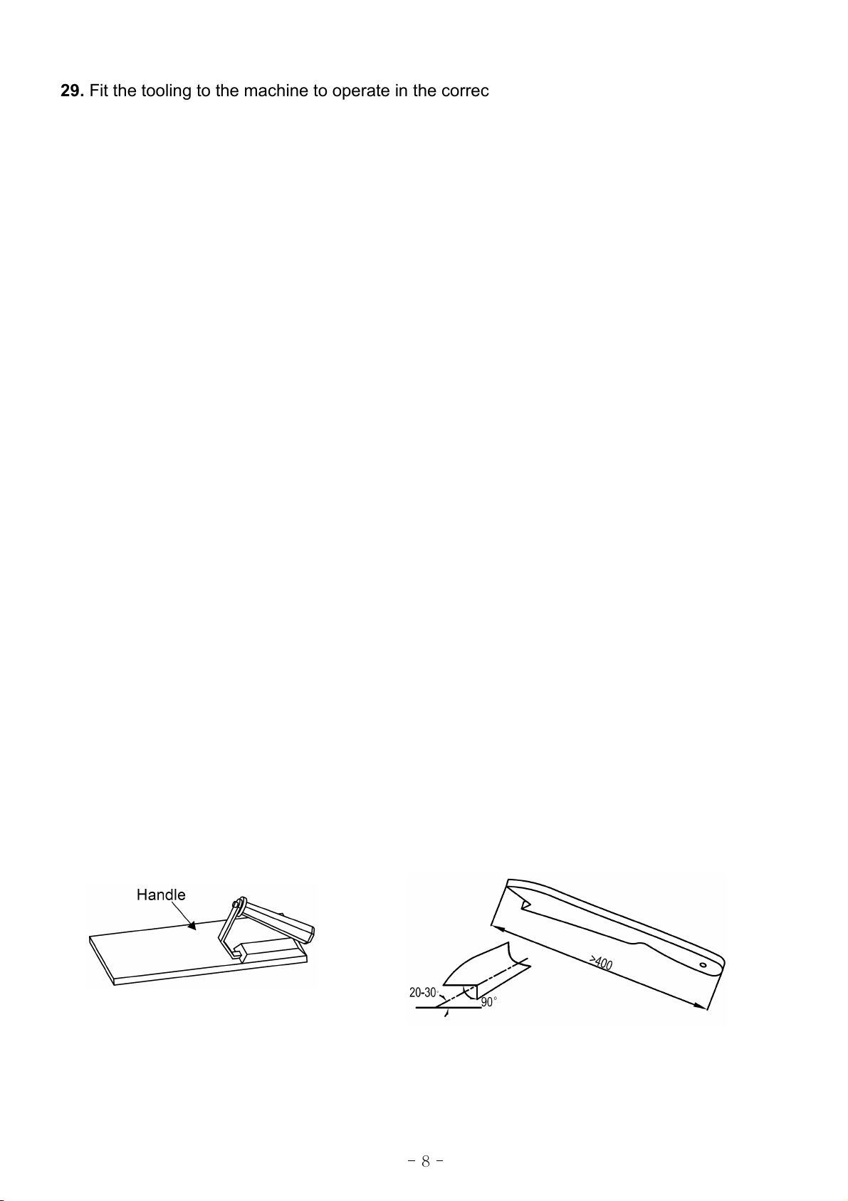
22. Push blocks or push sticks shall be used in circumstances where it is necessary to push the
workpiece against the fence.
23. Avoid awkward operations and hand positions where a sudden slip could cause your hand to
move into the spinning blade.
24. The machine shall be connected to an external chip and dust extraction system; the dust
extraction equipment is to be switched on before commencing machining.
25. Period check the brake function to make sure the stop time of the saw blade is less than 10s.
26. Only tools suitable for hand feed machines, conforming to EN 847-1 and EN 847-2:2013 and
marked MAN shall be used in order to reduce severity of injuries and kickback speed.
27. When using milling tools with diameter ≥16 mm and circular saw-blades, they shall conform
to EN 847-1:2013 and EN 847-2:2013; tool holders shall conform to EN 847-3:2013; Shank
milling tools with cutting circle diameter lower than 16 mm can be used without restriction.
28. Use table rings or table insert to close the gap between the table and the spindle to a
minimum.

- 8 -
29. Fit the tooling to the machine to operate in the correct direction of rotation. Avoid injury when
on use of tool carriers and handling tools.
30. Don't misuse, foreseeable misuse includes, e.g. feeding small work-pieces without safety
appliance, mounting of a saw blade on the arbor instead of milling tools and feeding work-pieces
in the same direction as of the running tool (climb cutting).
31. When changing safety-related components, these components must meet the lifetime
standard (T10d according ISO 13849-1) which should be not lower than 20 years.
4.3 Residua Risks
1. Take precautions to reduce the hazard of inhalation of harmful dusts (e.g. wearing a dust
mask).
Information on factors that influence exposure to dust, including:
1) The level of tool and machine maintenance
2) The material being machined
3) The importance of local extraction (capture at source),
4) The proper adjustment of hoods/baffles/chutes
) The external chips and dust extraction system connected t the machine need to comply with
the parameters stated in this instruction for use.
2. Wear ear protection to prevent hearing loss.
Instructions on factors that influence exposure to noise, including:
1) The correct choice of tools
2) The correct speed selection
3) The tools and machine maintenance
4) The type of material being machined
) The use of any accessories provided
6) The use of ear protection
3. Always wear safety glasses, also use a face or dust mask if cutting operation is dusty.
4. Protect against the hazard of being cut when handling cutters into the machine or doing
maintenance.
. Do not try to remove chips while the cutter is running and the shaper unit is not in the rest
position.
6. Do not try to use the machine unless all of the guards and other safety devices necessary for
the particular operation are in good working order.
7. In case of power supply failure, the tool may rotate for more than maximum run-down time.
4.4 Safety Equipment
A push block
(Fig.3)
and A push stick
(Fig.4)
must be used
Fig.3
Fig.4

- 9 -
4.5 Safety Labe s on the Machine
Here below you will find the warning labels that are attached to the machine and illustrated in the
instruction.(see
Fig.
)
Fig.
1.
Warning for residual risks
(Fig. -1)
Fig. -1 Fig. -2
2. Specific Safety Instructions for Shaper.
(Fig. -2)
3. Caution!
All electrical operation and maintenance shall be done by qualified electricians!
All electrical operation must be carried out in according to electrical instruction!
Fig. -3 Fig. -4
4. Warning for the motor cover opening.
(Fig. -4)

- 10 -
. Warning for the choice of tools & speed.
(Fig. - )
Fig. -
6. Warning for the cutter rotation direction.
(Fig. -6)
Fig. -6
7. Warning for the fence using.
(Fig. -7)
Fig. -7

- 11 -
4.6 Safety Devices
Every time, before you operate the machine, you must check if the Disconnect switch,
Emergent stop buttons, Inter ocking switches is in order.
When you set up, operate or service the machine , you must pay high attention to avoid the
potential dangers.
Encountering the event of accident or breakdown, you must press the Emergent stop buttons,
and turn the disconnect switch to cut the power.
Fig.6
Disconnect switch:
Interval:8 hours
Position:As
Fig.6
Operation: Turn the switch;
Emergent stop buttons:
Interval:8 hours
Position:2 emergency stop buttons are separately located, as
Fig.6.
Operation:Press the emergent stop buttons when emergency.
Interlocking switch
Interval:8 hours
Position:As
Fig.6
Operation:When open the cover, the motor power will be off.
Emergent stop buttons are prohibited to act as normal stop function.

- 12 -
5. Insta ation of the Machine
5.1 Transportation of Machines
5.1.1 Transportation and storage
This machine has been well packaged and rust preventive measures have been taken at the
factory. Care should still be taken to insure that no damage comes from rough handling while
moving. Ambient temperatures of -10 to 130 ℉ (-2 to ℃) can be endured by this machine.
Be careful not to expose this machine to rain or other severe weather.
●
Whi e transporting or hand ing the machine, be carefu and et the activity be done by
qua ified personne especia y trained for this kind of activity!
●
Whi e the machine is being oaded or un oaded, make sure that no person or subject
gets pressed by the machine!
●
Se ect proper transportation device according to the weight of the machine.
●
Make sure the ifting capacity of transportation device is competent for the weight of
the machine.
5.1.2 Transportation before unpacking
This machine is packed in a robust wooden crate.
Fig. 7
shows the device which can be used to
transport the packed crate.
Fig.7
5.1.3 Confirmation after unpacking
When open the packing box, please pay attention to the following items. If you have any
questions, please contact us..
1) Has the machine been damaged in transportation?
2) All accessories and documents are included with the machine.
3) The product is consistent with the contract.
2) The specifications on the machine label are consistent with the contract.
5.1.4 Transportation after unpacking
When transport the machine with a folk lift, firstly find the center of gravity of the machine,
insert the fork below the machine and then lift carefully.

- 13 -
5.2 Unpacking
Your machine was carefully packaged for safe transportation. Remove the packaging materials
from around your machine and inspect it. If you discover that the machine is damaged, please
immediately call Customer Service for advice. Save the containers and all packing materials for
possible inspection by the carrier or its agent. Otherwise, filing a freight claim can be difficult.
.2.1 Machine box contents
Fig.8
.2.2 Crosscut fence box contents
Fig.9
5.3 Safety Measure before Insta ation
Foundation p an
(
Fig.10
)
Space Requirements
(
Fig.11
)
Fig.10 Fig.11
Machine Box Contents:
Qty
A. Main unit
1
B. Crosscut tabl
e
1
C. Fence Assembly
1
D.
Cover
1
E.
Control Panel
1
F.
Bracket for control panel
1
Crosscut Fence
Box Contents:
Qty
A1.Stop Plate
2
B1. Cross
-
cutting
Fence
1
C1.
Support Bar
1
D1.
Handle
2

- 14 -
5.4 Insta ation
5.4.1 Positioning the base unit
This unit is very heavy, serious persona injury may happen if safe moving methods are
no fo owed! To be safe, you need assistance and power equipment when moving the
shipping crate and the machine!
Do not connect machine to electricity before installation is completed!
Main base is mounted at the wooden pallet with three bolts, take out these bolts, separate the
main base from the wooden pallet and move the main base to suitable place.
F oor required:
(See Fig.10)
The floor must have enough loading strength for the machine weight and should be flat and level.
If necessary, fix the machine to the floor with three bolts according the foundation plan
(Fig.10).
Space required:
(see Fig.11)
The machine should be placed at least 800 mm away from the wall.
When the main base is placed, screw the bolts A to touch the ground, then lock it.
(See Fig.12)
Fig.12 Fig.13
5.4.2. Fence assemb y insta ation
1) Mount the guide block to the table.
(Fig.13)
2) Install the fence by placing the main fence (A) on the table surface.
(See Fig.14)
3) Lock the fence to the table by threading the two locking handles(B) into the holes in the table
located behind the spindle.
(See Fig.14)
4) Attach the Guard Mounting Bracket (E) to the red top cover(C), then mount the bar and side
guard(F). (
See Fig.1 )
) Use the two locking handles (D) to lock the red top cover(C).(
See Fig.1 )
Fig.14 Fig.1

- 15 -
5.4.3 Cross-cut tab e insta ation
a. Slide the crosscut table into the T-slot on the side of the sliding table.
b. Align the screw shaft (B) on the swing arm to the hole on the bottom of crosscut table support,
and adjust the screws (C) and (D) to keep the surface of the crosscut table parallel to the surface
of the sliding table, then tighten the screws (C) and (D). Lock the crosscut table with handle A,
(see
Fig.16).
Fig.16
Fig.17 Fig.18
c. Install the crosscut fence into two positioning holes on the crosscut table (
Fig.16)
. Lock the
fence to the crosscut table by turning the knobs (J) and (E), release the knob (E), you can swing
the fence and lock it in any angle (±4 degree) with the locking knob (E), see
Fig.17
.
d. The knob (F) can be used to quick lock the fence to 90 degree, see
Fig.18.
There is a lock block (G) at the bottom of the fence, you can lock or release the fence by turning
the knob (F) quickly. You can adjust the fence stop position by releasing the nut (I) and turning
the screw (H) in or out,
5.4.4 Insta the touch screen bracket
1. Install the bracket(A) to the main cabinet with four M10X2 cap screws(B), as
Fig.19.
Fig.19 Fig.20

- 16 -
2. Install and lock the touch screen by turning the locking knob, as shown in
Fig.20,
3. Plug the ports "A", "B", "C" and "D" into the corresponding sockets, as
Fig.21
Fig.21 Fig.22
5.4.5. Back cover insta ation
Slide the back cover onto the hinges which are pointed in
Fig.22
, then lock the door with the
screws on the other side.
5.4.6 Connecting the extraction system
Dust collection device should be prepared by customer.
The dust collection equipment needs to be switched on before start the machine;
Fig.23
The outlet diameter of port A is 100mm, see
Fig.23
The outlet diameter of port B is 100mm, see
Fig.23
The required air speed is 20m/s for vacuum dust collector. The air speed of dust collector device
(in accordance with EN 12779:2004) should not lower than 20m/s to ensure that the dust from
the machine can be exhausted. User must wear dust-proof mask.
Required air flow:1 00 m³/h;

- 17 -
5.4.7 E ectrica insta ation
Wiring should only be done by professional electricians.
All wirings in the cabinets should be protected against the direct contact and at least
meet the standard of IP2X when finishing electrical installation.
All the exposed conductive parts should be connected to the protective bonding circuit.
Close and lock the door of cabinet, take off the keys and keep them well stored after
finishing installation.
There should be enough space around the machine and the cabinets for convenient
maintenance.
The machine should be installed in a workshop with good illumination and ventilation.
Over-voltage protection device should be provided by end user on spot.
Entrust this operation to qualified personnel. Always make sure the machine is properly
grounded.
Check that if the voltage and frequency which are shown on the machine’s name plate is
corresponded to the electric power supply voltage and frequency you will use for the machine.
The circuit breaker (16A) with RCD module (30mA) shall be installed for supplying electric power
to this machine, in order to protect operator against electrical shock caused by indirect shock
Wiring:
Complete the electrical connection according to the electrical drawings.
The wirings on the spot should be referred to the requirements of Clause 13 (Wring practices) of
EN 60204-1:2006.
Checking:
After finishing wiring on the spot, check the following items at least:
Check the wirings of machine.
Check the direction of motors and change wiring if necessary.
Check the components for defects, such as loosening or damages.
Check the functions of safety devices (such as interlocked guards and emergent stop buttons).
Check the direction of motors and change the phases if necessary.
Check the functions of all limited switches.
The termina s are marked L1,L2,L3,N,PE

- 18 -
ELECTRICAL CONNECTIONS
Table of contents
Other HARVEY Industrial Equipment manuals