HARVEY HW303 User manual


1
Contents
1.Foreword.................................................................................................................................................................................. 2
2.Warranty Information............................................................................................................................................................2
3.Machine Description............................................................................................................................................................. 3
3.1 Feature Identification................................................................................................................................................... 3
3.2 Product Specifications.................................................................................................................................................3
3.3 Intended Use.................................................................................................................................................................4
3.4 Dimensions and Weight.............................................................................................................................................. 4
3.5 Electrical Po er Requirements..................................................................................................................................4
4.Safety Regu ations................................................................................................................................................................ 5
4.1 General Safety Instructions........................................................................................................................................ 5
4.2 Specific Safety Instructions for Shaper.....................................................................................................................5
4.3 Residual Risks..............................................................................................................................................................6
4.4 Safety Devices..............................................................................................................................................................6
5.Insta ation of the Machine..................................................................................................................................................7
5.1 Transportation of the Machine................................................................................................................................... 7
5.2 Unpacking..................................................................................................................................................................... 7
5.3 Safety Measures before Use/Installation................................................................................................................. 8
5.4 Installation..................................................................................................................................................................... 9
6.Operations.............................................................................................................................................................................15
6.1 Using the Control Panel............................................................................................................................................15
6.2 Adjusting the Arbor Height....................................................................................................................................... 15
6.3 Change the Speed Range........................................................................................................................................16
6.4 Cutter Installation....................................................................................................................................................... 17
6.5 Adjusting and Using the Fence................................................................................................................................18
6.6 Using the Starting Pin............................................................................................................................................... 19
7.Maintenance..........................................................................................................................................................................19
8.Exp oded View and Parts List.......................................................................................................................................... 20
9.Dec aration and Conformity............................................................................................................................................. 28

2
1. Foreword
This manual contains basic information for qualified
operating staff and describes the surroundings and
using ays of the machine for those it is intended. It
contains also all necessary information for a correct
and safe operating. The machine is equipped ith
various safety equipment protecting operator and
machines ell at usual technological using. These
regulations, ho ever, cannot sheet all other safety
aspects. That is hy operator must peruse and
make sense of this manual before starting of
machine use. Installation and operation mistakes
ill be foreclosed here ith.
Do not try to start the machine before having read
all instructions manual delivered ith the machine
and understood every function and technique.
2. Warranty Information
Limited Warranty
T o year
Proof of Purchase
Please keep your dated proof of purchase for
arranty and servicing purposes.
Limited Too Warranty
We makes every effort to ensure that this product
meets high quality and durability standards. e
arrants to the original retail consumer a 1-year
limited arranty as of the date the product as
purchased at retail and that each product is free
from defects in materials. Warranty does not apply
to defects due directly or indirectly to misuse, abuse,
normal ear and tear, negligence or accidents,
repairs done by an unauthorized service center,
alterations and lack of maintenance. e shall in no
event be liable for death, injuries to persons or
property or for incidental, special or consequential
damages arising from the use of our products. To
take advantage of this limited arranty, return the
product at your expense together ith your dated
proof of purchase to us.
Notice to California Residents: This product can
expose you to ood dust, hich is kno n to the
State of California to cause cancer. For more
information, go to .P65Warnings.ca.gov.

3
3. Machine Description
3.1 Feature Identification
Fig.1
A. Cabinet
B. Lock Handle
C. Main Table
D. Fence Assembly
E. Control Panel
F. Miter Gauge
G. Extension Table
H. Scale
I. Raise/Lo er Hand heel
3.2 Product Specifications
Note:
For different areas, it differs in parameter con
figuration, the actual object shall prevail.See
the equipment nameplate for details
Every machine e produced is fitted ith a name
plate ith its serial number. An exact description of
the machine model and serial number ill facilitate
rapid and effective replies from our after-sales
service.
The European & Asian Area:
Table size 780mmx725mm
( ith extension)
Table height: 860mm
Insert 60mm,70mm,100mm,140mm
Spindle size: 35mm
5/4" & 3/4"
Spindle speed 1400/3000/7000/9000 rpm
Capacity under nut 140mm
Spindle travel 100mm
Dust port 100mm
Miter slots 19.05x9.525mm
Router bit 8mm & 12mm
1/4" & 1/2"
Belt V-belt
Motor 3HP/230V/50Hz/1PH 13.9A
3kW/380V/50Hz/1PH 6.5A
Footprint: 590mmX530mm
Note:
For the European market, the motor is equipped
ith brakes
North American Area:
Table size 31"×28-1/2"
( ith extension)
Table height: 34"
Insert 2-1/8",2-3/4",4",5-1/2"
Spindle size: 5/4" & 3/4"
Spindle speed 1700/3600/8500/11000 rpm
Capacity under nut 2-1/2" (Spindle size 3/4")
5-1/2" (Spindle size 5/4")
Spindle travel 4"
Dust port 4"
Miter slots 3/4"×3/8"
Router bit 1/4" & 1/2"
Belt V-belt
Motor 3HP/230V/60Hz/1PH 13A
Footprint: 23-1/4"×20-3/4"

4
3.3 Intended Use
1. Purpose of the Machine
The machine enables semi-finished products made
of ood or materials based on ood to be milled
ith a spindle
The machine is designed for operation performed
by one orker only.
The machine must not be handled by children and
youngsters in any manner.
2. Worker Qua ifications
Only expert skilled in the field of ood-machining or
a orker instructed and trained by such expert may
operate the machine, regardless of the sex. While
orking on the machine, the operator must get
familiar ith these instructions and comply ith any
safety rules, regulations and provisions in force in
the respective country.
3. Working Environment
The machine must be operated in a orkshop
environment, complying the environment
classification danger of inflammable dust fire
(BE2N2), the temperature of hich does not exceed
+40°C and does not drop belo +5°C, the relative
humidity of air is from 30% to 95% non-condensing,
the height above the sea level is up to 1000m.
4. Machine Operator Positions
The shaper is intended to be operated from the
position as Fig.2 sho n.
Fig.2
3.4 Dimensions and Weights
Model Package Net/Gross
(Kg)
Dimension
(mm)
HW303
Main
Machine 190/207 840x760x1020
(
H
)
Fence 22/25 845x455x250(H)
3.5 Requirements of e ectrica power
List of the motor using & pre- ired voltage:
Item Motor
2.2kW(3HP)
Voltage 230V
Phase 1-Phase
Freq. 50Hz 60Hz
Nominal current 13.9A 13A
Pre- ired 230V/1Ph
Cords 3
Circuit Breaker 20A
Item Motor
3kW(4HP)
Voltage 380V
Phase 3-Phase
Freq. 50Hz
Nominal current 6.5A
Pre- ired 380V/3Ph
Cords 5
Circuit Breaker 10A
To avoid the accidental injury and damage to the
machine, please check the name plate of the
machine carefully to identify the po er supply
demand of the machine.

5
4. Safety Regu ations
4.1 Genera Safety Instructions
1. KNOW YOUR MACHINE.
Read and understand the o ner manual and labels
affixed to the machine. Learn its application and
limitations as ell as its specific potential hazards;
2. GROUND THE MACHINE.
In the event of the electrical short, grounding
reduces the risk of electrical short;
3. KEEP GUARDS IN PLACE.
Keep in good orking order, properly adjusted and
aligned;
4. REMOVE ADJUSTING KEYS AND
WRENCHES.
Form habit of checking to see that keys and
adjusting renches are removed from machine
before turning it on;
5. KEEP WORK AREA CLEAN.
The orking floor area around the machine should
be leveled and kept ell-maintained, unobstructed
and free from loose material, e.g. chips and off-cuts;
6. AVOID DANGEROUS ENVIRONMENT.
Don’t use machines in damp or et locations or
expose them to rain. Keep ork area ell lit and
provide adequate surrounding ork space;
7. KEEPCHILDREN AWAY.
All visitors should be kept a safe distance from ork
area;
8. MAKE WORKSHOP CHILD-PROOF.
With padlocks, master s itches or by removing
starter keys;
9. USE PROPER SPEED.
A machine ill do a better and safer job hen
operated at the proper speed;
10. USE RIGHT MACHINE.
Don’t force the machine or the attachment to do a
job for hich it as not designed;
11. WEAR PROPER APPAREL.
Do not ear loose clothing, gloves, neckties or
je elry (rings, atch) because they could get
caught in moving parts. Non-slip foot ear is
recommended. Wear protective hair covering to
contain long hair. Roll up long sleeves above the
elbo s;
12. DON’T OVER REACH.
Keep proper footing and balance at all times;
13. MAINTAIN MACHINE WITH CARE.
Keep tools sharp and clean for best and safest
performance. Follo instructions for lubricating and
changing accessories;
14. DISCONNECT MACHINES.
Before servicing, hen changing accessories or
attachments;
15. AVOID ACCIDENTAL STARTING.
Make sure the s itch is in the ‘’OFF’ ’position before
plugging in;
16. USE RECOMMENDED ACCESSORIES.
Consult the manual for recommended accessories.
Follo the instructions that accompany the
accessories. The use of improper accessories may
cause hazards;
17. NEVER STAND ON MACHINE.
Serious injury could occur if the machine tips over.
18. CHECK DAMAGED PARTS.
Before further use of the machine, a guard or other
parts that are damaged should be carefully checked
to ensure that they ill operate properly and
perform their intended function.
19. NEVER LEAVE MACHINE RUNNING
UNATTENDED.
Turn po er off. Don’t leave any machine running
until it comes to a complete stop;
20. LIGHTING SHALL BE PROVIDED.
Adequate general or localized lighting shall be
provided.
4.2 Specific Safety Instructions for Shaper
1. Serious personal injury may occur if normal
safety precautions are overlooked or ignored.
Accidents are frequently caused by lack of
familiarity or failure to pay attention. Obtain advice
from supervisor, instructor, or another qualified
individual ho is familiar ith this machine and its
operations.
2. All electrical connections and iring should be
made by qualified personnel only.
3. To reduce the risk of electrical shock. Do not use
this machine outdoors. Do not expose to rain or
moisture, store indoors in a dry area.
4. Stop using this machine, if at any time you
experience difficulties in performing any operation.
Contact your supervisor, instructor or machine
service center immediately. Reporting of faults or
defects in the machine, including guards or tools, as
soon as they are discovered.
5. Do not leave the unit plugged into the electrical
outlet. Unplug the unit from the outlet hen not in
use and before servicing, performing maintenance
tasks, or cleaning.
6. Al ays turn the po er s itch “OFF” before
unplugging the shaper.

6
7. Do not use the shaper as a toy. Do not use near
or around children.
8. Keep hands a ay from cutting tool.
9. Never run stock bet een the fence and the
cutter.
10. Al ays use a miter gauge and clamp
attachment hen shaping small pieces. The fence
should be removed during this operation.
11. Al ays feed against the rotation of the cutter.
12. Work-piece to be adequately supported during
machining/feeding using, here necessary,
additional support, e.g. for long ork-pieces.
13. Keep cutters sharp and free from rust and pitch,
follo ing tool manufacturers’ instructions for use,
adjustment and repair of tools.
14. Only use flat orkpieces in the shaper, never
use arped or t isted lumber.
15. Never take off too much material in one pass.
Make several lighter passes.
16. Set up operations henever possible to have
the cutters under the orkpiece, al ays use proper
speed setting for the cutter being used.
17. Not removing any splinters or other part of the
ork-piece from the cutting area hile the machine
is running.
18. Ensure the maximum rotational speed marked
on the tools is not exceeded.
19. Make sure cutters are properly secured before
starting shaper.
20. Use guards, guides, and hold-do n herever
possible, not using the machine unless the guards
and other safety devices necessary for machining
are in position, in good orking order and properly
maintained.
21. Do not perform any operation freehand. Use the
fence for straight shaping.
22. Push blocks or push sticks shall be used in
circumstances here it is necessary to push the
orkpiece against the fence.
23. Avoid a k ard operations and hand positions
here a sudden slip could cause your hand to move
into the spinning blade.
24. The machine shall be connected to an external
chip and dust extraction system; the dust extraction
equipment is to be s itched on before commencing
machining.
25. Period check the brake function to make sure
the stop time of the sa blade is less than 10s.
26. Only tools suitable for hand feed machines,
conforming to EN 847-1 and EN 847-2:2013 and
marked MAN shall be used in order to reduce
severity of injuries and kickback speed.
27. When using milling tools ith diameter ≥16 mm
and circular sa -blades, they shall conform to EN
847-1:2013 and EN 847-2:2013; tool holders shall
conform to EN 847-3:2013; Shank milling tools ith
cutting circle diameter lo er than 16 mm can be
used ithout restriction.
28. Use table rings or table insert to close the gap
bet een the table and the spindle to a minimum.
29. Fit the tooling to the machine to operate in the
correct direction of rotation. Avoid injury hen on
use of tool carriers and handling tools.
30. Don't misuse, foreseeable misuse includes, e.g.
feeding small ork-pieces ithout safety appliance,
mounting of a sa blade on the arbor instead of
milling tools and feeding ork-pieces in the same
direction as of the running tool (climb cutting).
4.3 Residua Risks
1. Take precautions to reduce the hazard of
inhalation of harmful dusts (e.g. earing a dust
mask);
2. Wear ear protection to prevent hearing loss;
3. Al ays ear safety glasses. also use a face or
dust mask if cutting operation is dusty;
4. Against the hazard of cutting hen handling
cutters into the machine or doing maintenance;
5. Not to try removing chips hilst the cutter (s) is
(are) running and the shaper unit(s) is (are) not in
the rest position;
6. Not to try using the machine unless all of the
guards and other safety devices necessary for
machining are in good orking order;
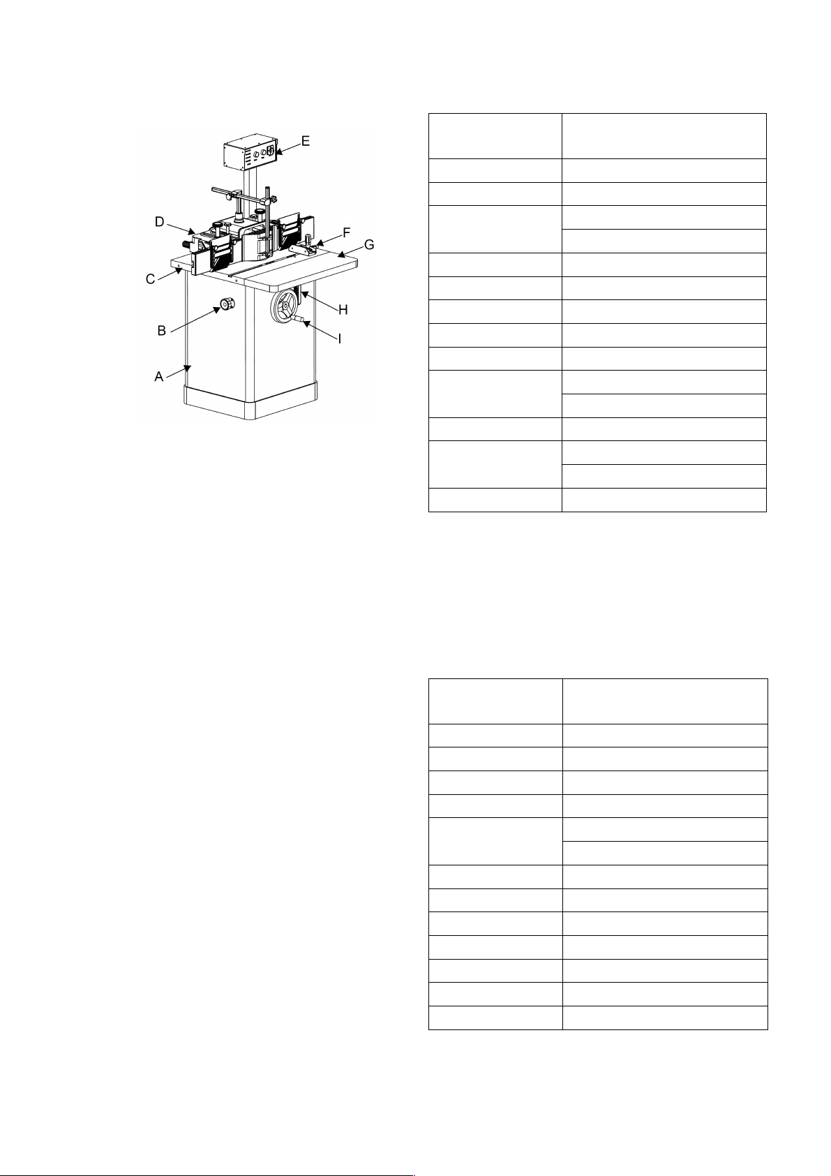
4.4 Safety Equipment
To prevent your hands being close to the cutter, a
push block (Fig.3) or push stick (Fig.4) must be
used hen cutting small or narro stock.
Fig. 3
Fig. 4

7
5. Insta ation of the Machine
5.1 Transportation and storage
While transporting or handling the machine, be
careful and let the activity be done by qualified
personnel especially trained for this kind of activity!
While the machine is being loaded or unloaded,
make sure that no person or subject gets pressed
by the machine! Fig. 7 sho s the device hich can
be used to transport the packed crate. Ambient
temperatures of -25 to 55
℃
can be endured by this
machine.Be careful not to expose this machine to
rain or other severe eather.
Fig. 5
5.2 Unpacking
This product includes t o packages: Machine box
and Fence box.
Please check the shipping content according to
Fig.6, Fig.7, Fig 8-1 or Fig.8-2 and belo list.
NOTE: If you can't find an item on this list, check the
mounting locations or examine the packaging
materials carefully. Occasionally e pre-install
certain components for shipping purposes.
Remark
:
1. Fig.8-2 is only for North American area.
Fig.8-1 is only for European & Asian area.
2. The parts sho n in Fig.7 & Fig.8-1 or Fig.8-2
are placed in the Accessory Package hich
can be found in the cabinet.
3. Part D is placed in the cabinet, and Part C is
placed on the pallet.
4. For some specific regions, the configuration
may be slightly different, Goods in kind prevail.
Machine Box
:
Fig. 6
A: Main Unit
B: Extension Table
C: Control Panel Bracket
D: Control Panel
Fig. 7
E1: Table Insert
(
130mm
)
E2: Miter Gauge
E3: Push Handle
E4: Hand heel Handle
E5: Hex Wrench
(
1.5-8mm
)
E6: Open End Wrench
(
10-12
)
E7: Open End Wrench
(
14-17
)
E8: Open End Wrench
(
30-32
)
E9: Open End Wrench
(
51
)

8
Fig. 8-1
Fig. 8-2
F1: Router Collet
(
8mm & 12mm
)
F2: Spindle Assembly
(
35mm
)
F3: Dra Bar
(
2 PCS
)
F4: Router Collet
(
1/4inch & 1/2inch
)
F5: Spindle Assembly
(
5/4 inch
)
F6: Spindle Assembly
(
3/4 inch
)
F7: Dra Bar
(
3 PCS
)
Fence Box
:
Fig. 9
G: Transparent Guard (6 inch )
H: Transparent Guard (3.5 inch)
I: Fence Assemb y
5.3 Requirements for space and f oor
Please make sure that the machine is placed at
least 800 mm a ay from the all.
The floor should be flat and level.

9
5.4 Insta ation
5.4.1 Remove the Pa et
The machine is fixed on the pallet by M8 hex bolts.
Before installing, please take off the motor cover (B)
sho n in Fig. 11, and remove the moveable parts in
the cabinet. Then move the machine out after
removing the set bolts under the pallet, as sho n in
Fig. 10. Locate the machine at appropriate place
ithout fixing.
NOTE
:
The machine is very heavy, serious
persona injury may happen without the
assistance of ifting machine.
Fig. 10
5.4.2 Insta ation of the Motor Cover, Extension
Tab e and Handwhee Hand e (Fig. 11)
a. Remove the yello motor transport belt (A)
。
The be t shou d be kept for future transport.
b. Remount the motor cover(B).
Some standard fasteners of the motor cover are
p aced on the motor cover.
c. Install the extension table (C) as sho n in Fig.11
(The standard fasteners are pre-mounted on the
main table)
The extension tab e shou d be eve ed with the
main tab e top. If the eve can’t be adjusted, you
can post crepe paper on the junction side to do
a adjustment.
d. Install the Hand heel Handle (D)
Fig. 11
5.4.3 Insta ation of the Contro Pane
As sho n in Fig.12, install the control panel as
follo s:
a. Mount the control panel to the bracket by using 4
sets of cap scre s hich are pre-mounted on the
control panel.
b. Mount the bracket to the the table by using 2 sets
of cap scre s hich are pre-mounted on the
table.
Fig. 12

10
5.4.4 Insta ation of Spind e and Router Co ect
The machine is equipped with spind e and
router co ect, and their insta ation methods are
same. However, the spind e specifications
differs in different areas, you need to check if
the specification of the spind e you get
coincides with the description in this manua .
a. Remove the table insert pre-installed on the
table for future use.
b. Remove the collar and gland pre-installed on the
arbor as sho n in Fig. 13. Mount the spindle (A) to
the arbor. The key slot need to be engaged ith the
key on the arbor, then rotate the spindle left and
right to make the conical surfaces fully fit.
Note: The co ar removed in this step is a
precision part, p ease keep it carefu y, avoid
any bumping and rusting.
c. Insert the dra bar (B) through the arbor, and
rotate it into the threaded hole underneath the
spindle. Lock the steps underneath the spindle by
using the provided 51 rench and tighten the
locking nub (C), as sho n in Fig. 13.
(The 51&17 renches need to be used in this step.)
d. After the spindle being fully locked, use a dial
gauge to check the runout of the spindle top (<0.1
mm). If the runout is belo the standard(<0.1 mm),
loosen the nut (C) and repeat step b & c until the
standard is reached.
Fig. 13
5.4.5 Insta ation and adjustment of tab e insert
The machine is equipped ith 2 sets of table inserts:
(
A1+A2+A3
)
& B
A1:Inner Diameter 100mm(4”), can be installed on
the table directly.
A2:Inner Diameter 70mm(2-3/4”), need to be
pressed into A1 for use.
A3:Inner Diameter 60mm(2-1/8”), need to be
pressed into A1 for use.
B: Inner Diameter 130mm(5-1/8”), can be installed
on the table directly.
Note
:
The aperture of the tab e is 140mm(5-1/2”).
Without the insta ation of tab e insert, the
maximum diameter of the cutter that can be
insta ed and used is up to 140mm(5-1/2”).
1. Fix the table insert to the table by inserting the
bolt (C) through the bolt (D), as sho n in Fig. 14;
the table insert should be coplanar ith the cast iron
table, the height of table insert can be adjusted by
rotate the bolt (D) clock ise or counterclock ise
ith a hex rench.
2. As sho n in Fig. 14, the starting pin is used for
free routing. It can be used by being inserted on the
table insert A1 ith three alternative positions.
Note: Make sure the p ay between the cutter and
tab e is minimum, which can great y improve the
routing safety. It’s a so very important to chose
appropriate tab e insert according to the cutter.
Fig. 14

11
5.4.6 Insta ing the Fence
a. Place the cast iron fence body (A) on the main
table and fix it to the table by using the locking
handle (B), as sho n in Fig. 15.
Note: There are two sets of mounting ho es for
mounting the fence vertica y or horizonta y.
Fig. 15
b. Mount the red guard (C) to the cast iron fence
body and lock it by using the knob (D), as sho n in
Fig. 16.
c. Mount the fixture (E) to the red guard (C), then
install the guard fixing level and side guard (F), as
sho n in Fig. 16.
Fig. 16
5.4.7 Insta ing the Overhead Guard
For the safety of free routing, a overhead guard
must be used. This machine is equipped ith the
overhead guard, as sho n in Fig. 17. There are t o
specifications of the transparent guards for you
choosing as needed.
A: 6 inch.
B: 3.5 inch.
Fig. 17
5.4.8 Connect with the Dust Co ection System
For the safety and optimal performance, the
machine must be connected ith dust collection
system.
The dust port of this machine is placed on the fence
guard ith diameter of 100mm(4”), as sho n in
Fig.15
Recommended air flo : 600 m³/h (350CFM)
Note: The dust co ector device shou d be
prepared by customer. The air f ow of dust
co ector shou d be higher than 22 m/s at east
to ensure that the dust produced by machine
can be c eaned time y.
A ways start the dust co ector before starting
the machine.

12
5.4.9 E ectrica Insta ation
Provide the po er supply according to Chapter 3.5.
Wiring shou d on y be done by professiona
e ectricians.
A ways make sure the machine is proper y
grounded. A exposed conductive parts shou d
be connected to the protective ground circuit.
An over-vo tage protection device shou d be
provided by end user.
The circuit breaker sha be insta ed to supp y
e ectric power to this machine, in order to
protect peop e against e ectrica shock due to
incidenta contact.
Check that the voltage and frequency required by
the machine, hich is sho n on the machine’s
name plate, correspond to the electric po er supply
voltage and frequency.
Ensure IP54 protection class for the incoming cable
hen the finished installation is in place.
For single-phase motor, the equipment is equipped
ith a plug.
For there-phase motor,only po er cables are
reserved.
Checking:
After finishing iring, check the follo ing items at
least:
1. Check the external iring for compliance ith
safety requirements.
2. Check the rotating direction of arbor.
3. Check the functions of safety devices (such as
interlocked guards and emergent stop buttons).

13
ELECTRICAL CONNECTIONS:
220V / 1-Phase

14
380V / 3-Phase
Without Brake circuit board
With Brake circuit board

15
6. Operations
6.1 Using the Contro Pane
(
Fig. 18
)
Fig. 18
A: Start Button
B: Stop Button
C: Rotation Direction S itch Button
E1: Arbor Speed Indicator-1400rpm (50Hz)
Arbor Speed Indicator-1700rpm (60Hz)
E2: Arbor Speed Indicator-3000rpm (50Hz)
Arbor Speed Indicator-3600rpm (60Hz)
E3: Arbor Speed Indicator-7000rpm (50Hz)
Arbor Speed Indicator-8500rpm (60Hz)
E4: Arbor Speed Indicator-9000rpm (50Hz)
Arbor Speed Indicator-11000rpm (60Hz)
D: Rotation Direction Indicator. When this indicator
is on, it means that the rotation direction no is
clock ise, please operate carefully.
Warning:
1. Do not start the switch unti a insta ation
and debugging is comp eted!
2. The rotation direction of the arbor is
counterc ockwise in norma state. If the arbor is
rotating c ockwise, specia care shou d be taken
during operation to avoid accidenta injury.
6.2 Adjusting and Locking the Arbor Height (Fig.
19)
A: Height Adjustment Hand heel-- Adjust the arbor
height.
B: Arbor Locking Handle-- Lock the arbor.
C: Height Scale-- Sho the arbor height.
Note:
1. The arbor ocking hand e must be re eased
during adjusting arbor height and shou d be
ocked tight y after finishing the adjustment.
2. Open the back cover of machine, you can
adjust the position of the sca e indicator. The
indicator on y shows the position of the arbor
approximate y, if you want to adjust the arbor
accurate y, you may need assistant measuring
too s further.
Fig. 19

16
6.3 Adjusting the Speed
1. There are four speed ranges for this machine
(they differ in 50Hz and 60Hz). Open the back cover
of machine, the speed can be changed by adjusting
the belt position. The speeds corresponding to the
belt positions are sho n in Fig. 20.
Fig. 20
2. The belt has been adjusted in factory. After using
for long time, adjusting position or replacing the
arbor assembly, the belt may become too tight or
loose, so you need to adjust the belt tension no .
Check tension by pushing ith moderate pressure
on the belt half ay and the adequately tensioned
belt ill deflect about 6mm(1/4”), as sho n in Fig.
21.
Adjustment Method: Loose the bolt (C), adjust the
belt tension by pushing the motor left and right, then
lock the bolt (C), as sho n in Fig. 21.
Fig. 21
Note: When rep acing the arbor assemb y (D),
you need to pu out the safety pin (E) to prevent
the arbor f ying out accidenta y.
3. When operating the machine, the linear
speed should be controlled ithin the safe range
sho n in Fig. 22. Avoid using the linear speed in the
danger zone. (The diagram sho s the metric
system)
Fig. 22
Cutting speed is related to the ood properties,
cutter type and cutting types. The user can calculate
the approximate cutting speed based on the
follo ing formula:
Ca cu ating the Cutting Speed
:
The linear cutting speed should be selected from 40
m/s to 70 m/s to minimize the risk of kickback.
Cutting speed is related to the ood properties,
shapes and orker’s habits. The user can calculate
the approximate cutting speed based on the
follo ing formula:
V — Cutting speed (m/s)
b — Cutting height of ood (mm)
e1— Cutting thickness of ood (mm)
VH— Feeding speed (m/s)
P — Po er (k )
K — Unit cutting resistance (N/mm2)
Usually, the value K depends on the direction of the
ood fiber, the type of ood, the shape of the cutter
and so on. The K value can be ritten as the
follo ing formula:
Kc — The basic cutting coefficient re ated to the
cutting type:
Remark
:
Rip cutting means the cutter is parallel to
the ood grain direction, crosscutting means the
cutting is vertical to the ood grain direction.
Cutting
Type
Cutting Angle
45° 50° 60° 70° 80° 90°
End Grain
Cutting 1.75 2.1 2.5 3.5 4.4 5.3
Rip
Cutting 0.5 0.7 1 1.4 1.85 3
Cross
Cutting 0.3 0.31 0.33 0.35 0.45 0.6
P
vebK
V
H
⋅
⋅
⋅
=
1
Bogc
KKKKK
⋅
⋅
⋅
=

17
Kg — Resistance coefficient
Tree Species Kg Tree species Kg
Pine Tree 1 Birch 1.25
Spruce 1 Oak 1.7
Dahurian Larch 1.1 Beech 1.5
Poplar 0.85 Bass 0.8
Ko — The coefficient of the sharpness of cutter
Working Hour 0 1 1.5 2
Ko 1 1.2 1.25 1.3
Working Hour 3 4 5 6
Ko 1.4 1.5 1.6 1.7
KB—Coefficient of the wood humidity
Wood
state Humidity KBWood State Humidity KB
Very
dry 5-8% 1.1 Ne ly
Milled 50-70% 0.89
Dry 10-15% 1.0 Transported
in Water
>
70% 0.87
Air dry 20-30% 0.93
6.4 Cutter and Bit Insta ation
The cutter and bit can be installed on this machine,
please refer to the manual for detailed specification.
Allo ed Maximum Cutter or Bit Diameter: 140mm
(5-1/2”)
Allo ed Maximum Cutter or Bit Height: 140mm
(5-1/2”)
Insta ing the Cutter
:
Install the cutter in the spindle (A), as sho n in Fig.
23. The spindle is equipped ith the router collet (B)
of different thickness and the gland (C).
Use the 51mm Open End Wrench (E) to lock the
step underneath the spindle, then insert the hex
rench (F) and lock the spindle (D), as sho n in Fig.
24.
(In most cases, the Open End Wrench is used
belo the table, so you need to open the back cover
of machine before that.)
Fig. 23
Fig. 24
Note:
1. You must make sure that the g and is ocked
tight y and effective y, as shown in Fig.25..
Avoid insta ing the cutter as shown in Fig.
26. The tightening torque of the cap screw is
about 30 Nm.
2. For the maximum safety and best routing
performance, p ease insta the cutter
underneath the spind e as possib e as you
can (against the f ange face of the spind e
bottom).
Fig. 25

18
Fig. 26
Insta the Bit
:
The bit is the most commonly used and most
economical moulding cutter ith most types. The bit
is fixed by the router collet (F), and the router collet
(F) is fixed to the arbor by the dra bar (G), as
sho n in Fig. 27.
T o locking blocks (H1& H2) ith different
specifications are provided. Refer to the manual for
detailed specifications and choose as needed.
Fig. 27
6.5 Adjusting and Using the Fence Assemb y
There are t o individual fences in the fence
assembly, each of them can be adjusted and used
individually. As sho n in Fig. 28, by releasing the
locking level (A), the fence can be adjusted to the
cutter closely or far a ay from the cutter. You can
adjust the fence for ard and back ard by rotating
the handles (B). Each fence is equipped ith
individual position to sho the scale.
Fig. 28
Adjusting the Fence:
The fence is mounted on the fence holder (C). By
adjusting the four adjusting bolts (D) placed on the
fence holder, you can adjust the perpendicularity
bet een the fence and table and the parallelism
bet een t o fences.
The perpendicularity bet een the fence and table:
≤0.1mm(0.004”).
The parallelism bet een t o fences:
≤0.1mm(0.004”).
Note:
1. Before using the fence assemb y, a ways
check the perpendicu arity between the fence
and tab e and the para e ism between two
fences.
2. Before using the fence assemb y, a ways
make sure that a the knobs are secured tight y.

19
6.6 Using the Starting Pin
By using the starting pin provided ith the machine,
you can do the Free-hand routing, as sho n in Fig.
29. Free-hand routing takes a high degree of skill
and dexterity and is done ithout the protection and
aid from the fence and guard. The most dangerous
part of free-hand routing is beginning the cut, hen
the cutter first contacts the orkpiece. Often the
orkpiece ill tend to jerk or kickback, presenting
an injury hazard to the operator. The starting pin ill
allo you to anchor and slo ly pivot the orkpiece
into the cutter as the cut is started, making the
operation more stable and safe.
Fig. 29
Warning:
1. Free-hand routing great y increase chance
that the operator may ose contro of the
workpiece, which cou d resu t in serious
persona injury. Therefore, a starting pin or
other simi ar devices must be used.
2. A guard as shown in Fig. 17 must be used in
free-hand routing to prevent the accident injury
happening.
7.Maintenance
This machine requires very little maintenance other
than minor lubrication and cleaning.
Lubrication
The machine has sealed lubricated bearings in the
motor and the arbor assembly and ill not require
any additional lubrication.
Use a ire brush to clean off the ood dust on the
sliding block and apply premium grease to keep it
lubricated.
Lubricate once a eek.
C eaning
Vacuum excess ood chips and sa dust in the
cabinet timely.
Clean once a day.
Changing the Be ts
1. Check the belts regularly (monthly) to avoid any
grease or oil on the belts.,
2. Check the belts regularly (monthly) to see if the
tension is adequate or the belts are cracked. If the
belts are cracked, change them timely.
3.Change the belts regularly (yearly).
Note:
Make sure the power cord is disconnected from
the power source before changing be ts!
Start the machine to have a check after
changing the be ts. If the vibration or noise is
too big, the possib e reasons may be the too
tight or oose be ts or skewed motor position,
p ease re-tension the be ts or re-position the
motor. And re-check the be t tension after using
the machine for hours.
Table of contents
Other HARVEY Industrial Equipment manuals