harvst S24 User manual
Setup guide
Model S24
Greenhouse only, Solar, 3-season and 4-season versions
V2 / From Jan 2022
4-season model shown above
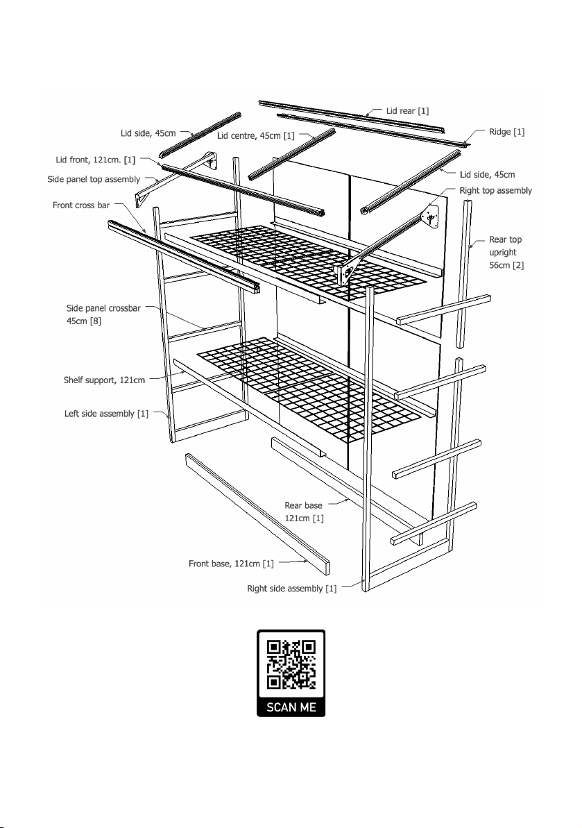
Exploded diagram
Visit www.harvst.co.uk/setup for more information, videos and photos

Thank you for buying a Harvst greenhouse.
If you have any questions while setting up, send us an email
(help@harvst.co.uk) or have a look at our forums at
https://grow.harvst.co.uk
There are also videos at https://www.harvst.co.uk/setup
Important information
Sprout mini greenhouses are intended for outdoor garden use, fixed securely to a fence, wall or
the ground. Use outdoors unsecured, or indoors, is at your own risk.
Mains powered greenhouses are provided with a waterproof power supply and 5m of mains
cable. They should be plugged into a waterproof outdoor socket, or an indoor socket in a shed,
garage or other safe place. Non waterproof extension leads should never be used.

Parts list (aluminium pieces)
Weʼve fitted the front and rear uprights to the side base parts for you, to save
time and help you get started. Weʼve also pre-fitted screws into bars, where
required.
450mm x3
2 lid sides with corner cubes
1 lid centre
1210mm x1
Front upper crossbar
(box profile as alternative)
450mm x8
Side panel crossbar
1285mm x2
Front upright
(fitted to assembly)
910mm x2
Rear upright
(fitted to assembly)
1210mm x1
Lid front
535mm x1
Lid prop
1210mm Shelf support
x4 GH / Solar models
x8 4-season model
Rear have holes in middle
450mm x2
Side base parts
(fitted to assembly)
1210mm x2
Front and rear base parts
Front: double channel up
Rear: single channel up
1250mm x1
Lid rear
1250mm x1
Ridge
With black PVC channel
Side panel top assembly x2
One le and one right

Fixings and small parts
Additional fixings will be supplied if your greenhouse comes with a smart control system. See
the control system setup guide for details.
M5 square nut x32
M5 washer x4
M5 nut x11
M5 Nylock x1
M5 x 8 button x22
M5 x 10 button x6
M5 x 16 button x1
M5 x 8 cap x8
M4 x 12mm x2
May be slot head
M5 x 30mm x3
M5 x 40mm x3
Shelf bracket x4
Joining strap x2
Fixing bracket x2
Lier arm plate
Lier adapter plate
Cable tie x12
Hole punch
M4 nut x2
Blanking plug x15
4mm tube for fixing
shelves
80mm x4, 120mm x2
4.5 x 30mm screw x4
O-ring x2
Roll of foil tape

Panels
Tools provided
3mm allen key, 4mm allen key
8mm spanner
Pozidrive screwdriver
Tools required (not supplied)
Tape measure to check parts
Secateurs for cutting pipe
You will also have mesh shelves, the quantity
depending on which model you have bought.

Slotting parts together
The greenhouse is based on parts that slot together using 30mm stainless steel screws, as shown
in the diagram below.
Ensure that your screwdriver is
fully engaged with the screw
head when you tighten, so that
you donʼt round off the head of
the screw.
Note the orientation of each
piece in the description;
specifically the closed face.
WARNING Every care has been taken during manufacture to avoid sharp edges or burrs,
however you should still take care when handling metal parts.
WARNING DO NOT USE POWER TOOLS TO SCREW IN THE SCREWS. YOU MIGHT SNAP OFF
THE HEAD, WHICH IS NOT COVERED BY WARRANTY.
Step 1 - Seal the polycarbonate panels (optional)
Twin wall polycarbonate panels act like double glazing for your mini greenhouse, and to improve
the insulation characteristics, it is good to seal the ends of the channels using the provided foil
tape. It also helps prevent bugs from crawling into the plastic.
This step is optional - it can take some time but is recommended.
1. Peel back a couple of inches of the protective foil which covers both sides of the panels,
but donʼt take it all the way off yet.
2. Apply the tape to the end of the panel, covering the flutes.
3. Fold down the sides to seal the tape to the panels.
The white film is on the UV protected side which should face out when you place the panels into
the greenhouse.

Step 2 - Assemble the base
Parts:
1 x le assembly
1 x right assembly
1 x front base 121cm
1 x rear base 121cm
This step is best done
on a flat surface where
you can easily access
the screws at the
bottom, such as a
table or workbench.
The le and right
assemblies are
interchangeable.
The rear base part has
the single channel
facing up, and the front
has the double
channel facing up.
Slot the le and right assemblies over the
screws on the front and rear base parts and
tighten the screws.

Step 3 - Fit the rear upright joining straps
Move the frame down onto the floor.
Parts
2 x joining strap
8 x M5 x 8 button head
8 x M5 square nut
2 x top rear upright 56cm
Insert the 8mm bolts into the joining straps, and put a
square nut on the back of each, loosely.
Slide the square nuts into the outside channel of the
rear uprights.
The outside channel is the far le or far right channel;
the joining straps will be on the outside of the
greenhouse.
Tighten the lower pair of bolts.

Step 4 - Fit the top rear uprights
Parts
2 x top rear upright 56cm
With the holes as shown in the drawing below, slide the top rear
uprights down over the joining straps.
The closed face should be to the rear of the greenhouse.
Tighten the upper pair of bolts.

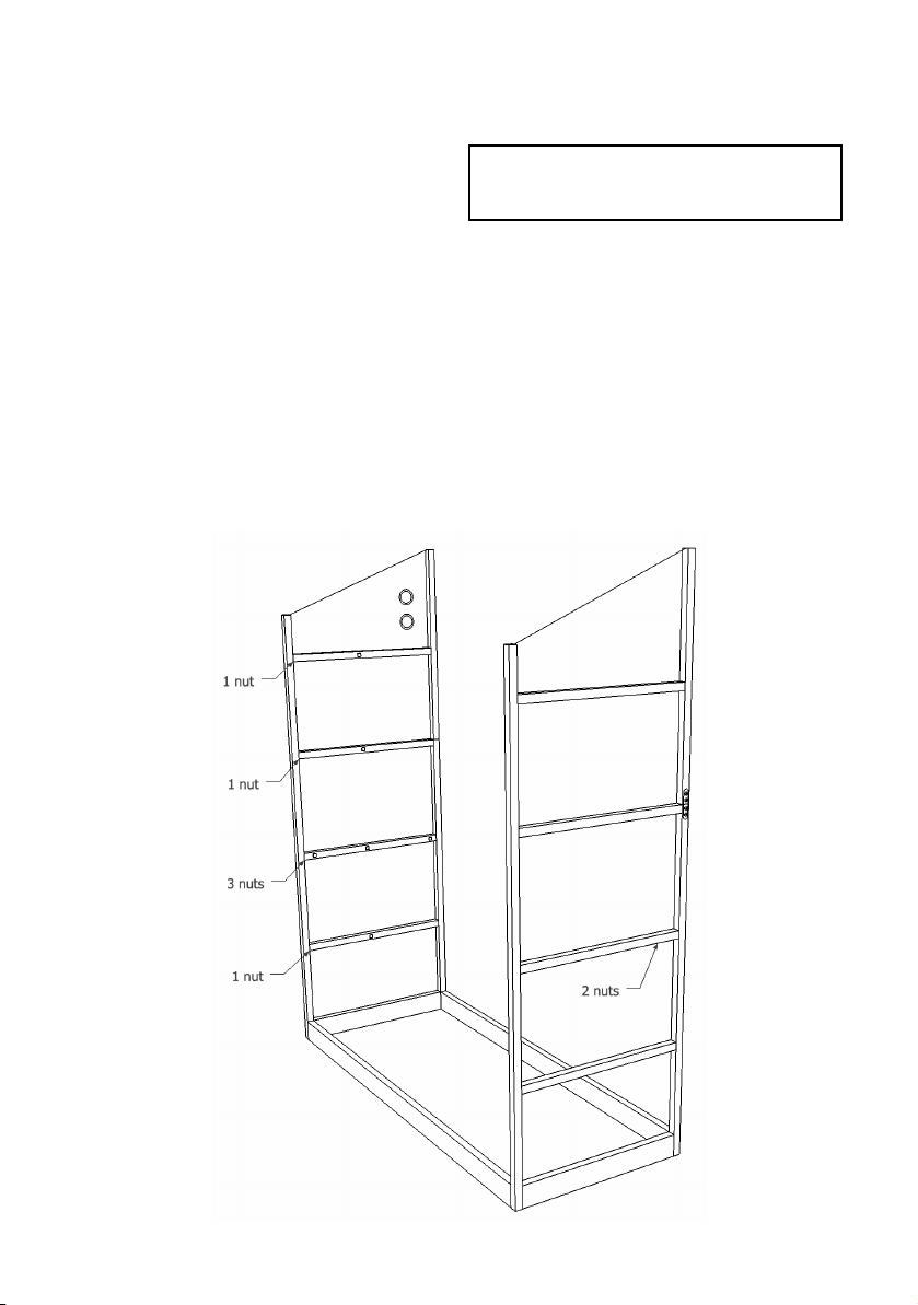
Step 5 - Insert square nuts to side cross bars
Parts
8 x side cross bar 45cm
8 x square nuts
Insert square nuts into the inside channel of each cross bar as per drawing below. Itʼs worth
fitting all the nuts now even if you donʼt have the irrigation kit yet - in case you want to fit it in the
future. The irrigation pipe will run up the le side of the greenhouse.
Note the extra nuts on the second bar up, for the shelf support brackets. Both le and right sides.
Step 6 - Insert the side panels and side cross bars
Parts:
8 x clear side panel
8 x side cross bar 45cm
2 x top clear side panel
Note the sequence of cross bars, with the
number of nuts in the drawing below.
Peel the protective plastic off both sides of
the side panels, remembering which side has
the white film; it should face outside as it is
UV treated.
Slot two panels into the frame, one on each
side.
Slide the bars, closed face outwards, down
over the clear side panels. Tighten the
screws.
Finish inserting all the side panels and cross
bars in the same way.
The top le panel has two holes, for
greenhouses with automated watering.
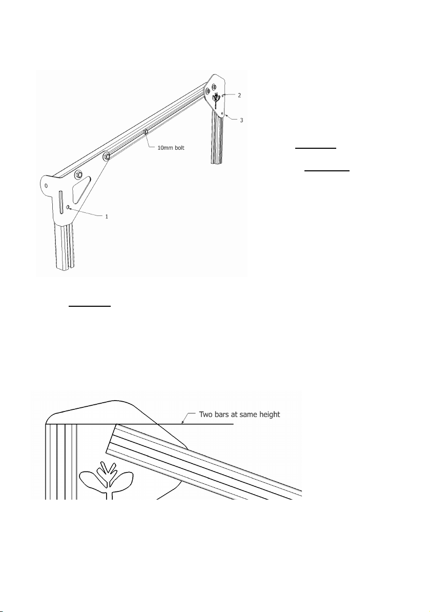
Step 7 - Fit the right side panel top assembly
Parts:
1 x Right side panel top assembly
3 x M5 * 8mm button head bolt
3 x M5 square nut
1 x M5 * 10mm button head bolt
Insert the 8mm bolts into the
assembly in positions marked 1,2,3,
and add the square nuts on the
inside, loosely.
Slide the assembly down over the
side panel, inserting the square
nuts into the outer channels on the
uprights.
Screw the 10mm bolt into the square nut which is already in the outside channel of the assembly
and tighten by hand. This will form part of the storm lock (see end of guide)
The front end goes down as far as it will go, and the rear end is flush with the top of the rear
upright (see drawing below).
Tighten the bolts.
Step 8 - Fit the le side panel top assembly
Repeat for the le hand side.
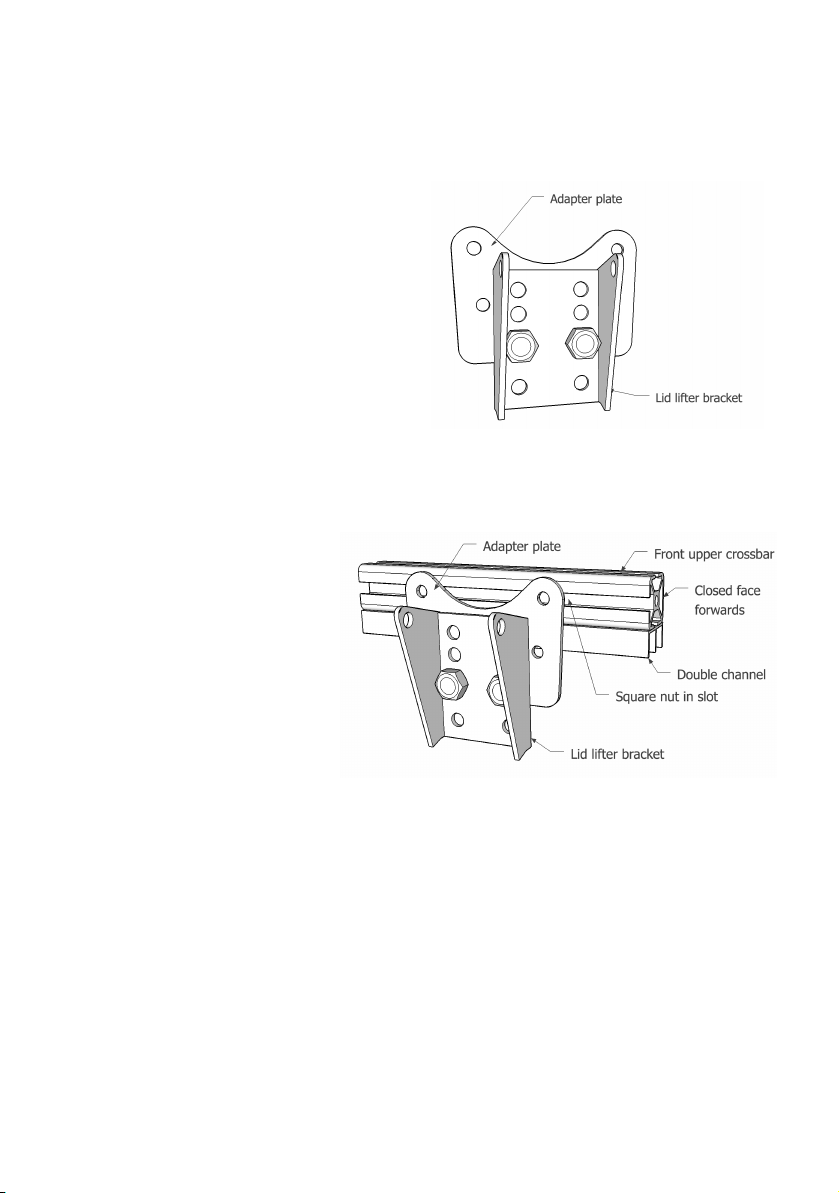
Step 9 - Fix lid lier bracket to adapter plate
OPTIONAL - if you have an automatic lid opener
The lid lier bracket is in the lid opener box. (see drawing below for named parts)
Parts:
1 x lid lier bracket
1 x adapter plate
2 x M5 x 8mm button head
2 x M5 nut
Bolt the lier bracket to the adapter plate as
shown, with the nuts on the inside of the
bracket.
Step 10a - Fix bracket to front bar : slot method
Parts:
1 x front upper bar 121cm
1 x bracket assembly from above
2 x M5 x 8mm button head
2 x M5 square nut
Slide two square nuts into the
rear channel of the bar (the side
opposite the closed face). Bolt
the bracket assembly to the front
bar, in the exact centre of the bar.
Step 10b - Through-hole method
If your greenhouse has a front crossbar with no slot, it will have holes drilled in the relevant
places.
Parts:
1 x front upper bar 121cm
1 x bracket assembly from step 9
2 x M5 x 30mm button head
2 x M5 nut
2 x M5 washer
Bolt the bracket to the front bar, through the
two holes using the 30mm bolts, washers
and nuts.

Step 11 - Add the lid prop bolt
This is the pivot bolt for the lid prop.
Note: If your crossbar does not have a slot, you will be provided with longer bolts (M5 x 30)
which go all the way through the bar from the front.
Parts:
1 x M5 x 16mm bolt
1 x M5 nut
1. Put the M5 nut loosely onto the 16mm bolt.
2. Slide the bolt head into the rear channel (same
channel as the lid lier bracket) on the right hand side
(with the lid lier bracket facing away from you)
3. Slide the bolt to 530mm from the right hand side.
4. Holding the thread of the bolt, tighten the nut to lock
the bolt in place.
The lid prop itself will be fitted later.

Step 12 - Insert the front crossbar
Parts
1 x M5 x 30mm bolt
1 x M5 x 40mm bolt
2 x M5 nut
2 x M5 washer
Bolt the front upper bar to the rear of the
brackets on the front of the greenhouse.
The 40mm bolt goes on the right hand side
to act as a support for the lid prop which
you will add later.
Tighten by hand (youʼll remove one bolt
later to li the crossbar to fit the doors)

Step 13 - Understand how the shelves fit
Refer to the drawing below to see which shelves are bolted to the frame, and which shelves
simply slot in. The bolted shelf supports give more strength to the frame.
A short section of 4mm tube pressed into the channel prevents the front shelf from sliding
forwards. When the mesh shelves are in place, the other shelf supports will not slide out.

Step 14 - Fit the shelf brackets to the frame
Parts
4 x M5 x 8mm cap head bolt
4 x shelf angle bracket
Screw the shelf brackets loosely onto the
end panel cross-bars, using the 8mm cap
head bolts into the square nuts already in
the channels.
Where the end panel has three nuts, leave
the middle one unused.
Step 15 - Fit the shelf supports
The shelf with the double holes half way along is fitted to the rear of the greenhouse.
The shelf without the holes is fitted to the front.
Parts
4 x M5 x 8mm cap head bolt
4 x M5 nut
1 x rear shelf support, 121cm
1 x front shelf support, 121cm
Fix the shelf support loosely to the bottom
of the bracket, using an 8mm bolt and a nut
underneath.
Push the rear shelf as far back as it will go,
without obstructing the channel on the
inside of the rear upright; this slot is where
the rear panels will fit.
Tighten all the bolts with the 4mm allen key.
Top tip: Once you have the bolted shelf supports in place, use a long strip of masking tape (or
similar) across the back of the greenhouse to hold the sides vertical.
Without the tape there is a tendency for the sides to splay out, and the slotted shelf supports
and rear panels may fall out. When the lid is screwed on later, you can remove the tape.

Step 16 - Slot in the rest of the shelf supports
The other shelf supports are slid into the slots on the cross bars, with the 4mm tubes pushed into
the slots in front of the front bars as per the drawing in step 13.
Step 17 - Fix the mesh panels
Once the shelf supports are in place, fix the mesh shelves to the shelf supports using cable ties.
The front top shelf support needs to be mounted further back to allow the lid lier piston to
swing, as per the drawing. Leave a 50mm gap between the le and right mesh panels for the
lier piston.

Step 18 - Install lower rear panels
Parts
2 x lower rear panel
1 x PVC H-trim 54cm
2 x cable tie
●Drop the lower rear panels (the smaller ones) into the
inner slots of the rear uprights. Ensure they go fully into
the lower base part - itʼs a tight fit.
●Slide the H-trim between the panels.
●Using the holes in the rear shelf as a guide, punch holes
through the rear panels and secure the panels to the shelf
support with cable ties.
Step 19 - Install upper rear panels
Parts
2 x upper rear panel
1 x PVC H-trim 84cm
1 x PVC H-trim 120cm
2 x long cable tie
●Put the long horizontal H-trim over the top of the lower
rear panels.
●Insert the two top panels.
●Slide the 84cm H-trim between the upper panels
Other manuals for S24
2
Table of contents
Other harvst Greenhouse Kit manuals

harvst
harvst Harvster User manual

harvst
harvst WaterMate User manual

harvst
harvst S14 User manual

harvst
harvst Terrace User manual

harvst
harvst S24 User manual

harvst
harvst Sprout S10 Mini User manual

harvst
harvst Terrace User manual

harvst
harvst Sprout S6 Mini User manual

harvst
harvst WaterMate User manual

harvst
harvst S14 User manual


Popular Greenhouse Kit manuals by other brands

GREENZONE
GREENZONE AA9DSN002XXXXX Assembly instruction

simpo
simpo 3-in-1 Garden System Assembly instruction

ENERAMA
ENERAMA Pyramid Garden Safety & Setup Instructions

Vitavia
Vitavia VM0048-VS 6200 Assembly instructions

Vitavia
Vitavia Hera 2 9000 Assembly instructions

Palram
Palram CANOPIA SANREMO 3x3 How to assemble


