harvst S24 User manual

Setup guide
Model S24
Greenhouse only, Solar, 3-season and 4-season versions
4-season model shown above
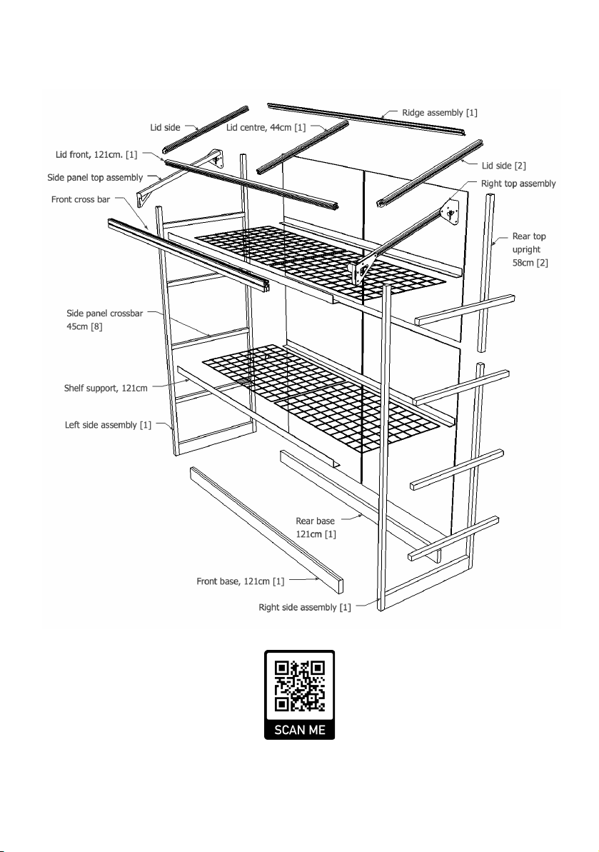
Exploded diagram
Visit www.harvst.co.uk/setup for more information, videos and photos

Thank you for buying a Harvst greenhouse.
If you have any questions while setting up, send us an email
(help@harvst.co.uk) or have a look at our forums at
https://grow.harvst.co.uk
There are also videos at
https://www.harvst.co.uk/setup
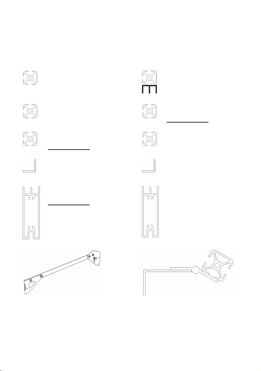
Parts list (aluminium pieces)
Weʼve fitted the front and rear uprights to the side base parts for you, to save
time and help you get started. Weʼve also pre-fitted screws into bars, where
required.
440mm x3
2 lid sides, with plastic corners
1 lid centre
1210mm x1
Front upper crossbar
(box profile as alternative)
450mm x8
Side panel crossbar
1285mm x2
Front upright
(fitted to assembly)
910mm x2
Rear upright
(fitted to assembly)
1250mm x1
Lid front
550mm x1
Lid prop
1210mm Shelf support
x4 GH / Solar models
x8 4-season model
450mm x2
Side base parts
(fitted to assembly)
1210mm x2
Front and rear base parts
Front with double channel up
Rear with single channel up
Side panel top assembly x2
One le and one right
Ridge assembly (with hinge) x1
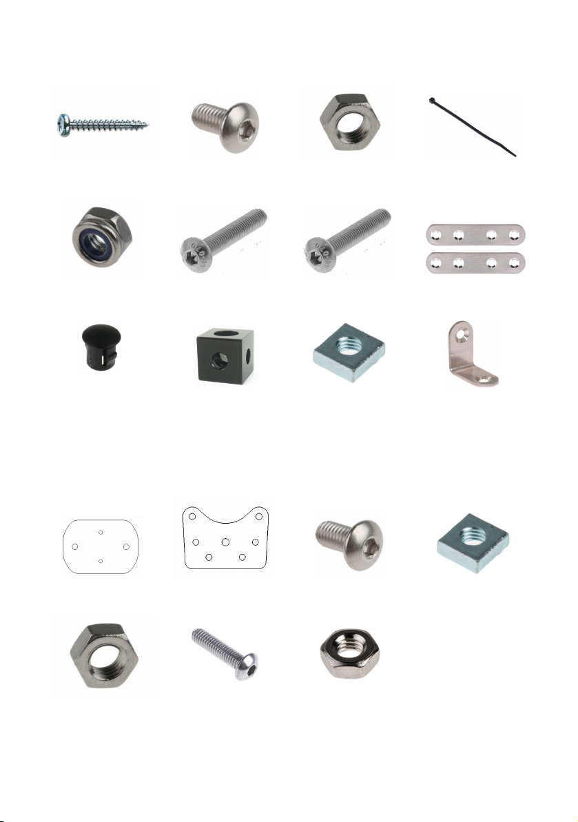
Fixings and small parts
4.5 x 30mm screws
M5 x 8mm
M5 nuts
20cm cable ties
M5 Nylock x1
M5 x 30mm x1
M5 x 40mm x1
Joining strap x2
Blanking plugs
Lid corner cube x2
M5 square nuts
Fixing brackets
Automatic lid lier fixings
(Solar, 3-season and 4-season models only)
Lier arm plate x1
Mounting plate x1
M5 x 8mm (or 25mm)
M5 square nuts
M5 nuts
M4 x 12mm
M4 nuts
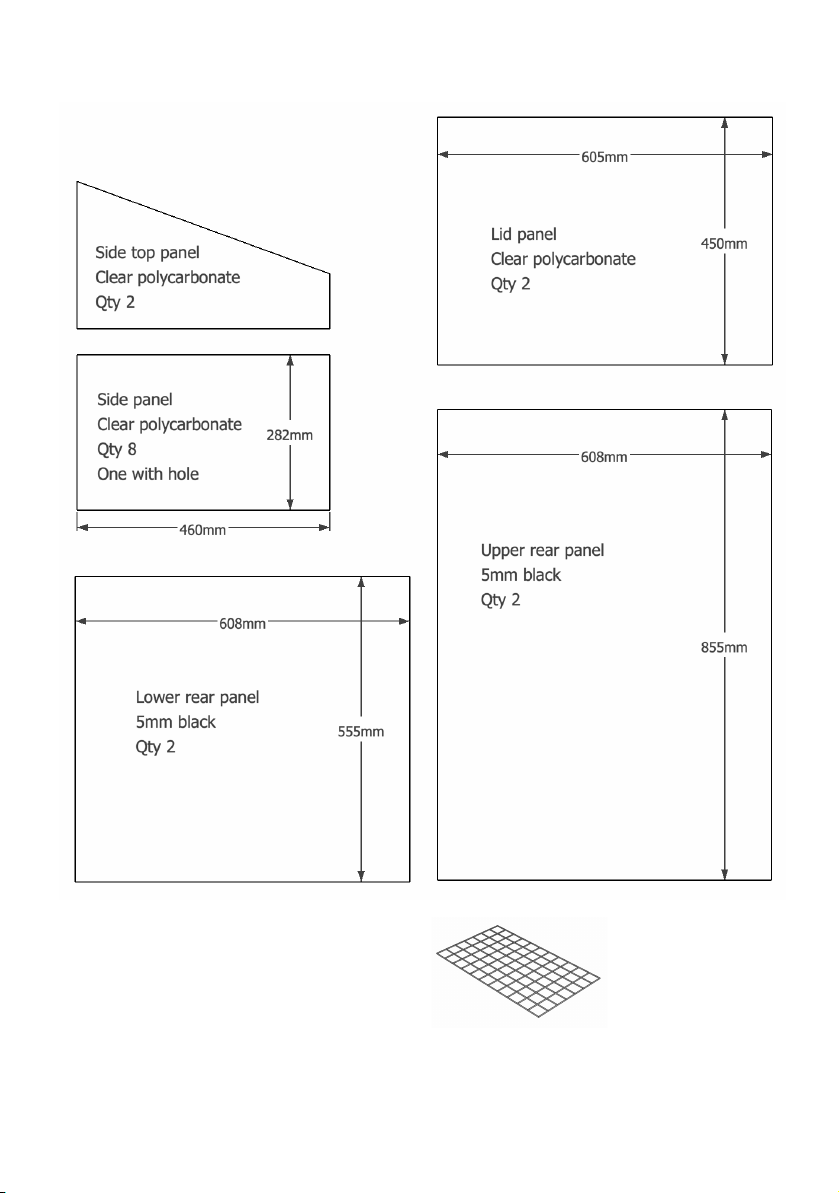
Panels
Tools provided
3mm allen key, 4mm allen key
8mm spanner
Pozidrive screwdriver
Tools required
Tape measure to check parts
Secateurs for cutting pipe
You will also have mesh shelves, the quantity
depending on which model you have bought.
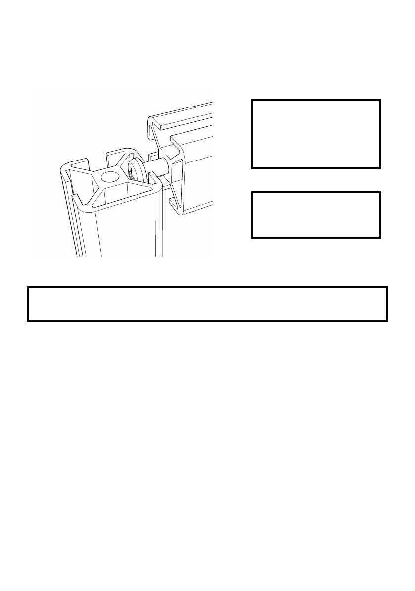
Slotting parts together
The greenhouse is based on parts that slot together using 30mm stainless steel screws, as shown
in the diagram below.
Ensure that your screwdriver is
fully engaged with the screw
head when you tighten, so that
you donʼt round off the head of
the screw.
Note the orientation of each
piece in the description;
specifically the closed face.
WARNING Every care has been taken during manufacture to avoid sharp edges or burrs,
however you should still take care when handling metal parts.
Step 1 - Seal the polycarbonate panels (optional)
Twin wall polycarbonate panels act like double glazing for your mini greenhouse, and to improve
the insulation characteristics, it is good to seal the ends of the channels using the provided foil
tape. It also helps prevent bugs from crawling into the plastic.
This step is optional - it can take some time but is recommended.
1. Peel back a couple of inches of the protective foil which covers both sides of the panels,
but donʼt take it all the way off yet.
2. Apply the tape to the end of the panel, covering the flutes.
3. Fold down the sides to seal the tape to the panels.
The white film is on the UV protected side which should face out when you place the panels into
the greenhouse.
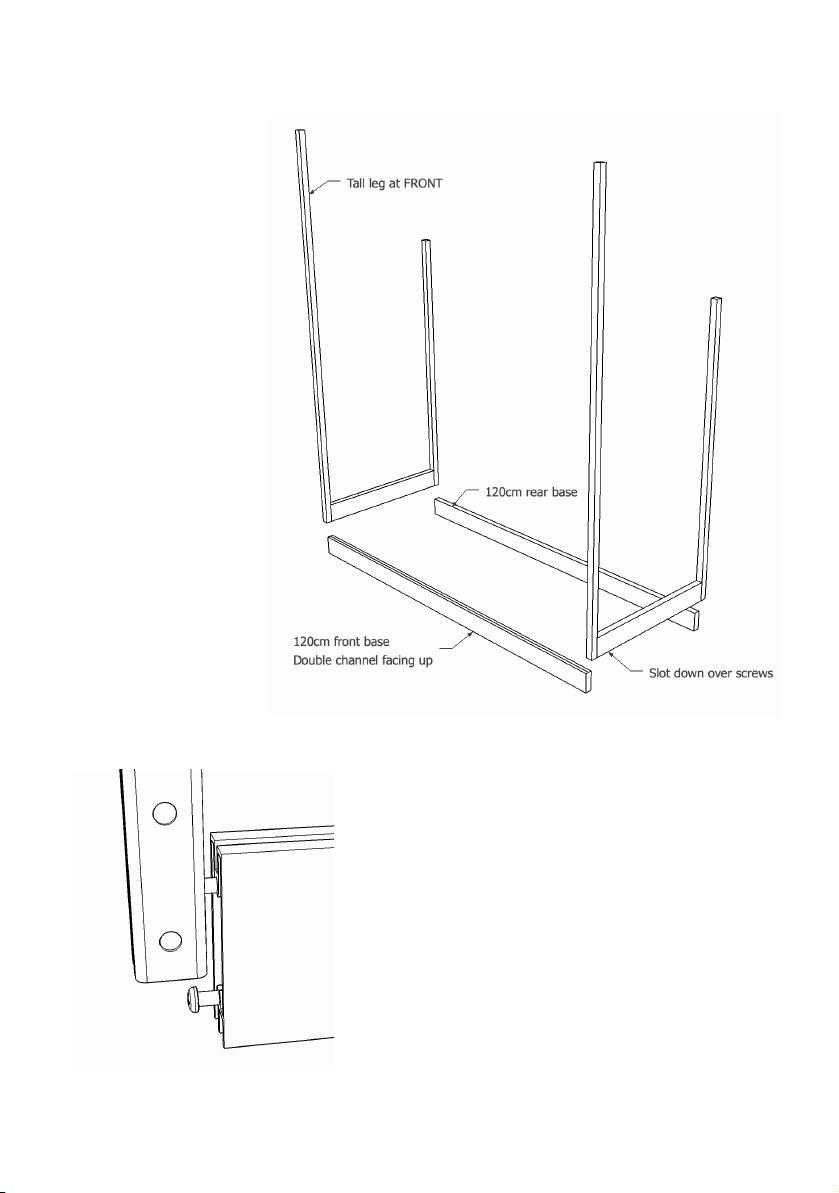
Step 2 - Assemble the base
Parts:
1 x le assembly
1 x right assembly
1 x front base 121cm
1 x rear base 121cm
This step is best done
on a flat surface where
you can easily access
the screws at the
bottom, such as a
table or workbench.
The le and right
assemblies are
interchangeable.
The rear base part has
the single channel
facing up, and the front
has the double
channel facing up.
Slot the le and right assemblies over the
screws on the front and rear base parts and
tighten the screws.
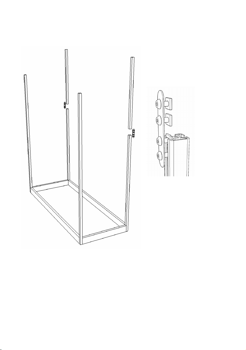
Step 3 - extend the rear uprights
Move the frame down onto the floor at this point.
Parts
2 x joining strap
8 x M5 x 8 button head
8 x M5 square nut
2 x top rear upright 56cm
Insert the bolts into the joining
straps, and put a square nut on the
back of each, loosely.
Slide the square nuts into the
outside channel of the rear
uprights.
Tighten the lower pair of bolts.
It can be a little fiddly to get the
square nuts to slide into the
channels. A small pair of pliers can
help keep them aligned.

Step 4 - Insert square nuts to side cross bars
Parts
8 x side cross bar 45cm
8 x square nuts
Insert square nuts into the inside channel of each cross bar as per drawing below. Itʼs worth
fitting all the nuts now even if you donʼt have the irrigation kit yet - in case you want to fit it in the
future. The irrigation pipe will run up the le side of the greenhouse.
Note the extra nuts on the second bar up, for the shelf support brackets. Both le and right sides.

Step 5 - Insert the side panels and side cross bars
The second side panel on the le has a hole with a grommet in it for an external hose or tank
connection, if you have a solar or 4-season model.
Parts:
8 x clear side panel
8 x side cross bar 45cm
Peel the protective plastic off both sides of two
side panels, remembering which side had the
white film.
The side with the white film should face
outside; it is the UV treated side.
Slot two panels into the frame, one on each
side.
Slide the bar, closed face outwards, down
over the clear side panel. Tighten the screws.
Repeat for the other side.
Finish inserting all the side panels and cross
bars in the same way.

Step 6 - Fit the side panel top assemblies
Parts:
1 x Right side panel top assembly
3 x M5 * 8mm button head bolt
3 x M5 square nut
Insert the bolts into the assembly,
and add the square nuts on the
inside, loosely.
Slide the assembly down over the
side panel, inserting the square
nuts into the outer channels on the
uprights.
The front end goes down as far as it will go, and the rear end is flush with the top of the rear
upright (see drawing below).
Tighten the bolts.
Repeat for the le hand side.

Step 7 - Fix lid lier bracket to adapter plate
OPTIONAL - if you have an automatic lid opener
The lid lier bracket is in the lid opener box. (see drawing below for named parts)
Parts:
1 x lid lier bracket
1 x adapter plate
2 x M5 x 8mm button head
2 x M5 nut
Bolt the lier bracket to the adapter plate as
shown, with the nuts on the inside of the
bracket.
Step 8a - Fix bracket to front bar : slot method
Parts:
1 x front upper bar 121cm
1 x bracket assembly from above
2 x M5 x 8mm button head
2 x M5 square nut
Slide two square nuts into the
rear channel of the bar (the side
opposite the closed face). Bolt
the bracket assembly to the front
bar, in the exact centre of the bar.
Step 8b - Through-hole method
If your greenhouse has a front crossbar with no slot, it will have holes drilled in the relevant
places.
Parts:
1 x front upper bar 121cm
1 x bracket assembly from step 9
2 x M5 x 30mm button head
2 x M5 nut
2 x M5 washer
Bolt the bracket to the front bar, through the
two holes using the 30mm bolts, washers
and nuts.
Step 9 - Add the lid prop bolt
This is the pivot bolt for the lid prop.
Parts:
1 x M5 x 40mm bolt
1 x M5 nut
Put the bolt through the hole just to the right of the middle of
the crossbar, from the front (the lid lier bracket is on the rear).
Secure it with the nut.
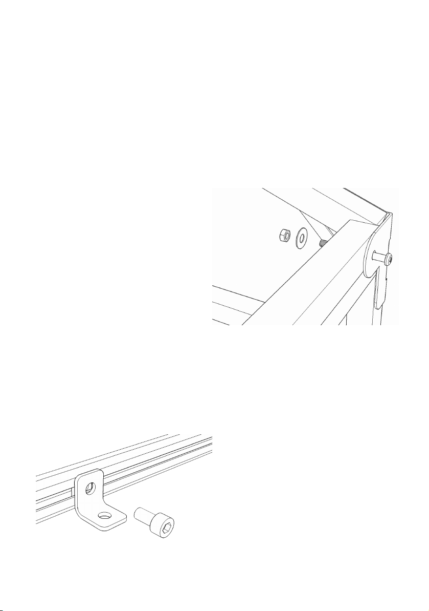
Step 10 - Insert the front crossbar
Parts
1 x M5 x 30mm bolt
1 x M5 x 40mm bolt
2 x M5 nut
2 x M5 washer
Bolt the front upper bar to the rear of the
brackets on the front of the greenhouse.
The 40mm bolt goes on the right hand side
to act as a support for the lid prop which
you will add later.
Tighten securely.
Step 11 - Fit the shelf brackets to the frame
Refer to the drawing in step 4 to see which nuts have brackets fitted. Only two of the shelf
support bars are bolted to the frame; the rest are slotted in.
Parts
4 x M5 x 8mm cap head bolt
4 x shelf angle bracket
Screw the brackets loosely onto the
cross-bars of the end panels, using the nuts
in the channels of the cross bars.

Step 12 - Fit the bolted shelf support bars
Two of the shelf support bars are bolted to the frame to hold the sides together.
Parts
4 x M5 x 8mm cap head bolt
4 x M5 nut
2 x angle aluminium, 121cm
Fix the shelf loosely to the bottom of the
bracket, using another M5x8mm bolt and a
nut underneath.
Push the rear shelf as far back as it will go,
without obstructing the channel on the
inside of the rear upright; this slot is where
the rear panels will fit.
Tighten all the bolts with the 4mm allen key.
Step 12b - Slot in the rest of the shelf supports
The other shelf supports are slid into the slots on the
cross bars.
The top shelf support is mounted upside down
and further back, to allow the lid lier piston to
swing clearly.
Leave a 40mm gap between the le and right
mesh panels for the lier piston.
Once the shelf supports are in place, fix the mesh
shelves to the supports using cable ties.

Step 13 - Install irrigation system (optional)
Self watering is provided either by sprayers or drippers, depending on what you want to grow
and how you would like to water it.
For sprayers, our
recommended setup is one
set of four sprayers under
each shelf, watering the
plants below.
The thin hose and sprayers
are fixed to the mesh shelf
with cable ties.
The top shelf can be
watered with drippers, or
you can add further 4mm
hoses into the riser pipe as
you see fit.
You can replace one or all
of the sprayers with
drippers, or any other
standard 4mm micro
irrigation part.
Water can be provided by
your choice of:
●Garden hose with
an external tap
timer
●Garden hose with
a Harvst smart
controller and
electric valves
●Harvst smart
controller with
water pump
Example setup. See website for irrigation details.
See our website for a range of videos which show you how to connect up various different
water sources to your greenhouse irrigation. www.harvst.co.uk/setup

Step 14 - Fit the grow lights - optional
The 4-Season greenhouses can be fitted with grow lights. Up to a maximum of six per control unit
output (see notes on control unit maximum capacity).
Per shelf:
2 x light bar
8 x cable tie
With the cables on the le, fix the lights to the underside of the
mesh shelves using cable ties through the small holes.
Extra light pairs
Extra splitters
For each pair of lights, connect a 3-way splitter to the lights,
leaving a spare socket to connect to the shelf below.
Connect the lights to the control unit later.
Step 15 - Fit the heater cable(s) - optional
Parts
Heater cable(s)
100mm cable ties
Fit one heater cable to the top socket on the le hand side of
the control unit. If you have a second heater cable, it goes in
the middle socket.
Weave the cable in and out of the shelf mesh, to provide a
heated platform on which you place your growing containers.
The cable will reach a maximum of 60 degrees C which will not
damage any of the greenhouse frame or plastic.

Step 16 - Install lower rear panels
Parts
2 x lower rear panel
1 x PVC H-trim 54cm
2 x long cable tie
Drop the lower rear panels (the smaller ones) into the inner slots of
the rear uprights. Ensure they go fully into the lower base part - itʼs
a tight fit.
Use a so hammer or block of wood to gently tap the rear panel
into the base part so that it is true and square.
Slide the H-trim between the panels.
Using the holes in the rear shelf as a guide, punch holes through
the rear panels and secure the panels to the shelf with the long
cable ties.
Step 17 - Install upper rear panels
Parts
2 x upper rear panel
1 x PVC H-trim 84cm
1 x PVC H-trim 120cm
2 x long cable tie
Put the long H-trim over the top of the lower rear panels.
Insert the two top panels.
If you have a control system to install, complete the next step
before inserting the shorter section of H-trim between the panels.

Step 18 - Fix controls to upper le rear panel
Parts
2 x M5 x 16mm bolt
2 x M5 washer
2 x M5 nut
Fit the control unit to the rear panel using the 2 holes at the top le
of the panel. Flip the mounting hole covers up on the control unit
to expose the mounting holes. Itʼs easiest to hold the bolts on the
allen key as you push them through the control unit.
Parts
2 x M4 x 16mm bolt
2 x M4 penny washer
2 x M4 nut
Optional : power supply (mains version) : Fit the power supply to
the rear panel using the two holes to the right of the control unit.
The long mains cable goes on the right.
Feed the power cable out through the slot in the rear panel.

Step 19 - Fit the doors
Parts
2 x polycarbonate door
With handles fitted
Remove one of the bolts that fix the front crossbar, so you can
pivot it up.
Slot the doors in, drop the crossbar back into place and secure it
with the bolt.
The le hand door goes in the rear (inside) channel and the right
hand door goes in the front (outside) channel.
Step 20 - Fit the lid prop
Parts
1 x lid prop, 55cm
1 x M5 nyloc nut
Note: The nyloc nut has a little plastic ring
inside to prevent it loosening.
Put the hole in the lid prop over the stud
formed by the bolt on the front crossbar.
Put on the nyloc nut, tightening it just so that
the plastic “bites” the thread. The prop
should be loose enough to move around.
The right hand end of the lid prop rests on the bolt which secures the front bar.
Other manuals for S24
2
Table of contents
Other harvst Greenhouse Kit manuals

harvst
harvst Sprout S6 Mini User manual

harvst
harvst S14 User manual

harvst
harvst WaterMate User manual

harvst
harvst S14 User manual

harvst
harvst WaterMate User manual

harvst
harvst Sprout S10 Mini User manual

harvst
harvst Sprout S6 Mini User manual

harvst
harvst S24 User manual

harvst
harvst Sprout S10 Mini User manual

harvst
harvst Terrace User manual


