harvst Sprout S6 Mini User manual

Setup guide
Model S6
Greenhouse only
V4 / From Feburary 2023
If you have a Smart Sprout please also use the smart setup guide whilst
assembling your S10

Thank you for buying a Harvst Sprout mini
greenhouse.
If you have any questions while setting up, send us an email
(help@harvst.co.uk) or check out our forums:
https://grow.harvst.co.uk
Important information
Sprout Mini Greenhouses are intended for outdoor use and should be
secured to a fence or wall with the provided fixings. Harvst accept no
liability for incorrectly used products.Exploded diagram

Tools provided
3mm allen key
8mm spanner
Pozidrive screwdriver
Tools required (not supplied)
Tape measure to identify parts
Secateurs for cutting pipe

Parts list (aluminium pieces)
Weʼve fitted the front and rear uprights to the base parts for you, to save time and
help you get started. Weʼve also pre-fitted screws into bars, where required.
450mm x2
Lid sides, with corner cubes
600mm x1
Front crossbar
450mm x4
Side panel crossbar
2 pre installed screws per
piece
Front assembly x1
728mm uprights
600mm base
Rear assembly x1
910mm uprights
600mm base
600mm x1
Lid front
Door handles x2
610mm
Shelf supports x2
4 season kits will have a
LED shelf support bars
450mm x2
Side base parts with screws
1250mm two part lid hinge
x1

Side panel top assembly x2
One le and one right
Top mesh panel x1
Fixings and small parts
M5 x 8mm x12
M5 x 10mm x10
M5 x 16mm x2
M5 x 30mm x2
M5 Nyloc x6
M5 square nut x23
4.5 x 30 countersunk
head screws x2
4.5 x 30 dome head
screw x2
Blanking plug x10
M5 washer x2
Fixing bracket x2
10cm cable ties x20
Lid top plate x1
Adapter plate x1
4mm tubes for
shelving
90mm x2
190 x2
Roll of foil tape

3mm allen key
Screwdriver
8mm spanner
O-ring x2
Panels
Black rear panel x1
Clear lid panel x1
Clear side panels x 8
Clear side top panel - le x1
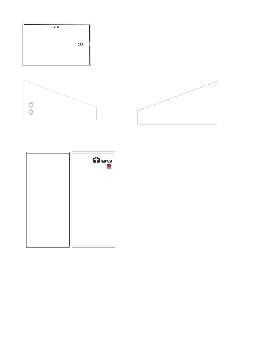
Note: Holes for piping
Clear side top panel - right x1
Door pair x1

Introduction - slotting parts together
The greenhouse is based on parts that slot together using stainless steel screws, as shown in the
diagram below. These are self tapping screws which require a little bit of force to get them fully
seated.
Ensure that your screwdriver is
fully engaged with the screw
head when you tighten, so that
you donʼt round off the head of
the screw.
Note the orientation of each
piece in the description;
specifically the closed face.
Every care has been taken during manufacture to avoid sharp edges or burrs, however you
should still take care when handling metal parts.
WARNING DO NOT USE POWER TOOLS TO SCREW IN THE SCREWS. YOU MIGHT SNAP OFF
THE HEAD, WHICH IS NOT COVERED BY WARRANTY.
Step 1 - Seal the polycarbonate panels (optional)
Twin wall polycarbonate panels act like double glazing for your mini greenhouse, and to improve
the insulation characteristics, it is good to seal the ends of the channels using the provided foil
tape. It also helps prevent bugs from crawling into the plastic.
1. Peel back a couple of inches of the protective foil which covers both sides of the panels,
but donʼt take it all the way off yet.
2. Apply the tape to the end of the panel, covering the flutes.
3. Fold down the sides to seal the tape to the panels.
The white film is on the UV protected side which should face out when you place the panels
into the greenhouse.
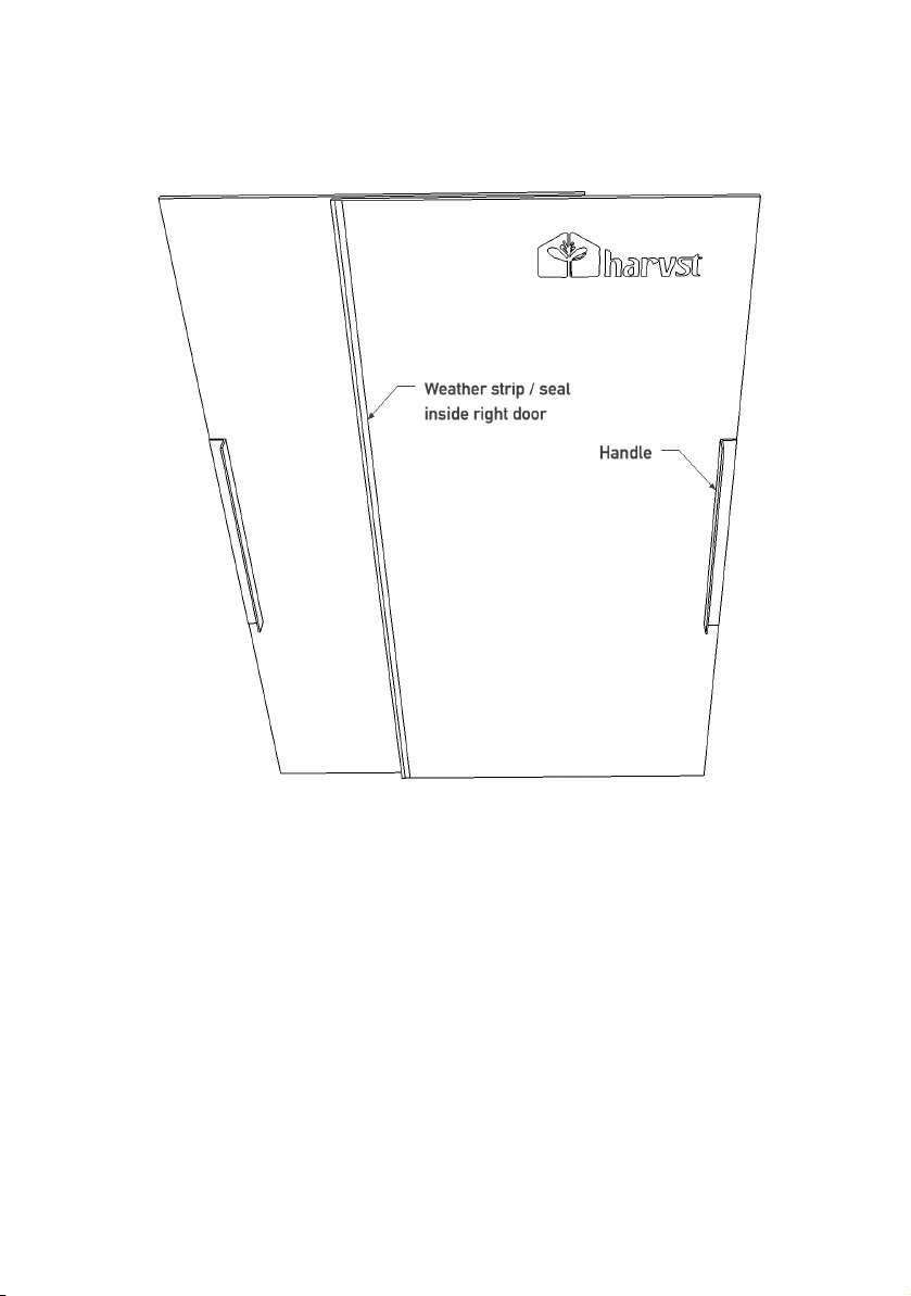
Step 2 - Fit the door handles
Do this step first to allow the adhesive tape to cure before fitting the doors at the end.
Parts
2 x door handle
1 x door pair
Fix the door handles to the doors as shown in the drawing
above, using the tape fixed to the handles.
Make sure you have peeled the protective film off the doors
first, that the surfaces are clean, dry and free from grease, and
that the UV treated side of the door panels (white film) faces
out.
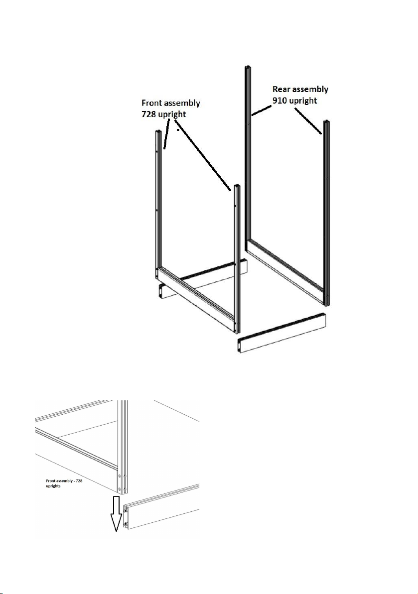
Step 3 - Assemble the base
Parts:
1 x front assembly
1 x rear assembly
2 x side base 45cm
This step is best done
on a flat surface where
you can easily access
the screws at the
bottom, such as a
table or workbench.
The closed faces on the
assembly uprights face
outside the
greenhouse.
Place the two side
bases with the single
channel facing up.
Slot the front assembly over the screws on the
side basees and tighten the screws.
Do the same for the rear assembly.
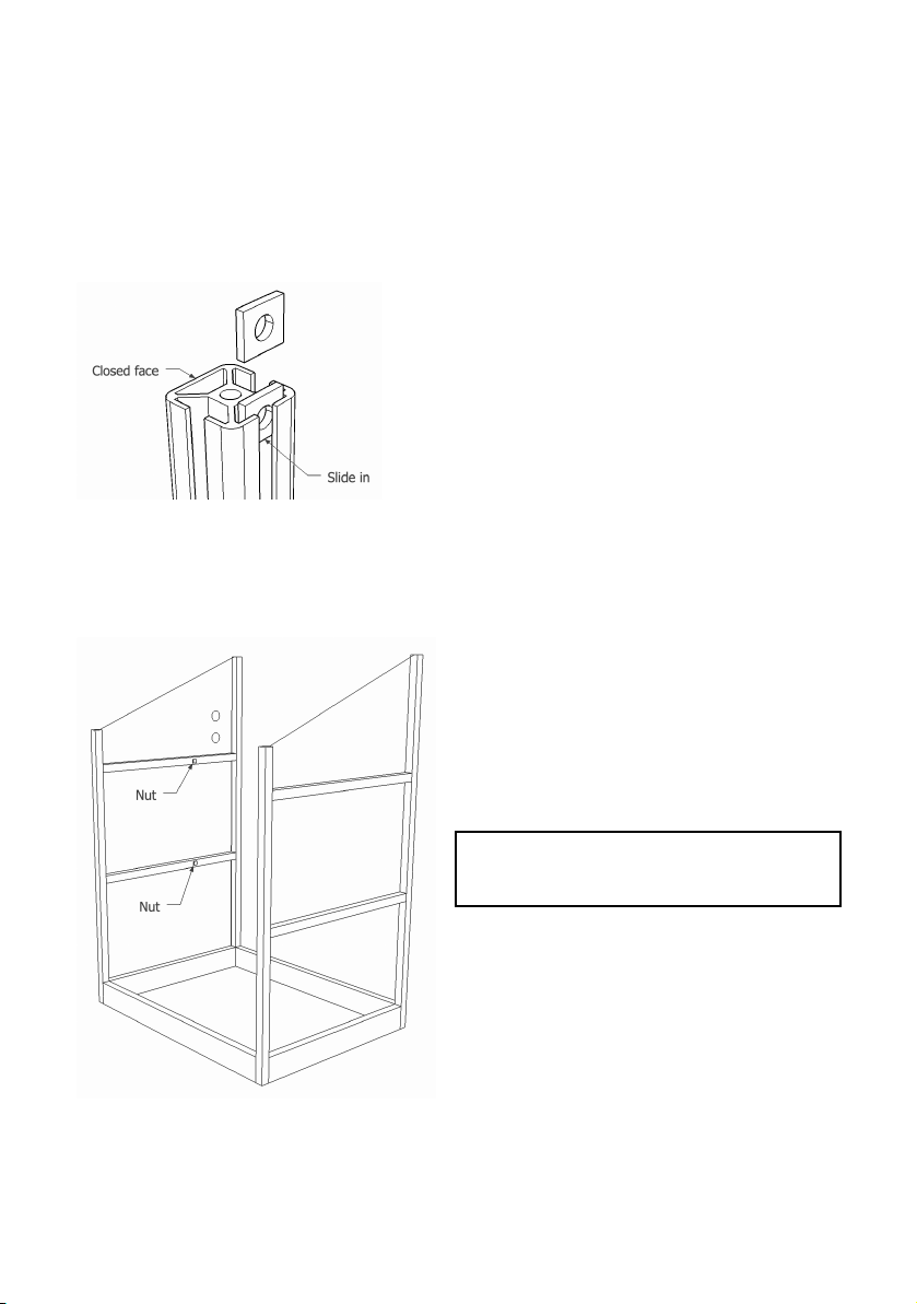
Step 4 - Insert square nuts into cross bars
Parts
2 x side cross bar 45cm
2 x M5 square nut
Insert one square nut into the inside channel of each
cross bar that will go on the le side of the
greenhouse.
The inside channel is the one opposite the closed
face.
These nuts are for irrigation parts which you may or
may not add in the future.
Step 5 - Insert the side panels and side cross bars
Parts:
4 x clear side panel
4 x side cross bar 45cm, two with nuts
Peel the protective plastic off both sides of two
side panels, remembering which side had the
white film.
The side with the white film should face
outside; it is the UV treated side.
Insert the bottom two clear side panels.
Slide a bar with square nut in the inside
channel over the le panel.
Slide a bar without a nut over the right panel.
Tighten the screws.
Finish inserting all the side panels and cross
bars in the same way.
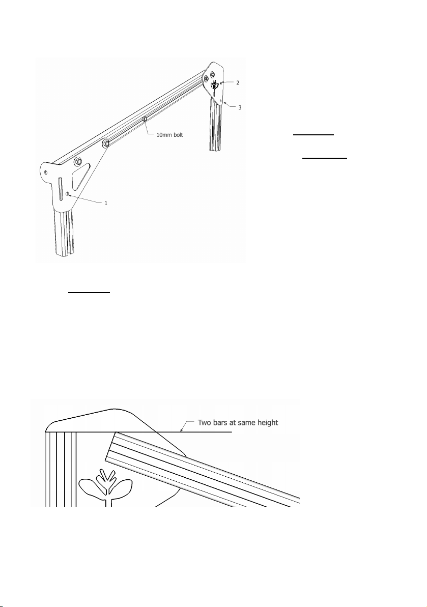
Step 6 - Fit the right side top assembly
Parts:
1 x Right side top assembly
3 x M5 * 8mm button head bolt
3 x M5 square nut
1 x M5 * 10mm button head bolt
Insert the 8mm bolts into the
assembly in positions marked 1,2,3,
and add the square nuts on the
inside, loosely.
Slide the assembly down over the
side panel, inserting the square
nuts into the outer channels on the
uprights.
Screw the 10mm bolt into the lower square nut which is already in the outside channel of the
assembly and tighten by hand. This will form part of the storm lock (see end of guide for more
info.) Ensure the second square nut in the channel is further up towards the rear of the
extrusion.
The front end goes down as far as it will go, and the rear end is flush with the top of the rear
upright (see drawing).
Tighten the bolts.

Step 7 - Fit the le side top assembly
Parts:
1 x Le side top assembly
3 x M5 * 8mm button head bolt
3 x M5 square nut
Repeat step 6 for the le hand side top assembly
Step 8 - Fix lid lier bracket to adapter plate
This step is only relevant if you have purchased an automatic lid opener.
Parts in Lier Box :
1 x Piston Clip (end of box)
1 x Piston
1 x Arm
1 x Lier Bracket
The lid lier bracket is in the lid opener box.
Parts:
1 x lid lier bracket
1 x adapter plate
2 x M5 x 8mm button head
2 x M5 nyloc nut
Bolt the lier bracket to the adapter plate as
shown in the diagram to the right, with the
nyloc nuts on the inside of the bracket.
Step 9 - Fix bracket to front crossbar
Parts:
1 x front cross bar 60cm
1 x bracket assembly from step 8
2 x M5 x 8mm button head
2 x M5 square nuts
Slide two square nuts into the rear channel (the side opposite the closed face). Bolt the bracket
assembly in the exact centre of the bar.
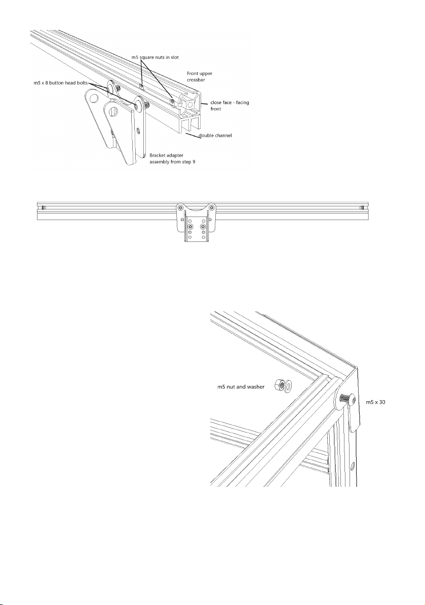
Step 10 - Insert the front crossbar
Parts
2 x M5 x 30mm bolt
2 x M5 nyloc nut
2 x M5 washer
Use the M5 x 30 bolts to secure the front
crossbar to the rear of the side assembly
corner brackets.
Fix them in place with a washer and nyloc
nut on the rear.
Tighten so that the top door bar is secure.

Step 11 - Understand how the shelves fit
Refer to the drawing below to see the recommended position of the shelves.
Note: If you have a 4 seasons model please refer to your smart control guide for layout of
additional shelves
Parts:
2 x 90mm length 4mm pipe
2 x 190mm length 4mm pipe
A short section of 4mm tube pressed into the channel prevents the front shelf from sliding
forwards.
Use 190mm in front of the top shelf and 90mm length in your other shelf if applicable.

Step 12 - Fit the shelves
Parts:
Mesh shelves
2 x 610mm shelf support per shelf
4 x 10cm cable tie per shelf
Slide the square nuts for the 13mm water
pipe to the middle of the crossbars on the le
hand side of the frame, before you insert the
shelf supports.
Slot the shelf supports into the slots on the inside of the
side panel cross bars, inserting them at a diagonal and
then straightening up.
Place the mesh shelves onto the shelf supports and secure
with cable ties, one in each corner.
NOTE: The mesh shelf with a
slot cut out goes in the top
level to allow the lid lier
piston to operate. The front
shelf support goes in upside
down.
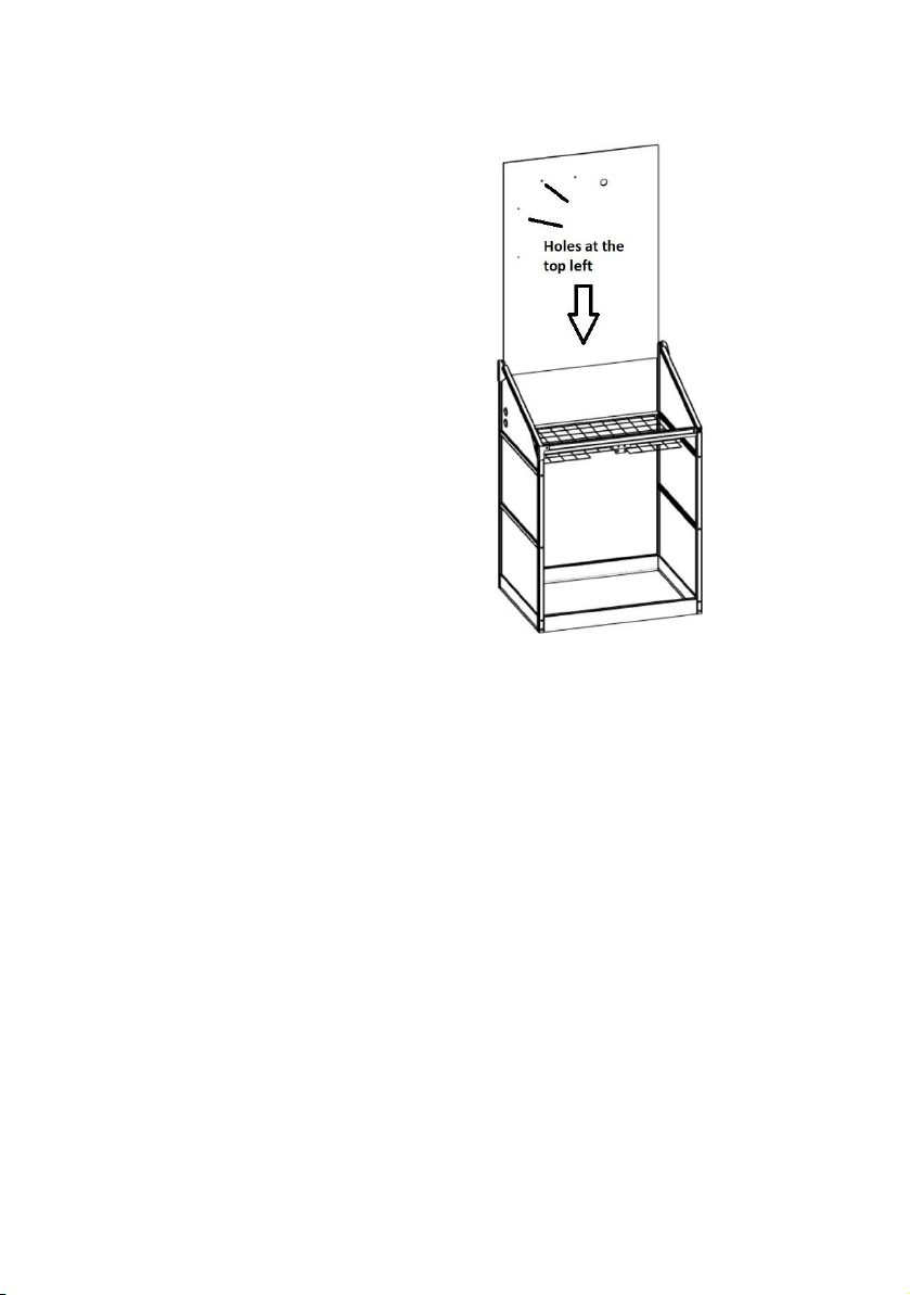
Step 13 - Install rear panel
Parts
1 x black rear panel
Drop the rear panel into the inner slots of the
rear uprights.
Ensure it goes fully into the lower base part -
itʼs a tight fit.
Note: Ensure the panel holes are in the top
le orientation when installing the panel
This step can be made easier by squeezing
the edges of the panels that will be in the
slots of the frame so that they are slightly
deformed.
Step 14 - Assemble the lid
Parts
1 x lid ridge
1 x lid bar rear
2 x lid side bars with corner caps
6 x M5 square nuts
2 x 30mm countersunk head screws
1 x 60cm lid front bar
1 x clear lid panel
a) Lay out the lid front bar onto a flat surface with the closed face facing downwards.
Attach the lid side bars with the corner piece to the lid front. The le and right lid side
bars are identified by L and R on their protective packaging.
Line up the corner piece with the open end of the lid front bar and use the countersunk
30mm screw to gently pull the corner piece into the end of the front bar

Repeat above steps for the le lid side
b) Peel back the film from the lid panel faces. The white side is outside facing. Slot the
clear lid panel into the internal area of the lid paying attention to the notches in the lid
panel corners as circled in the diagram below.

Insert 3 square nuts into the outside slot of the le/ right side bars.
c) Slide the ridge bar slotted face over the screws of the sidebar. Once positioned, tighten
the 2 screws in the side bars to fix the lid ridge in place.
Step 15 - Add lid props to lid
This is easiest done on a flat table or worktop.
Parts
2 x lid props
2 x m5 x 10 button head bolts

Note orientation of the lid prop
Secure the lid prop bracket. Measure 100mm from the rear of the lid sidebar to the centre of the
bolt and secure the bolt through the lid prop hole and into the square nut in the slot. Tighten
well.
Repeat for the other side, see diagram below.
Step 16 - Assemble lid lier
Parts
1 x lid lier piston
Insert the black lid lier piston into the lid lier, using the
instructions as supplied in the lier box.
Step 17 - Fit the lid lier to the lid
Parts:
2 x M5 x 16mm bolt
2 x M5 nyloc nut
1 x lid top plate
1 x lid lier
Locate the lid top plate in the orientation of the
diagram below on the exterior/ top of the lid. The
bottom lip of the plate below the harvst logo slots into
the gap between lid panel and the front lid bar for
support. The two holes on the lid top plate should
align with the holes on the lid panel.
Other manuals for Sprout S6 Mini
2
Table of contents
Other harvst Greenhouse Kit manuals

harvst
harvst S24 User manual

harvst
harvst S14 User manual

harvst
harvst Sprout S6 Mini User manual

harvst
harvst Terrace User manual

harvst
harvst Harvster User manual

harvst
harvst Terrace User manual

harvst
harvst Yard User manual

harvst
harvst Sprout S10 Mini User manual

harvst
harvst S14 User manual

harvst
harvst S14 User manual


