harvst S14 User manual

Setup guide
Model S14
Greenhouse only
V4 / From January 2023
If you have a Smart Sprout please also use the smart setup guide whilst
assembling your S14

Thank you for buying a Harvst Sprout mini
greenhouse.
If you have any questions while setting up, send us an email
(help@harvst.co.uk) or check out our forums:
https://grow.harvst.co.uk
Important information
Sprout Mini Greenhouses are intended for outdoor use and should be
secured to a fence or wall with the provided fixings. Harvst accept no
liability for incorrectly used products.
Parts / assembly diagram

Tools provided
3mm allen key, 4mm allen key
8mm spanner
Pozidrive screwdriver
Tools required (not supplied)
Tape measure to identify parts
Secateurs for cutting pipe

Parts list (aluminium pieces)
Weʼve fitted the front and rear uprights to the side base parts for you, to save
time and help you get started. Weʼve also pre-fitted screws into bars, where
required.
450mm x3
2 lid sides, with corner cubes
1 lid centre
1210mm x1
Front crossbar
Double channel trim attached
450mm x4
Side panel crossbar
2 pre installed screws per piece
1210mm x1
Lid front bar
1 - hole through open faces
Side assemblies x2
Front uprights - 728mm
Rear uprights - 910mm
Base extrusion - 450mm
Shelf supports x2
1 pair drilled - 1210mm
1210mm x2
Front and rear base parts
With pre installed screws
Front with double channel up
Rear with single channel up
1250mm two part lid hinge x1
Side panel top assembly x2
One le and one right

Lid prop x2
Door handles x 2
H trim
830mm x1
14” x 22” mesh
panels x2
Fixings and small parts
Button head
M5 x 8mm x14
Button head
M5 x 10mm x12
Cap head
M5 x 8mm x8
M5 x 30mm x2
M5 square nut x24
M5 Nyloc x10
Shelf bracket x4
Fixing bracket x2
4.5 x 30 countersunk
head screws x2
4.5 x 30 dome head
screw x2
4mm tube for fixing
shelves
160mm x 2
M5 washer x2

10cm cable tie x12
20cm cable tie x10
Blanking plug x11
Lier arm plate x1
Mounting plate x1
Hole punch
O-ring x2
Roll of foil tape
Panels

Above - note the orientation of the lid panels relative to the notches in the bottom le/right
respectively.
Clear side top panel - le x1
Note: Holes for piping
Clear side top panel - right x1
Clear side panels x4

Slotting parts together
The greenhouse is based on parts that slot together using 30mm stainless steel screws, as shown
in the diagram below. These are self tapping screws which require a little bit of force to get them
fully seated.
Ensure that your screwdriver is
fully engaged with the screw
head when you tighten, so that
you donʼt round off the head of
the screw.
Note the orientation of each
piece in the description;
specifically the closed face.
WARNING Every care has been taken during manufacture to avoid sharp edges or burrs,
however you should still take care when handling metal parts.
WARNING DO NOT USE POWER TOOLS TO SCREW IN THE SCREWS. YOU MIGHT SNAP OFF
THE HEAD, WHICH IS NOT COVERED BY WARRANTY.
Step 1 - Seal the polycarbonate panels (optional)
This step is optional, but is recommended.
Twin wall polycarbonate panels act like double glazing for your mini greenhouse. To improve the
insulation characteristics, itʼs good to seal the ends of the channels using the foil tape provided.
It also helps prevent bugs from crawling into the plastic.
1. Peel back a couple of inches of the protective foil which covers both sides of the panels,
but donʼt take it all the way off yet.
2. Apply the tape to the end of the panel, covering the flutes / open ends.
3. Fold down the sides to seal the tape to the panels.

The white film is on the UV protected side which should face out when you place the panels
into the greenhouse.
Step 2 - Attach the door handles
Do this step first to allow the adhesive tape to cure while you assemble the rest of the
greenhouse. Youʼll fit the doors at the end.
Parts
2 x door handle
2 x polycarbonate door
Fix the door handles to the doors as shown in the drawing
above, using the tape fixed to the handles.
Make sure you have peeled the protective film off the doors
first, the surfaces are clean, dry and free from grease, and that
the UV treated side of the door panels (white film) faces out.
There is a sticker on the right door.
The le, inner door has a weather strip fitted to the front to
reduce draughts in the greenhouse.
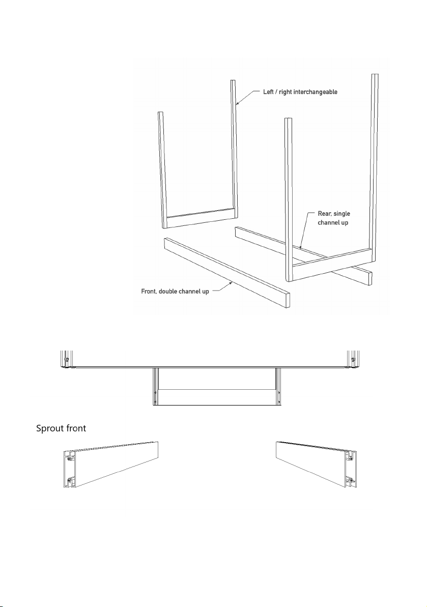
Step 3 - Assemble the base
Parts:
2 x side assemblies
1 x front base 121cm
1 x rear base 121cm
This step is best done
on a flat surface where
you can easily access
the screws at the
bottom, such as a
table or workbench.
The le and right
assemblies are
interchangeable.
NOTE:
The rear base part
has the single
channel facing up,
and the front has the
double channel
facing up.

Slot the le and right assemblies over the screws on the front and rear base parts and tighten the
screws using the screwdriver provided.
Step 4 - Insert square nuts to side cross bars
Parts
4 x side panel cross bar 45cm
6 x square nut
See the drawing in step 6 and insert square nuts into
the cross bars.
Two will be for the shelves, and the third will be for
supporting the irrigation pipe (itʼs worth fitting the
nuts now even if you donʼt have the irrigation kit yet).
The inside channel is the one opposite the closed
face.
Insert square nuts into the inside channel of each
cross bar according to the following quantities per
cross bar:
- 1 lengths with 1 square nut
- 1 length with 3 square nuts
- 1 length with 2 square nuts
You can refer to the diagram in step 5 for reference.

Step 5 - Insert the side panels and side cross bars
Parts:
4 x clear side panel
4 x side cross bar 45cm
2 x clear side top panel
Note the sequence of cross bars,
with the number of nuts in the
diagram to the le
Peel the protective plastic off both
sides of two side panels, remembering
which side had the white film.
The side with the white film should
face outside; it is the UV treated
side.
Slot the panels into the frame, then
slide the bars, closed face outwards,
down over the clear side panels.
Tighten the screws.
Finish inserting all the side panels and
cross bars in the same way.
Step 6 - Fit right side top assembly
Parts:
1 x Right side top assembly
3 x M5 * 8mm button head bolt
3 x M5 square nut
1 x M5 * 10mm button head bolt
Insert the 8mm bolts into the
assembly in positions marked 1,2,3,
and add the square nuts on the
inside, loosely.
Slide the assembly down over the
side panel, inserting the square
nuts into the outer channels on the
uprights.

Screw the 10mm bolt into the square nut which is already in the outside channel of the assembly
and tighten by hand. This will form part of the storm lock (see end of guide)
Ensure the second square nut in the channel is further up towards the rear of the extrusion.
The front end goes down as far as it will go, and the rear end is flush with the top of the rear
upright (see drawing below).
Tighten the bolts.
Step 7 - Fit le side top assembly
Parts:
1 x Le side top assembly
3 x M5 * 8mm button head bolt
3 x M5 square nut
1 x M5 * 10mm button head bolt
Repeat step 6 for the le hand side.

Step 8 - Fix lid lier bracket to adapter plate
This step is only relevant if you have purchased an automatic lid opener.
Parts in Lier Box :
1 x Piston Clip (end of box)
1 x Piston
1 x Arm
1 x Lier Bracket
The lid lier bracket is in the lid opener box.
Parts:
1 x lid lier bracket
1 x adapter plate
2 x M5 x 8mm button head
2 x M5 nyloc nut
Bolt the lier bracket to the adapter plate as
shown in the diagram to the right, with the
nyloc nuts on the inside of the bracket.
Step 9 - Fix bracket to front crossbar
Parts:
1 x front upper bar 121cm
1 x bracket assembly from above
2 x M5 x 8mm button head
2 x M5 square nut
Slide two square nuts into the
rear channel (the side opposite
the closed face). Bolt the bracket
assembly in the exact centre of
the bar.

Step 10 - Insert the front crossbar
Parts
2 x M5 x 30mm bolt
2 x M5 nyloc nut
2 x M5 washer
Use the M5 x 30 bolts to secure the front
crossbar to the rear of the side assembly
corner brackets.
Fix them in place with a washer and nyloc
nut on the rear.
Tighten so that the top door bar is secure.
Step 11 - Understanding shelf fitting
Study the drawing below to see how the shelves fit. The top shelves are bolted, and if you
additional shelves for a smart sprout the bottom shelf is slotted in

Step 12 - Assemble shelf supports
The shelf with the double holes half way along is fitted to the rear of the greenhouse.
The shelf without the holes is fitted to the front. This step can be easier with an additional pair
of hands to support the bars whilst positioning.
Parts
4 x M5 x 8mm cap head bolt
4 x M5 nyloc nut
1 x pair drilled shelf supports 121cm
4 x shelf angle bracket
Tools
4mm allen key
8mm spanner
The rear shelf support has the shelf angle
bracket fitted to the inside of the angle as
pictured above. Fix the shelf angle brackets
to your drilled shelves using the m5 x 8 cap
head bolts and m5 nyloc nuts. Tighten up
just enough so that there is some
movement to make the next step easier.
The front shelf support has the shelf angle
bracket fixed to the underside of the angle

Step 13 - Fit assemblies from step 12 to your frame
Parts
4 x M5 x 8mm cap head bolt
NOTE: Where the end panel has three nuts,
leave the middle one unused.
Locate the square nuts in the 45cm sidebar
channel and secure the shelf supports from
step 13 using the m5 x 8 cap head bolts.
With the rear shelf support fixed in place, use
a tape measure to set the distance between
the shelves as 240mm before securing the
front shelf support in place.

Step 14 - Slot in the lower shelves (4-season only)
Refer to the S14 smart setup guide for guidance on fitting the additional shelf if required.
Step 15 - Install mesh panels
Parts:
2 x mesh panels
20cm (longer) zip ties
Position the mesh panels on the top shelf
leaving a 5 cm gap in the centre to allow
space for the lid lier to operate. See the
diagram in step 16 for reference. Use the
20cm long zip ties to secure these panels in
place.

Step 16 - Install rear panels
Note: This step can be made easier by squeezing the edges of the panels that will be in the
slots of the frame so that they are slightly deformed.
Parts
2 x rear panel
1 x PVC H-trim 84cm
2 x 20cm cable tie
Insert the two rear panels with the drilled panel on the le. See
your control system setup guide for panel orientation.
a. Drop the rear panels into the inner slots of the rear
uprights. Ensure they go fully into the lower base part - itʼs
a tight fit.
b. Slide the H-trim between the panels.
c. Using the holes in the rear shelf as a guide, punch holes
through the rear panels with the supplied hole punch and
secure the panels to the shelf support with the longer
cable ties supplied
Step 17 - Install irrigation, heating and lighting
If you have a smart sprout, refer to the smart sprout S14 setup guide.

Step 18 - Fit the doors
Parts
2 x polycarbonate door
With handles fitted
Flex the doors slightly and pop them into the channels on the
front base.
The le hand door goes in the rear (inside) channel and the right
hand door goes in the front (outside) channel.
The friction of the sliding doors can be adjusted by revisiting step
11 and adjusting the two outer securing bolts to raise or lower the
crossbar.
Other manuals for S14
2
Table of contents
Other harvst Greenhouse Kit manuals

harvst
harvst Sprout S10 Mini User manual

harvst
harvst S24 User manual

harvst
harvst Sprout S6 Mini User manual

harvst
harvst S14 User manual

harvst
harvst Terrace User manual

harvst
harvst Sprout S10 Mini User manual

harvst
harvst Sprout S6 Mini User manual

harvst
harvst Sprout S10 Mini User manual

harvst
harvst WaterMate User manual

harvst
harvst Yard User manual


Popular Greenhouse Kit manuals by other brands

Elite Greenhouses
Elite Greenhouses WIDE MAXIM Instructions & Illustrations

Robinsons
Robinsons DWARF Assembly instructions

Outdoor living today
Outdoor living today Breeze 12ft X 16ft Assembly manual

OLT
OLT SSGS812 Assembly manual

Gardeney
Gardeney 88 manual

GREEN PROTECT
GREEN PROTECT 5601 Assembly instruction


