HARWI 625-H User manual

1
MANUAL
625-H/U
Harwi Holland BV
Lage Dijk 28
5705 BZ Helmond
the Netherlands
Tel. 31 (0) 543355
Fax 31 (0) 522305

2
CONTENTS
APPLIANCE....................................................................................................................................................................................3
GENERAL INDICATIONS/SAFETY REGULATIONS .....................................................................................................................4
GENERAL INFORMATION............................................................................................................................................................. 5
MANUFACTURER ..................................................................................................................................................................... 5
MACHINE...................................................................................................................................................................................5
EU DECLARATION OF CONFORMITY FOR MACHINERY: ..................................................................................................... 5
TECHNICAL DETAILS.................................................................................................................................................................... 6
NOISE INFORMATION ..............................................................................................................................................................6
SECURING MACHINE TO THE GROUND..................................................................................................................................... 7
SECURING ................................................................................................................................................................................ 7
DIRECTION OF SPINDLE ROTATION ..........................................................................................................................................8
PROPER DIRECTION IS CLOCKWISE.....................................................................................................................................8
OPERATING THE MACHINE ......................................................................................................................................................... 9
OPERATING THE MACHINE ....................................................................................................................................................... 10
OPERATING THE MACHINE ....................................................................................................................................................... 11
OPERATING THE MACHINE ....................................................................................................................................................... 12
MAINTENANCE............................................................................................................................................................................ 15
MAINTENANCE............................................................................................................................................................................ 18
CLEANING, LUBRICATING AND GREASING......................................................................................................................... 18
40 PRODUCTIVE HOURS................................................................................................................................................... 18
160 PRODUCTIVE HOURS................................................................................................................................................. 18
1000 PRODUCTIVE HOURS............................................................................................................................................... 18
MAINTENANCE............................................................................................................................................................................ 19
MAINTENANCE............................................................................................................................................................................ 20
MAINTENANCE............................................................................................................................................................................ 21
WIRING DIAGRAM....................................................................................................................................................................... 22

3
APPLIANCE
The radial arm saw type 625-H, 625-U en 625-
2-K are to be used for cutting wood and wood-
like panels, and with the proper saw-blade
plastics and non-ferrous materials.
Maximum material sizes are:
Height: 135 mm
Cutting length standard 625 mm
Cutting of other materials with the standard saw-
blade is prohibited. Cutting of other materials
with the proper saw-blade only with permission
of manufacturer.
All other appliances except for the above are
improper use of the machine and therefore
prohibited. The manufacturer cannot be held
responsible for damage as a result of improper
use. Damage will be recovered from the user.
The machine may not be used, operated or
maintained by persons not acquainted with the
risks of the machine.
Permission for operating, using and maintaining
the machine have to be clearly described by a
person or persons responsible with the
organisation.
Maintenance has to be performed by the
manufacturer or customer service.
One has to be acquainted and comply with the
country’s applicable safety regulations.
Only original Harwi parts are to be used. We
cannot give warranty or be held responsible for
damage caused by using non-original Harwi
parts.
The manufacturer cannot be held responsible
for damage caused by using non-original Harwi
parts.
REMAINING RISKS
If the machine is completely used according to
all safety regulations there still will remain some
risks:
Touching of the saw-blade within the sawing
area.
Touching of the saw-blade when the lid is
opened.
Breaking of the saw-blade or parts of the
saw-blade hurtling out of the guard.
Touching of parts under voltage while
junction box is opened.
Damage to the hearing caused by constant
use of the machine without ear protection.
Throw out of harmful dusts or vapours by using
a dust extractor with bad performance or no
dust extractor at all

4
GENERAL INDICATIONS/SAFETY REGULATIONS
Harwi Holland B.V. has bestowed great care on
compiling this manual. Before operating the
machine read the complete manual carefully.
Person under the age of 18 are not allowed to
work on or with circular machines, except for a
training program on a legal basis. The machine
may only be operated by educated personnel or
under supervision of educated personnel.
To avoid touching with rotating saw-blades
make sure that:
clothing fits tightly to the body
work with closed fingers
no rings or other jewellery are worn
a hairnet is used by long hair
Be careful when changing the saw-blades.
They are sharp and can cause injuries.
Do not remove woodchips when the saw-blade
is running. Stop the machine first. Broken saw-
blades or deformed blades are not to be used.
Neither are HSS blades.
The applied saw-blade is to be used and
sharpened according to the directions of the
manufacturer. Sharpening only by competent
craftsmen.
Stick to max. admissible r.p.m. mentioned on
the blade. Preferably use noise-reduced saw-
blades.
Take care of proper support when cutting long
are large material.
Flexible hoses of the dust extractor have to be
of a highly inflammable quality (according to
DIN 4102).
The safety guard and other safety equipment
may not be removed or put out or order.
Assembling or repairs are only to be performed
if the machine cannot be switched on. The
switch or the main switch are to be turned off
and locked with for instance a padlock.
Repairs to the electricity supply are only to be
executed by skilled craftsmen.
When leaving the working area make sure that
the machine cannot be switched on by
incompetent persons. It is obligatory to wear a
dust-mask, ear protection and safety glasses.
Take care of a clean working area.
The machine has to be lighted. When using
strip lighting take into account the stroboscopic
effect. A rotating saw-blade seems to be
standing still.

5
GENERAL INFORMATION
MANUFACTURER
HARWI Holland B.V.
Lage Dijk 28
5705 BZ Helmond, The Netherlands
Tel: 0492-54 33 55
Fax: 0492-52 23 05
MACHINE
Radial arm saw:
Type:.625-H, 625-U, 625-H 2K
Machine number:.................................
Manufactured:............................................
EU DECLARATION OF CONFORMITY FOR MACHINERY:
(according to Annex II A of the Machine Directive)
We, HARWI Holland B.V. Lage Dijk 28, 5705 BZ Helmond, the Netherlands herewith declare, on our
own responsibility that the product:
HARWI RADIAL ARM SAW TYPE................................................. ,
MACHINENUMBER..........................,
which this declaration refers to, is in conformity with the following stand:
2006/42/EG meets requirements EMV 2004/108/EG NEN-EN 1870-17:2007
Nederland, Helmond Quality controller. (name)..................................................
dated.................................................(Signature)

6
TECHNICAL DETAILS
MEASURES AND WEIGHTS
Technical data:
625-H
625-U
625-2K
Height of cut (standard) mm
135
135
135
Height of cut (max.) mm
160
160
160
Height of cut angle 45º mm
-
70
-
Length of cut mm
625
625
1250
Length of cut angle 45º mm
-
625
-
Length of cut arm at 45º mm
-
400
-
Height adjustment mm
95
50
95
Saw-blade diameter standard mm
Ø 400
Ø 400
Ø 400
Saw-blade diameter max. mm
Ø 450
Ø 450
Ø 450
Saw-blade bore mm
Ø 30
Ø 30
Ø 30
Adjustable arm mm
-
0-45º
-
Measures table top mm
800*940
800*1470
1645*940
Table height mm
840
840
840
Motor power kW
3
3
3
Voltage V
400V 3~
400V 3~
400V 3~
Spindle speed rpm
2800
2800
2800
Weight kgs
211
218
348
Used saw-blades must be conform prEN 847-1.
Maximum thickness of saw-blade is 3.6 mm.
NOISE INFORMATION
Used saw-blade: :Leuco proline 101420/10005 ∅400, Z=48 d=30.
A-weighed Equivalent Continuous noise Pressure
Idle dB(A) :81.0 dB(A)
Loaded dB(A) :84.4 dB(A)
Measuring performed according to DIN 45635 part 1659. Measured when cutting chipboard, thickness
18 mm, length 2 meters.
Safe deviation can be approx. 3 dB(A).
The above-mentioned values are radiated noise pressures and not necessarily noise pressures to work
safely with this machine. Supplementary measures for ear protection can be necessary. The following
can be of influence.
duration of operations
working area
other noises
Maximum value may vary per country. Above information can be used for better valuation of dangers
and risks subsequent to using this machine.

7
SECURING MACHINE TO THE GROUND
SECURING
1 Mark the holes for the adjusting bolts on
the floor.
2 Remove plastic caps if necessary.
3 Move the machine.
4 Secure adjusting bolts.
5 Place the machine over the bolts.
6 Check if the machine is level. If
necessary fill up.
7 Fasten with proper tool.

8
DIRECTION OF SPINDLE ROTATION
First remove the saw-blade
PROPER DIRECTION IS CLOCKWISE
1 The right direction is marked on the red
guard with an arrow (Fig. 1).
2 Turn off the main switch.
3 Move the carriage to the front.
4 Block the carriage with the knob on top of
the unit.
5 Loosen the safety guard with the black
knob at the front side.
6 Move the guard backwards. The saw-
blade is free now.
7 Block the saw-blade.
8 Loosen the spindle nut clockwise with the
flat key.
9 Remove the saw-blade and the front
flange.
10 Turn on main switch.
11 Push the green button.
12 Push the red button.
13 Check if the spindle is running clockwise
while running out.
14 Turn off main switch.
15 Assemble saw-blade, front flange and nut.
16 Assemble safety guard and fasten with
black knob.
Figure 1
9
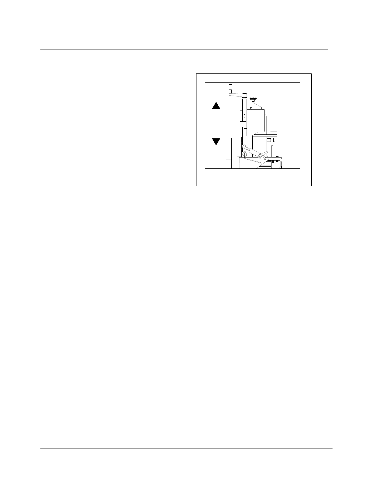
OPERATING THE MACHINE
SQUARE MITRING TO THE FENCE
1 Move the carriage to the front.
2 Fasten the carriage with the blocking
knob, on top of the unit.
3 Turn the saw unit downwards with the
handle on top of the carriage (Fig. 2).
4 The bottom side of the measure pointer
has to be approx. 2 mm under 0 mm.
5 Loosen the blocking knob on top of the
carriage.
6 Let the carriage run backwards behind the
stop.
7 The machine is ready for cutting.
Figure 2
0
1
2
3
4
5
6
7
8
9
10
10
OPERATING THE MACHINE
CUTTING AT AN ANGLE UNDER 45º (625-U)
B.M.O. TILTING THE MOTOR
1 Move the carriage to the front (Fig. 3).
2 Fasten the carriage with the blocking
knob, on top of the unit.
3 Turn the saw unit completely upwards
with the handle on top of the carriage.
4 Keep your right hand at the bottom side
of the motor en loosen the handle with
your left hand. Push the motor with your
right hand, against the 45º stop.
5 Fasten the handle with you left hand.
6 Turn the saw unit downwards with the
handle.
7 The top side of the yellow measure pointer
has to be approx. 2 mm under 0 mm.
8 Loosen the blocking knob on top of the
carriage.
9 Let the carriage run backwards behind the
stop.
10 The machine is ready for cutting.
11 Motor from 45º to 0º; put your right hand
at the bottom side of the motor, loosen the
handle with your left hand. Support the
motor with you right hand till 0º.
Figure 3

11
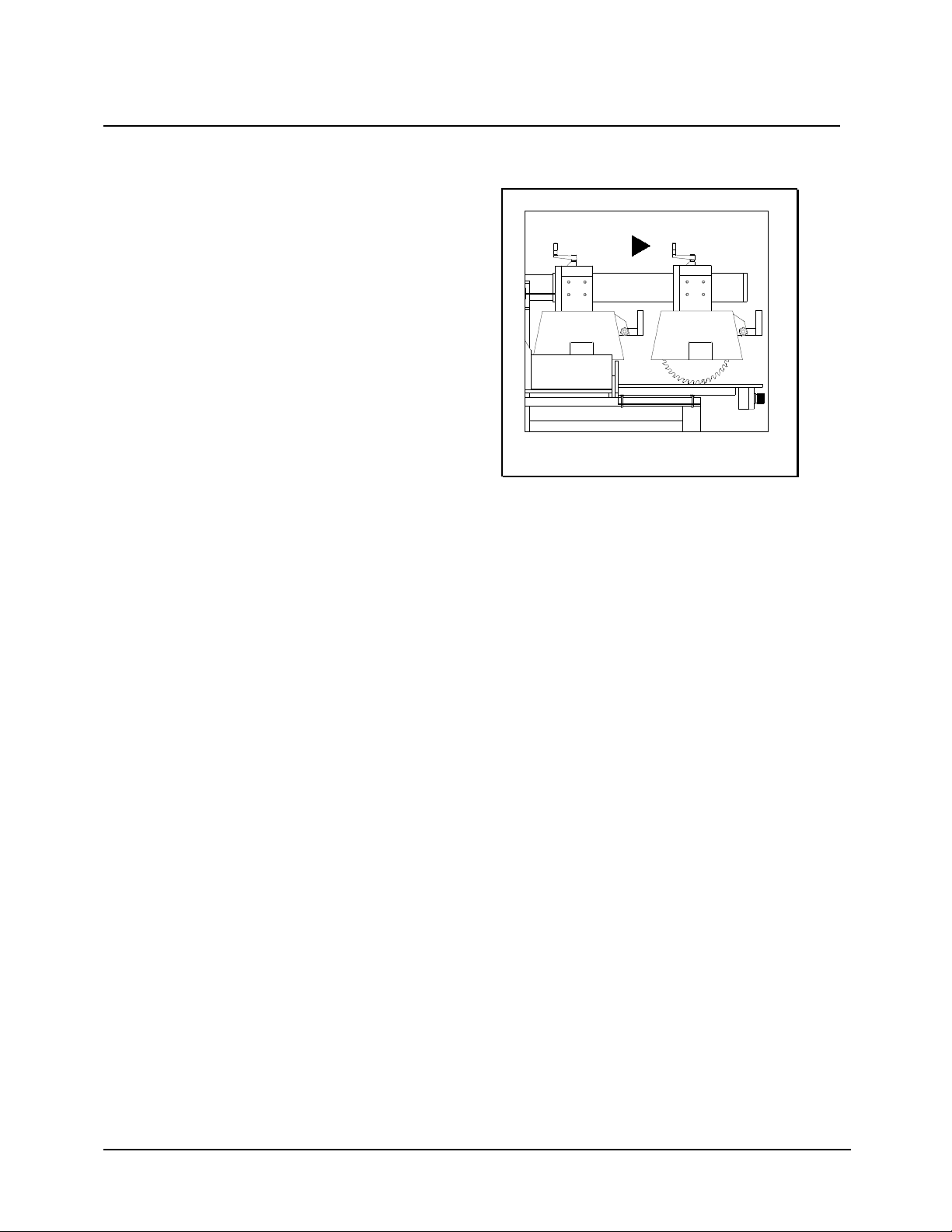
OPERATING THE MACHINE
CUTTING AT AN ANGLE UNDER 45º (625-U)
B.M.O. SWINGING THE ARM
1 Turn the handle at the right backside of
the vertical support backwards (= loosen).
2 Push the arm against the stop of 45º (Fig.
4).
3 Turn the handle on the vertical support
forwards (= fasten).
4 Check the proper adjustment of the
height (has to be 2 mm under 0 mm).
Figure 4

12
OPERATING THE MACHINE
CUTTING AT AN ANGLE BETWEEN 0 AND
45º (625-U)
B.M.O. SWINGING THE ARM (Fig. 5)
1 Move the carriage to the front.
2 Fasten the carriage with the blocking
knob, on top of the unit.
3 Turn the saw-blade slightly upwards.
4 Turn the handle at the backside of the
vertical support a quarter stroke
backwards (= loosen).
5 Set the right angle b.m.o. the measure
scale in the table top.
6 Turn the handle forwards (=tighten).
7 Let the saw-blade touch the topside of the
tabletop.
8 Switch on the machine.
9 Cut a groove.
B.M.O. TILTING THE MOTOR (Fig. 6)
1 Move the carriage to the front.
2 Fasten the carriage with the blocking knob
on top of the unit. Turn up the saw-blade
with the handle on top of the carriage.
3 Set the right angle b.m.o. the measure
scale on the saw unit.
4 Keep your right hand at the bottom side of
the motor. Loosen the handle with your left
hand.
5 Check if the saw-blade is adjusted at the
proper angle.
6 Tighten the handle with your left hand.
7 Let the saw-blade touch the topside of the
tabletop.
8 Switch on the machine.
9 Cut a groove.
Figure 5
Figure 6

13
OPERATING THE MACHINE
COMPOUND ANGLES
1 B.m.o. swinging the arm and tilting of the
motor. Repeat cutting at an angle under
45º or cutting between 0 en 45º.
14
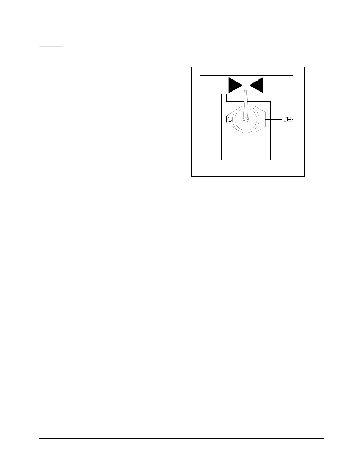
MAINTENANCE
COUNTER BALANCER
Takes the saw-blade automatically back behind
the stop in the 0-position (Fig. 7).
TIGHTEN THE SPRING
1 Put the carriage in the 0-position.
2 Put the delivered plastic key in the hole at
the front side of the counter balancers.
3 Turn the key clockwise (+).
LOOSEN THE SPRING
1 Put the carriage in the 0-position.
2 Push the control spring between the
counter balancer and the support
downwards.
3 The counter balancer can be adjusted at
the proper tension.
Figure 7

15
MAINTENANCE
HANDLE FOR BLOCKING
For blocking of the arm, at the right back side
of the vertical support. Adjust with 10 mm and 5
mm allen key (Fig. 8).
CLAMP TOO LOOSE
1 Handle too much to the front.
2 Loosen the handle backwards.
3 Loosen the block of the handle with a 5
mm allen key.
4 Hold the handle.
5 Turn the adjusting bolt a quarter of a
stroke clockwise with a 10 mm allen key.
6 Tighten the block of the handle with a 5
mm allen key.
CLAMP TOO TIGHT
1 Handle too much to the back.
2 See above. Turn the adjusting bolt a
quarter of a stroke anti-clockwise.
Figure 8

16
MAINTENANCE
ADJUSTMENT ARM TOWARDS THE FENCE
(625-U)
ADJUSTING SQUARNESS
With the adjusting bolts at the back of the
vertical support by using two 13 mm flat keys.
ADJUSTING SWINGING
With the adjusting bolts at the back of the
vertical support by using two 13 mm flat keys.

17
MAINTENANCE
ADJUSTING OF THE SAW-BLADE TO THE
TABLE TOP
ADJUSTING SQUARNESS (Fig. 9)
1 Loosen the adjusting ring at the bottom
slide of the sliding bush. The sliding bush
is positioned at the front side of the
motor.
2 Turn in the bolt between the height
adjusting support and the motor support
at the backside of the carriage.
3 Adjust the saw-blade with a square,
square to the tabletop.
4 Secure the handle on the sliding bush
tightly.
5 Push the lower adjusting ring against the
sliding bush.
6 Re-adjust the bolt at the backside of the
carriage.
ADJUSTING 45º
1 Loosen the adjusting ring at the topside of
the sliding bush.
2 Adjust the saw-blade under 45º with a
bevel.
3 Fasten the handle on the sliding bush
tightly.
4 Push the upper adjusting ring against the
sliding bush.
Figuur 9

18
MAINTENANCE
CLEANING, LUBRICATING AND
GREASING
40 PRODUCTIVE HOURS
Perform following maintenance every 40
productive hours.
1 Clean tracks of the horizontal slideway.
Lubricate slightly.
2 Clean the spindle of the height
adjustment. Grease slightly.
3 Clean the rotating unit at the backside of
the machine (625-U). Grease slightly.
4 Clean the bearings of the carriage.
160 PRODUCTIVE HOURS
Perform following maintenance every 160
productive hours.
5 Wear and tear of cables.
6 Broken or torn parts of the electric circuit.
7 Brake time of saw-blade (= less than 10
seconds).
8 Operations and state of maintenance of
the guard and its fixation.
9 Check dust outlet for free passage.
1000 PRODUCTIVE HOURS
Perform following maintenance every 1000
productive hours.
10 Check tolerance of saw spindle.
11 Check bolt and nut connections of motor.

19
MAINTENANCE
PARTS 625-H
1 Counter balancer
2 Handle height adjustment
3 Safety guard
4 Switch
5 Motor carriage
6 Blocking knob motor carriage
7 Motor
8 Plastic key counter balancer
9 Flat key
10 Main switch
PARTS 625-U
1 Counter balancer
2 Handle height adjustment
3 Safety guard
4 Switch
5 Motor carriage
6 Blocking knob motor carriage
7 Motor
8 Plastic key counter balancer
9 Flat key
10 Main switch
11 Handle
12 Handle sliding bush

20
MAINTENANCE
RADIAL ARM SAW TYPE 625-H
45 732 6 101
9
8
This manual suits for next models
3
Table of contents


