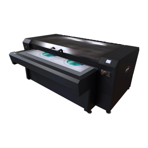
Summa L3214 User manual

L3214 LASER CUTTER
User Manual
Rev 002

FCC Notice
The L3214 laser cutter has been tested and found to comply with the limits for Class A digital
devices, pursuant to Part 15 of the FCC Rules. These limits are designed to provide
reasonable protection against harmful interference when the equipment is operated in a
commercial environment. The cutters generate, use and can emit radio frequency energy,
and if not installed and used in accordance with the instruction manual, may cause harmful
interference to radio communications.
The user assumes the risk of any harmful interference caused by operating the cutters in a
residential area.
Caution!
Changes or modifications, not expressly approved by Summa’s FCC compliance, could void the
user’s authority to operate this equipment.
DOC Notice
The L3214 laser cutter does not exceed the Class A limits for radio noise for digital
apparatus, set out in the Radio Interference Regulations of the Canadian Department of
Communications.
Notice
Summa reserves the right to modify the information, contained in this User Manual, at any time
without prior notice. Unauthorized copying, modification, distribution or display is prohibited.
All rights reserved.
Waste Electrical and Electronic Equipment (WEEE) Directive
Directive 2002/96/EC of the European Parliament and of the Counci. The
symbol (right) is shown on this product. It indicates that the product should
not be placed in municipal waste but should be disposed of separately.
Electrical and electronic equipment can contain materials, which are
hazardous to the environment and human health, and therefore should be
disposed of at a designated waste facility or returned to your retailer for the
appropriate recycling to take place.
If you wish to dispose of this product and the product still functions, please consider
recycling/reusing it by donating it to a charity shop, selling it or exchange parts of it with your
retailer.
Copyright © Summa NV

Registering the laser cutter
Please register the L3214 laser cutter on the following link:
https://www.summa.com/support/product-registration/
Failure to register the L3214 laser cutter may result in a delayed response to warranty and
service inquiries.
Contact Information
All inquiries, comments or suggestions concerning this and other Summa manuals should be
directed to:
Summa, nv
Rochesterlaan 6
B-8470 GISTEL
Belgium
Website
9Hwww.summa.com

Congratulations on Your Purchase of the New L3214 Laser Cutter!
Summa’s professional laser cutting systems have been developed with years of experience in
advanced finishing technology. Summa strives to empower you with laser cutting solutions to
bring exceptional quality, smart processing, extended automation, and unsurpassed accuracy
to your workflow.
Textile is one of the fastest growing markets, where on-demand digital printing proves to be
the game changer many soft signage, sportswear and fashion brands are looking for. Printed
textiles require flawless finishing and absolutely nothing cuts as accurately as lasers do.
The contactless cutting method of laser equipment means no fabric distortion, low to no dust
generation, no tool wear and no fraying of textiles or fabrics thanks to perfectly sealed edges.
Even most intricate details are a breeze to cut with Summa laser cutting technology.
Discover the many other advantages Summa laser cutting technology has to offer in this
manual. Also, an overview of main components of the L3214, operating procedures and safety
precautions are being explained in this manual.
All information in this manual must be read and understood before any attempt to operate the
machine is made.
This manual was compiled based on the following revisions:
Firmware 3011

Table of Contents
1Safety......................................................................................................................7
1.1 Safety......................................................................................................................7
1.1.1 General....................................................................................................................7
1.1.2 Symbols used in this manual ..................................................................................7
1.1.3 Safety symbols on the machine..............................................................................8
1.1.4 Safety precautions ..................................................................................................9
1.1.4.1 Danger area during operation.................................................................................9
1.1.4.2 Safety precautions related to movement ................................................................9
1.1.4.3 Safety precautions related to the built-in laser........................................................9
1.1.4.4 Safety precautions related to the system components.........................................10
1.1.4.5 Safety precautions related to the extraction system.............................................10
1.1.4.6 Safety precautions related to the material ............................................................10
1.1.4.7 Safety precautions related to fire ..........................................................................10
1.1.5 Safety features......................................................................................................10
1.1.5.1 Emergency stop buttons .......................................................................................10
1.1.5.2 Safety covers ........................................................................................................11
1.1.6 Personal protective equipment .............................................................................11
1.2 Operating environment.......................................................................................11
2Laser cutting system components....................................................................12
2.1 Laser Cutter.........................................................................................................13
2.1.1 Touch control panel...............................................................................................14
2.1.1.1 Home screen.........................................................................................................14
2.1.1.2 Settings screen .....................................................................................................15
2.1.1.3 Laser Test Fire Screen..........................................................................................16
2.1.1.4 Media Area Screen ...............................................................................................17
2.1.2 Conveyor system ..................................................................................................18
2.1.3 Finger safety conveyor cover................................................................................18
2.1.4 Safety cover lid......................................................................................................18
2.1.5 Emergency stop buttons .......................................................................................18
2.1.6 Vision camera gantry ............................................................................................18
2.1.7 Pressure rollers.....................................................................................................18
2.1.8 Feed button...........................................................................................................18
2.1.9 Light switches........................................................................................................19
2.1.10 ON/OFF buttons....................................................................................................19
2.1.11 Ethernet connection..............................................................................................19
2.1.12 Main power switch.................................................................................................19
2.2 Edge detection unwinder ...................................................................................20
2.2.1 Safety Information.................................................................................................20
2.2.1.1 General..................................................................................................................20
2.2.1.2 Residual Risks ......................................................................................................20
2.2.1.3 Noise.....................................................................................................................20
2.2.2 Positioning the unwinder.......................................................................................21
2.2.3 Components..........................................................................................................22
2.2.3.1 Emergency stop buttons .......................................................................................22
2.2.3.2 Control panel.........................................................................................................23
2.2.3.3 Droop sensor and tension bar...............................................................................24
2.2.3.4 Edge detection sensor ..........................................................................................26
2.3 Air pressure media shaft (optional) ..................................................................28
2.4 Loading the roll of material on the unwinder...................................................29
2.5 Water Chiller........................................................................................................30
2.5.1 General Description ..............................................................................................30
2.5.2 Temperature..........................................................................................................30
2.5.3 Safety precautions ................................................................................................30
2.6 Vacuum and fume extraction system ...............................................................31
2.6.1 Extraction pump ....................................................................................................31
2.6.2 Vacuum pump.......................................................................................................31

3Starting up the laser cutter ................................................................................32
4Maintenance ........................................................................................................33
4.1 Laser cutter..........................................................................................................33
4.1.1 Optical components ..............................................................................................34
4.1.1.1 Cleaning the static mirror......................................................................................35
4.1.1.2 Cleaning the travelling mirror................................................................................35
4.1.1.3 (Un)Installing the static and travelling mirrors.......................................................36
4.1.1.4 Cleaning the combining mirror..............................................................................37
4.1.1.5 Cleaning the cutting head lens..............................................................................38
4.1.1.6 Cleaning the cutting head mirror...........................................................................41
4.1.2 Pneumatics............................................................................................................43
4.1.2.1 Cleaning the nozzle...............................................................................................43
4.1.2.2 Setting the nozzle height.......................................................................................44
4.1.2.3 Adjusting airflow....................................................................................................45
4.1.2.4 Emptying the water collection bowl.......................................................................45
4.1.3 Cutting head drive belt..........................................................................................46
4.1.4 Conveyor planks ...................................................................................................47
4.1.5 Water-cooled laser unit.........................................................................................47
4.2 Extraction system ...............................................................................................48
4.3 Chiller...................................................................................................................49
4.3.1.1 Water level ............................................................................................................49
4.3.1.2 Water quality .........................................................................................................50
4.3.1.3 Water pipes...........................................................................................................50
4.3.1.4 Air filter..................................................................................................................52
4.4 Maintenance Overview .......................................................................................53
5Consumables.......................................................................................................55
6Troubleshooting..................................................................................................56
6.1 Error Messages ...................................................................................................57
7GoCare .................................................................................................................58
8Go Produce Laser Edition..................................................................................59

L3214 Laser Cutter User’s Manual
Safety 7
1SAFETY
1.1 Safety
1.1.1 General
The manufacturer has no direct control over the machine operation and application. Proper
safety practice is the sole responsibility of the owner, user, and operator.
All instructions and safety warnings in this manual are based upon the use of this machine
under proper operating conditions without alterations from the original design.
Any use of the laser cutter that is beyond the capabilities of the combination laser
source/material is considered as improper use and may result in injury and/or serious damage
to the machine and will lead to loss of warranty.
The installation of the machine, accessories, and spare parts must not be done by untrained
or unauthorized persons. Also, the described maintenance procedures need to be followed and
performed by trained personnel.
1.1.2 Symbols used in this manual
Warning with dark (red) symbol: Refers to immediate threat that can cause
serious injuries and effects on health and safety.
Warning with light (yellow) symbol: Refers to a dangerous situation that can
cause injuries and serious damage to the machine.
Attention with dark (red) symbol: Refers to useful information to prevent
damage to the equipment and prolong the service life of the machine.
Attention with light (yellow) symbol: Refers to useful tips to enhance user-
friendliness and make the work significantly easier.
Note: Can be considered as a general tip, something that is useful to know.

L3214 Laser Cutter User’s Manual
Safety 8
1.1.3 Safety symbols on the machine
Safety labels are used on some parts of the machine. They are explained below.
Caution
Servicing instructions are for use by qualified service personnel only.
To reduce the risk of electric shock, do not open the equipment and do
not perform any servicing other than that contained in the operating
instructions unless you are qualified to do so.
Unplug this equipment when not used for an extended period of time.
Caution
Class 1 Laser Product.
Class 4 invisible laser radiation when open.
Avoid eye or skin exposure to direct or scattered radiation.
Class 2 laser pointer. Do not stare into the beam.
Caution
Moving parts. Risk of trapping. Keep hands, clothing, jewellery, and hair
away.
Caution
This equipment should only be used in a well ventilated area.
Do not cover ventilation openings.
Periodic maintenance required.
Only use a CO2fire extinguisher on this equipment.
Compressed air hazard. Ensure that the air supply to the machine is
disabled before disconnecting tubes.
Consult the user’s manual.
Make sure to observe all the caution labels on the machine.

L3214 Laser Cutter User’s Manual
Safety 9
1.1.4 Safety precautions
WARNING: This equipment is not suitable for use in locations where children are
likely to be present.
1.1.4.1 Danger area during operation
The general danger area is the yellow area: the complete area where the conveyor is moving
and the fabric roll is in motion. Anyone not operating the machine should keep a distance
around the machine of at least one meter. Only the trained operator or fully trained personnel
can be in this area. When the laser cutter is operating, do not leave it unattended at any time.
1.1.4.2 Safety precautions related to movement
WARNING: There is a risk of injury from being caught or trapped in moving
machine parts. Keep hands, hair, clothing and jewellery away from moving parts.
Do not wear jewellery, loose clothing, scarves, open jackets or shirtsleeves.
1.1.4.3 Safety precautions related to the built-in laser
The laser emits invisible class 4 laser radiation; avoid skin exposure to direct or scattered laser
light and do not stare into the laser beam. Wear laser safety goggles.
WARNING: Safety goggles must be worn.
Any person or organization performing any modification to the L3214 laser cutting system is
responsible for ensuring the reclassification and relabelling of the laser product.

L3214 Laser Cutter User’s Manual
Safety 10
1.1.4.4 Safety precautions related to the system components
When closing the safety cover, ensure that no fingers or other items can be trapped between
the safety cover and the side pod. When the safety cover is lifted, care must be taken to avoid
bumping your head against it. The electrical enclosure (i.e. doors and cover pods, etc.) must
only be opened by trained service personnel. The L3214 laser cutting system must not be
operated with its shutter, guard, protective housings, or any of the safety interlocks removed.
1.1.4.5 Safety precautions related to the extraction system
Before commencing any cutting procedure ensure that the fume extraction system is in good
working order and operates correctly. Ensure that any fumes are extracted in accordance with
health and safety requirements.
1.1.4.6 Safety precautions related to the material
The L3214 laser cutter can process a broad range of materials. Choose only material types
that do not generate harmful emission during the cutting process. Check with the material
supplier or manufacturer before cutting. The following materials are not suitable for being
laser-cut:
•Leather and artificial leather that contains chromium (VI)
•Carbon fibres (Carbon)
•Polyvinyl chloride (PVC)
•Polyvinyl butyral (PVB)
•Polytetrafluorethylenes (PTFE / Teflon)
•Beryllium oxide
•Any materials containing halogens (fluorine, chlorine, bromine, iodine and astatine), epoxy
or phenolic resins.
WARNING: Respiratory equipment must be worn for airborne dust particles.
1.1.4.7 Safety precautions related to fire
The cutting area must be provided with a carbon dioxide fire extinguisher and any relevant
personnel must be trained to use it in case of emergency.
1.1.5 Safety features
1.1.5.1 Emergency stop buttons
Pressing an emergency stop button will shut down the machine immediately. The current
cutting job will be lost. The system (and preferably the software as well) will have to be
rebooted in order to restart the cutting process.

L3214 Laser Cutter User’s Manual
Safety 11
1.1.5.2 Safety covers
When the safety cover lid of the cutting area or the conveyor safety cover is opened, the laser
stops firing and the cutting job is paused. A warning on the touch control panel pops up,
prompting the operator to close the cover. The machine will resume operation when the covers
have been closed.
1.1.6 Personal protective equipment
The required safety equipment depends on the material that needs to beis processed. When
operating or servicing the machine, the operator should wear appropriate protective
equipment. This can include:
•Protective work clothing
•Respirator mask, in case of toxic fumes
•Safety goggles: when processing the material, harmful particles can be generated.
1.2 Operating environment
Environmental conditions can significantly affect the machine’s performance. Most
restrictions or recommendations for the ideal operating environment are already described in
the site preparation document. The environmental conditions of the machine (without media)
are as follows:
Operating Temperature
15 to 32C
59 to 90F
Storage temperature
-30 to 70C
-22 to 158F
Relative humidity
10 - 85 %, non-condensing
It is possible that the environmental conditions of the used media are stricter than those of
the machine itself. Please refer to the documentation about the used media. Also, make sure
that the media has had enough time to acclimatize.

L3214 Laser Cutter User’s Manual
Laser cutting system components 12
2LASER CUTTING SYSTEM COMPONENTS
Laser cutter
Edge detection unwinder
Water chiller
Extractor fans (vacuum and fume extraction)
1
2
3
4

L3214 Laser Cutter User’s Manual
Laser cutting system components 13
2.1 Laser Cutter
(1) Touch control panel
(2) Conveyor system
with vacuum and fume extraction system underneath
(3) Finger safety conveyor cover
(4) Safety cover lid
(5) Emergency stop buttons
(6) Vision camera gantry
(7) Pressure rollers
(8) Feed button
(9) Light switch camera gantry and cutting area
(10) ON/OFF buttons
(11) Vision cameras connection
(12) Unwinder connection
(13) Vision gantry light connection
(14) Ethernet connection
(15) Main power switch
1
2
3
4
5
5
5
6
7
7
rear of the laser cutter
5
8
9
10
12
11
13
14
15

L3214 Laser Cutter User’s Manual
Laser cutting system components 14
2.1.1 Touch control panel
The touch control panel is a unique interface system providing detailed cutter information and
offering a flexible and powerful control of the cutter’s configuration.
If applicable, tips or advice will be shown here. After a certain period of inactivity of the panel,
the screensaver appears. Touching the screen once disables the screensaver. After starting
up the machine, the home screen is initialised.
2.1.1.1 Home screen
The screen is split into two sections. The working parameter limits of the machine are displayed
in mm. On the top right, the cutter’s status is indicated.
Use the arrow keys in the left section to move the cutting head around the
cutting area. Use the arrow keys in the right section to control the conveyor
movement: forward (down arrow) and backward (up arrow). The up arrow is
disabled by default: this is only available when performing maintenance.
Tap to pause the cutting process.
Tap to cancel the current cutting job. This button becomes available after
the system has been paused and the cutting head has stopped moving.
Tap to access the Media Area screen. This button is only available when the
cutter is idle and not partway through a job.
Tap to access the Settings screen.

L3214 Laser Cutter User’s Manual
Laser cutting system components 15
2.1.1.2 Settings screen
This screen allows viewing and changing the basic settings.
2.1.1.2.1 Parameters
•Quality Mode: The system supports three different quality modes:
Standard
,
Quality
, and
Fine Detail
. You can switch between these modes by clicking the current one.
NOTE: Cutting in
Fine Detail
quality mode requires a low speed setting.
•Fans Manual:
TRUE
or
FALSE
. Tap the current setting to change it.
oVac (vacuum): Use and to change vacuum intensity, displayed inbetween
these buttons. The system does not allow the vacuum setting to exceed the extraction
setting.
oExt (extraction): Use and to change extraction intensity, displayed inbetween
these buttons.
•Auto Fans:
TRUE
or
FALSE
. Tap the current setting to change it.
•Laser Armed:
TRUE
or
FALSE
. Tap the current setting to change it.
•Laser Power: Tap the current setting to change it.
•Sequence Velocity: The speed at which the cutting head moves. Tap the current setting to
change it.
Tap to return to the home screen.
Tap to access the Laser Test Fire screen (see p. 16).
Tap to immediately cut off the media at the front of the working area.
Tap to immediately cut off the media at the back of the working area.

L3214 Laser Cutter User’s Manual
Laser cutting system components 16
2.1.1.3 Laser Test Fire Screen
This screen is used to test-fire the laser and to cut straight lines manually.
Tap to activate the move-and-fire action, then use the arrow keys in the
left section to move the head around the cutting area while the laser is
firing. Tap again to stop the move-and-fire action.
Tap to fire the laser once in its current position (“spot-fire”).
Tap to return to the Settings screen. In case a move-and-fire actie is on-
going, it will be stopped.
The speed at which the cutting head moves during the move-and-fire
action. Tap to change the current setting.
Displays the pulse time of the laser for the spot-fire action. Tap to change
the current setting.
Displays the laser power intensity (in %). Tap to change the current
setting.

L3214 Laser Cutter User’s Manual
Laser cutting system components 17
2.1.1.4 Media Area Screen
You can create a smaller cutting window within the main bed area. This is very useful when
you’re cutting on standard format cardboard, paper, or when cutting a fabric sample. It allows
you to place the material on the cutting bed and then set the working area according to the
dimensions of the material.
1. Use the arrow keys in the left section to move the cutting head to the bottom right corner
of the material.
2. Press to confirm.
3. Use the arrow keys in the left section to move the cutting head to the upper left corner of
the material.
4. Press to confirm.
NOTE: Setting the upper left corner of the working area is not required. If
you do not set the upper left corner, the system will automatically use the
remainder of the bed area.
The new working area has now been set and the cutting head moves back to the bottom
right corner of the working area. The working area values are shown below the Summa
logo.
Tap to confirm and apply your changes.
Tap to reset to the default (entire) working area.

L3214 Laser Cutter User’s Manual
Laser cutting system components 18
2.1.2 Conveyor system
The conveyor system, equipped with blade planks, transports the material through the working
area and then out of the machine. The material is held down by the vacuum/extraction system
underneath the conveyor bed, resulting in a clean cut and precise material transport.
ATTTENTION: Do not lean on the conveyor planks as this can cause deflection.
2.1.3 Finger safety conveyor cover
More information can be found in chapter 1.1.5.2
Safety covers
on page 11.
2.1.4 Safety cover lid
More information can be found in chapter 1.1.5.2
Safety covers
on page 11.
2.1.5 Emergency stop buttons
More information can be found in chapter 1.1.5.1
Emergency stop buttons
on page 10.
2.1.6 Vision camera gantry
The L3214 laser cutter is equipped with the Vision camera gantry. The Vision camera system
uses integrated cameras to scan marks, black outlines, or barcodes, fast and accurately. It is
also possible to scan, feed and cut at the same time. This camera system supports the following
advanced work methods:
•Cut-to-Frame (also known as Fixed Size cutting)
•Barcode workflow (requires Pro Pack)
•Trace & Cut
•Cut-on-the-Fly
More information on the advanced work methods can be found in the Go Produce Laser Edition
user manual.
2.1.7 Pressure rollers
There are two pressure rollers available: one on the front and one on the rear of the conveyor
bed. They should be placed in the lower recess to improve traction of the material on the
conveyor when cutting.
2.1.8 Feed button
When this button is pressed, the conveyor will immediately advance a preset distance (value
in mm). This distance can only be set in service mode.

L3214 Laser Cutter User’s Manual
Laser cutting system components 19
2.1.9 Light switches
Two light switches to switch on or off the light on the Vision gantry and in the cutting area.
2.1.10 ON/OFF buttons
WARNING: Using the OFF button will not cut all the power in the machine! Before
opening any covers to perform service or maintenance, always switch off power
using the main power switch.
2.1.11 Ethernet connection
Summa provides a computer in the right cabinet of the cutter, connected to the Ethernet
connection on the rear of the cutter.
2.1.12 Main power switch
WARNING: Using the OFF button will not cut all the power in the machine! Before
opening any covers to perform service or maintenance, always switch off power
using the main power switch.

L3214 Laser Cutter User’s Manual
Laser cutting system components 20
2.2 Edge detection unwinder
A motorised unwinder eliminates fabric distortion while cutting by securing a constant and
stable fabric feed onto the cutting bed. As the roll unwinds, a loop is created to relax the
material, reducing distortion, and secure an accurate cut. This loop is kept constant with the
use of the droop sensor or the tension bar.
2.2.1 Safety Information
2.2.1.1 General
The unwinder is used for feeding the laser system with synthetic or natural materials. Using
the unwinder for any other purpose is forbidden. Do not leave any safety covers open when
operating.
WARNING: Frequent heavy lifting and handling of the rolls of fabric can cause back
injuries. Use appropriate lifting and handling tools or ask assistance to reduce this
risk.
Always turn off the unwinder before opening the safety covers or investigating a malfunction.
Only authorised personal may then switch on the unwinder to investigate the problem.
Always turn off the unwinder before opening the electrics cabinet.
Do not move the unwinder when in operation. Space should be kept clear at both ends of the
unwinder to allow for full travel of the upper frame. Do not lean anything against the unwinder.
WARNING: There is a risk of injury from being caught or trapped in moving
machine parts. Keep hands, hair, clothing and jewellery away from moving parts.
Do not wear jewellery, loose clothing, scarves or open jackets or shirtsleeves.
2.2.1.2 Residual Risks
The upper frame of the unwinder travels laterally if required to supply the laser cutter with
fabric correctly. The timing of these movements cannot be anticipated, so great care should
be taken when being around the unwinder during operation. Operator presence is not required
during roll feeding. The lateral travel of the feed mechanism has a limited range.
2.2.1.3 Noise
The noise level does not exceed 70 dBA.
Table of contents
Other Summa Cutter manuals

Summa
Summa SummaCut D160SE User manual

Summa
Summa L1810 User manual

Summa
Summa S CLASS User manual

Summa
Summa S Class 2 OPOS-CAM User manual

Summa
Summa S Class 2 OPOS-CAM User manual

Summa
Summa SummaSign D500 User manual

Summa
Summa SUMMACUT User manual

Summa
Summa S One Series User manual

Summa
Summa S Class 2 OPOS-CAM User manual

Summa
Summa S 75 User manual

Summa
Summa S2 SERIES User manual

Summa
Summa L1810 User manual

Summa
Summa S3 Series User manual

Summa
Summa SummaCut D120 User manual

Summa
Summa S CLASS User manual

Summa
Summa SummaSign Pro SL D-series User manual

Summa
Summa SummaCut D120 User manual

Summa
Summa L1810 2nd generation User manual

Summa
Summa L1810 User manual