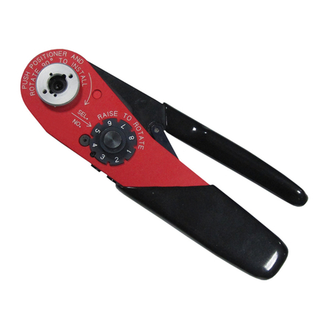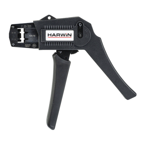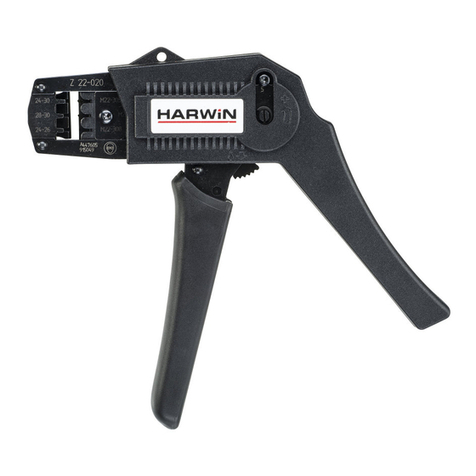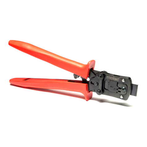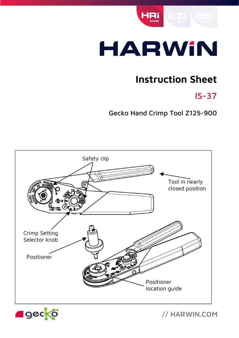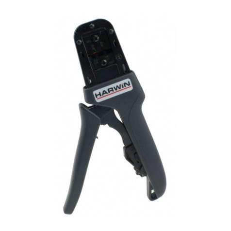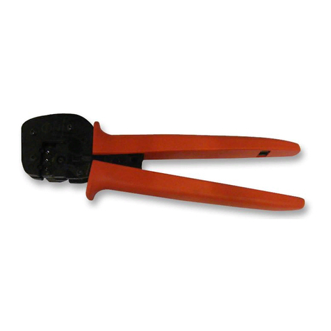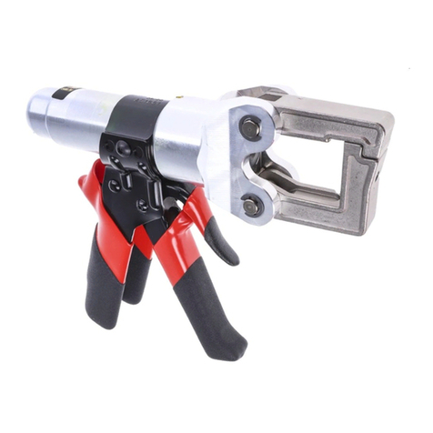
Instruction Sheet for Gecko-MT Hand Crimp Tool Z125-90 /904 (MH820)
2. Cut the end of the cable to be terminated so that there is a clean cut end (Figure A). Strip
the cable to the correct length (Figure B). We recommend that when the wire is stripped, it
is clamped or supported close to the stripping area - this will prevent insulation slippage.
Suitable wire strippers (such as a PTFE wire stripper) must be used. This should result in all
the strands lying together neatly. If the lay of the strands is disturbed, it may be re-imposed
with a slight twist.
Figure A - Clean cut end Figure B - Strip wire
. Position the crimp contact fully into the positioner, with the crimp barrel uppermost.
4. Load the termination end of the cable into the crimp barrel of the socket. Ensure the wire is
fully inserted, with all strands in place (see Figure C, contact may not be as shown).
Figure C – Wire assembled to contact
Ca tion: Wear Nitrile/Latex powder free gloves or Finger cots when
handling contacts to prevent hands from contaminating contacts.
5. Squeeze the handles of the crimp tool fully together, until the ratchet releases. The handle
will return to the open position. Remove the crimped contact and wire. Crimp joints should
be checked for:
a. Correct combination of cable, tool setting and crimp termination.
b. Correct form of indents and location of crimp.
c. Freedom of fracture, rough edges and flash.
d. Adequate insertion of all conductor strands in the crimp barrel.
e. Absence of damage to the conductor or the insulation.
ASSEMBLY PROCEDURE
Contacts are assembled to housings using the Assembly Tool Z125-905. See Instruction Sheet IS-
47 for details on assembly.
