162-072012 Digital VT Page 9 of 12
3. Vacuum Gauge Operation
All Hastings gauge tubes are shipped with a protective cap or cover at the evacuation port to reduce
contamination and prevent damage to the internal thermopile elements. Once the protective cap or cover is
removed, a tube can be installed in any convenient position in the vacuum system without adversely affecting
calibration or performance. The recommended orientation is with the tube vertical and its stem down. This
will aide in preventing condensable materials from remaining in the gauge tube.
3.1 AC Input Power
The Digital VT Power Supply input is rated as consuming 0.25 Amps @ 120VAC.
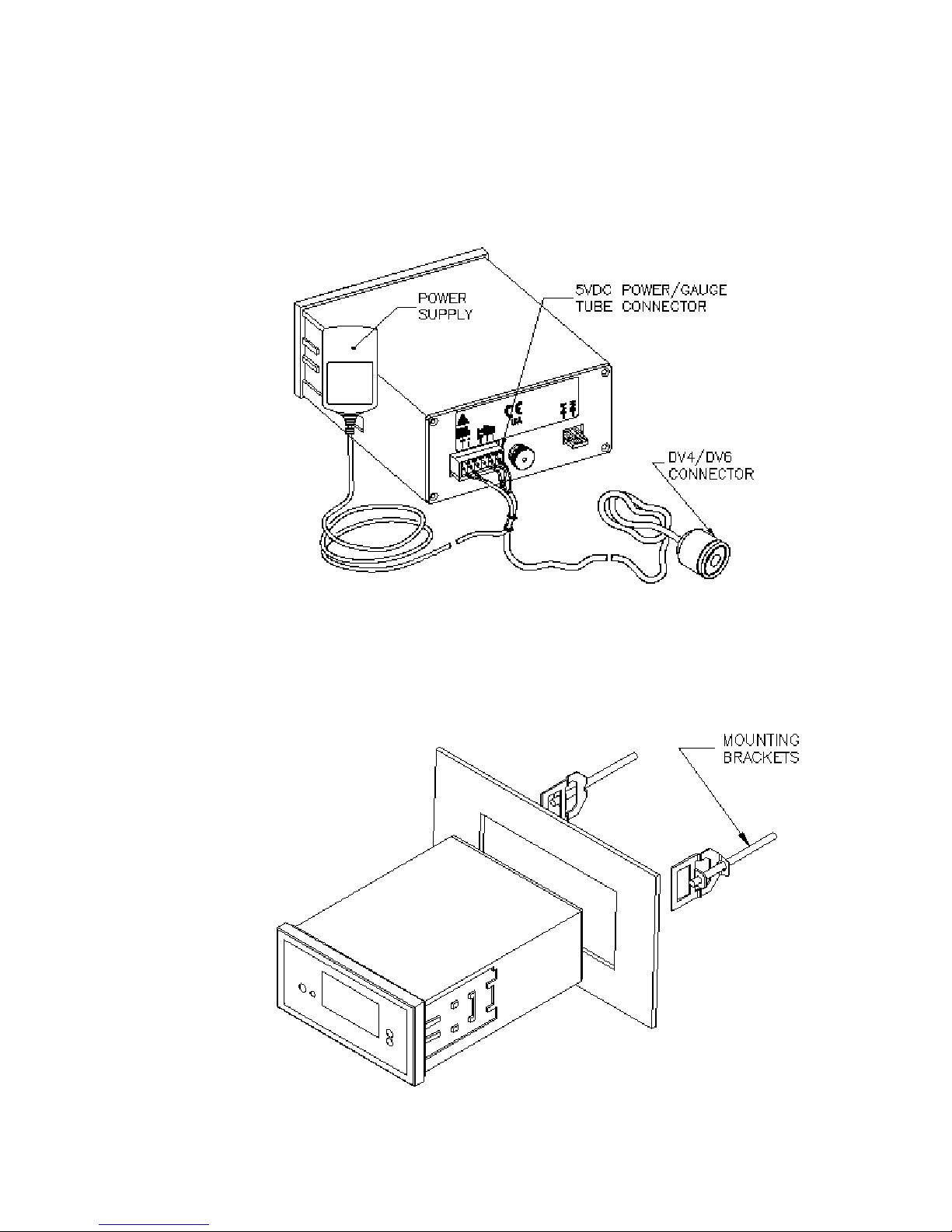
The Power/Gauge Tube Cable is assembled at the factory as shown in Fig. 4. It requires no further
wiring to be performed. To operate the Digital VT, plug the Power/Gauge Tube Cable into the
connector located in the rear of the Digital VT. Connect the plug of the power supply into a single
phase 100-230 VAC. 50/60 Hz power source
3.2 Quick Start
1. Plug Digital VT power supply into a 100-230 Hz outlet source.
2. Connect a DV4 or DV6 gauge tube to the Octal Socket cable assembly that is attached to the rear of
the Digital VT.
3. The CPU will do a self check/initialization. The digital display should count up and stop
momentarily at FFF. (Note: If the digital display shows a "- - -", this means the instrument is out of
range or gauge tube is unplugged.)
4. The Torr and mTorr LED’s should also momentarily illuminate.
5. After the CPU is operating, and the self check/initialization is complete, the display will indicate the output
of the DV4 or DV6 tube.
6. No other operator action is required.
7. For a more accurate reading from the DV4 or DV6 tubes, refer to Section 3.7 and perform a calibration of
unit.
3.3 Pressure Measurement
Connect the gauge tube cable’s octal socket onto the octal base of a gauge tube installed in vacuum system.
The gauge will display the system pressure on the Digital VT. To check the accuracy of the gauge, perform the
required operations as specified in section 3.7.
3.4 Operation and Performance
The Digital VT will function right “out of the box”. For maximum accuracy refer to section 3.7 and perform
the calibration procedure.
The simplest and quickest way of checking the operation and performance of a gauge and/or gauge tube, is
to keep in hand a new or known-good gauge tube on hand for use as a Reference.
To check operation, install both the Reference and suspect gauge tubes in a common vacuum system
(locate the gauge tubes as close as possible to each other), then evacuate the system until a stable base pressure
is obtained. Alternately connect the vacuum gauge to each gauge tube and record its pressure readings. If the
gauge tube-under-test produces a higher pressure reading than the Reference gauge tube, this indicates a
calibration shift and is usually the result of contamination (particulate, oil, or other chemical deposits). You
can try to restore calibration of the contaminated gauge tube by cleaning it internally with an appropriate
solvent such as high-purity isopropyl alcohol (flood the interior cavity of gauge tube gently with solvent and