Hastings HFM-D-301 User manual

INSTRUCTION MANUAL
HFM-D-301/305 FLOW METERS
HFC-D-303/307 FLOW CONTROLLERS
TELEDYNE
HASTINGS
INSTRUMENTS

163-112009 HFM-HFC-D_301/303/305 and 307 Page 2 of 43
Manual Print History
The print history shown below lists the printing dates of all revisions and addenda created for this
manual. The revision level letter increases alphabetically as the manual undergoes subsequent updates.
Addenda, which are released between revisions, contain important change information that the user
should incorporate immediately into the manual. Addenda are numbered sequentially. When a new
revision is created, all addenda associated with the previous revision of the manual are incorporated into
the new revision of the manual. Each new revision includes a revised copy of this print history page.
Revision A (Document Number 163-042008)........................................................................... April 2008
Revision B (Document Number 163-092008).................................................................. September 2008
Revision C (Document Number 163-072009) ............................................................................ July 2009
Revision D (Document Number 163-082009) .......................................................................August 2009
Revision E (Document Number 163-112009).................................................................. November 2009
Visit www.teledyne-hi.com for WEEE disposal guidance.
Hastings Instruments reserves the right to change or modify the design of its equipment without any
obligation to provide notification of change or intent to change.
The instruments described in this manual are designed for Class 2 installations
in accordance with IAW/IPC standards
CAUTION:
CAUTION:
The ins truments described in this manual are designed for INDOOR use only.
The ins truments described in this manual are av ailable with multiple pin-outs .
Ensure that all electrical connections are correct.
CAUTION:

163-112009 HFM-HFC-D_301/303/305 and 307 Page 3 of 43
Table of Contents
1. GENERAL INFORMATION............................................................................................................................................ 4
1.1. Features.......................................................................................................................................................................... 4
1.2. Specifications................................................................................................................................................................. 5
1.3. Other Accessories.......................................................................................................................................................... 6
2. INTRODUCTION..............................................................................................................................................................7
3. INSTALLATION & OPERATION.................................................................................................................................. 8
3.1. Receiving Inspection.....................................................................................................................................................8
3.2. Power Requirements.....................................................................................................................................................8
3.3. Output Signal ................................................................................................................................................................. 8
3.4. Quick Start ..................................................................................................................................................................... 8
4. SETUP................................................................................................................................................................................. 9
4.1. Mechanical Connections...............................................................................................................................................9
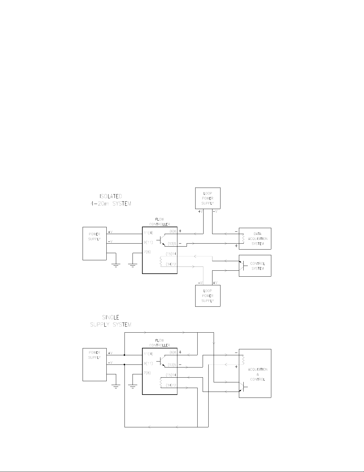
4.2. Electrical Connections..................................................................................................................................................9
5. DIGITAL COMMUNICATION.....................................................................................................................................14
5.1. Basics.............................................................................................................................................................................14
5.2. Operating States..........................................................................................................................................................15
5.3. Digital Control ............................................................................................................................................................. 15
6. OPERATION....................................................................................................................................................................20
6.1. Operating Conditions.................................................................................................................................................. 20
6.2. Zero Check ...................................................................................................................................................................20
6.3. High Pressure Operation ............................................................................................................................................20
6.4. Blending of Gases........................................................................................................................................................22
6.5. Controlling Other Process Variables ........................................................................................................................ 22
6.6. Command Input ........................................................................................................................................................... 23
6.7. Valve Override Control............................................................................................................................................... 23
7. THEORY OF OPERATION...........................................................................................................................................24
7.1. Overall Functional Description .................................................................................................................................24
7.2. Sensor Description ......................................................................................................................................................24
7.3. Sensor Theory .............................................................................................................................................................. 25
7.4. Base ...............................................................................................................................................................................26
7.5. Shunt description ........................................................................................................................................................ 28
7.6. Shunt Theory................................................................................................................................................................ 28
7.7. Control Valve ............................................................................................................................................................... 32
8. MAINTENANCE..............................................................................................................................................................34
8.1. Authorized Maintenance ............................................................................................................................................34
8.2. Troubleshooting...........................................................................................................................................................34
8.3. End Cap Removal.........................................................................................................................................................38
9. GAS CONVERSION FACTORS....................................................................................................................................39
10. REFERENCES .................................................................................................................................................................42
11. WARRANTY AND REPAIR .......................................................................................................................................... 43
11.1. Warranty Repair Policy ..............................................................................................................................................43
11.2. Non-Warranty Repair Policy ......................................................................................................................................43

163-112009 HFM-HFC-D_301/303/305 and 307 Page 4 of 43
1. General Information
The Hastings mass flow meter (HFM-D-301/305) and controllers (HFC-D-303/307) are intrinsically linear
and are designed to accurately measure and control mass flow over the range of 5 sccm to 2500 slm.
Hastings mass flow instruments do not require any periodic maintenance under normal operating
conditions with clean gases. No damage will occur from the use of moderate overpressures (~500
psi/3.45MPa) or overflows. Instruments are normally calibrated with the appropriate standard
calibration gas (nitrogen) then a conversion factor is used to adjust the output for the intended gas.
Calibrations for other gases, such as oxygen, helium and argon, are available through special order.
1.1. Features
•LINEAR BY DESIGN. The 300 series is intrinsically linear. The output of the sensor has a non-linearity
less than 2% before the curve fit. This minimizes the density driven errors that occur when gases
other than the calibration gas are measured.
•CURVE FIT CORRECTION. The Digital 300 series uses a curve fitting technique to remove any residual
non-linearity from the system to improve the overall accuracy. This significantly improves the % of
Reading errors when flow rates are at a small fraction of the controller’s full scale flow.
•FLEXIBLE POWER REQUIREMENTS. The Digital 300 series can operate with any power supply capable
of providing 15 -30 vdc between the high and low supply pins. Bipolar ±12 vdc, ±15 vdc or unipolar 24
vdc are all acceptable.
•DIGITAL COMMUNICATIONS. The Digital 300 series can communicate or be controlled via an RS232
port or a RS485 bus. Baud rates up to 19.2k baud are supported.
•ANALOG EMULATION. The Digital 300 series instrument can be set up to mimic an analog instrument.
In this configuration the flow output is available as an analog signal and flow controllers will respond
to analog commands.
•AUTO-ZERO. The Digital 300 series of flow controllers can re-zero automatically. This feature is
enabled by default at the factory. Auto-zeroing will occur whenever the command signal is set to
zero for more than 3 minutes. This feature removes most temperature driven zero shifts.
•LOW TEMPERATURE DRIFT. The temperature coefficient of span for the Digital 300 series is less than
0.05% of Reading per °C. The temperature coefficient of zero is negligible when the auto-zero system
is active.
•CURRENT LOOP. The 0-20 mA or 4-20 mA option gives the user the advantages of a current loop
output to minimize environmental noise pickup.
•NO FOLDOVER. The output signal is linear for very large over flows and is monotonically increasing
thereafter. The output signal will not come back on scale when flows an order of magnitude over the
full scale flow rate are measured. This means no false acceptable readings during leak testing.

163-112009 HFM-HFC-D_301/303/305 and 307 Page 5 of 43
1.2. Specifications
Accuracy.................................................................................................... ±(0.2% (F.S.) + 0.5% of reading)
Repeatability..............................................................................................................................±0.1% of F.S.
Maximum Pressure...........................................................................................................500 psi [3.45 MPa]
Maximum Pressure................................................................................ 1000 psi [6.9 MPa] (301/303 only)
................................................................................................................................. (with high pressure option)
Pressure Coefficient .............................................................................. (Span) 0.01%/psi (N2)(0-50 psig)
........................................................................................................... See pressure section for pressure errors
Operating Temperature................................................................ 0-50°C in non-condensing environment
Temperature Coefficient of Zero............................................................ N/A for controller with Auto-zero
......................................................................................................................... (zero) < 0.25%/°C of Full Scale
Temperature Coefficient of Span.........................................................................maximum ±500 ppm/°C
Leak Integrity......................................................................................................................<1x10⁻⁸ std. cc/s
Standard Output.............................................................................................0-5 VDC. (Load min 2k Ohms)
Optional Output................................................................................................ 0-10 VDC 0-20 mA, 4-20 mA
Power Requirements ............................................................................... 15-30 VDC @ 5.5 watts (meters)
.......................................................................................................................................@ 7.5 watts (controller)
..................................................................................................................................Class 2 power 150 VA max
Wetted Materials.............................................................. 302/304 & 316 stainless steel, nickel 200, Viton
.....................................................................................................................................Kalrez® (controller only)
Attitude Sensitivity of Zero ..........................................................................................Zero < 0.7% of F.S.
...............................................................................................................................{N2 at 19.7 psia (135 KPa)}
Attitude Sensitivity of Span ................................................................................ Span < 0.05% of reading
...............................................................................................................................{N2 at 19.7 psia (135 KPa)}
Weight .................................................................................................................. HFM-D-301; 4.1 lb (1.9 kg)
................................................................................................................................. HFC-D-303; 6.7 lb (3.0 kg)
................................................................................................................................HFM-D-305; 8.7 lb (4.0 kg)
...............................................................................................................................HFC-D-307; 15.4 lb (7.0 kg)
Electrical Connector ................................................................................................ 15 pin subminiature “D”
Fitting Options................................................HFM-D-301/HFC-D-303; 1/2” Swagelok®, 3/4” Swagelok®,
........................................................................................................................................... 1/2”VCR®, 1/2”VCO®
................................................................................ HFM-D-305/HFC-D-307; 1”Swagelok®, 1”VCR®, 1”VCO®

163-112009 HFM-HFC-D_301/303/305 and 307 Page 6 of 43
1.3. Other Accessories
1.3.1. Hastings Power Supplies
Hastings power supplies are available in one or four channel versions. They convert 100, 115 or
230VAC to the 15-30 VDC required to operate the flow meter. Interface terminals for the analog
output signals are located on the rear of the panel. Throughout this manual, when reference is
made to a power supply, it is assumed the customer is using a Hastings THPS 100/400 supply.
Hastings PowerPod-100 and PowerPod-400 power supplies are CE marked, but the Model 40 does
not meet CE standards at this time. The Model 40 and PowerPod-100 are not compatible with 4–
20 mA analog signals. With the PowerPod 400, individual channels’ input signals, as well as their
commands, become 4–20 mA compatible when selected. The PowerPod-400 also sports a
Totalizer feature.
1.3.2. 301/303/305/307 Series Power Supply Interface Cables
The HFM-D-301/305 and HFC-D-303/307 normally come with the standard “H” pin-out connector.
This type of connector is supplied on the Hastings Instruments AF-8-AM cable with grey back-
shells (P/N 65-149). “U” pin-out versions of the 300 series instruments require a different cable
to connect to the power supply. This cable is identifiable by black back-shells and is available as
Hastings Instrument (P/N 65-791).

163-112009 HFM-HFC-D_301/303/305 and 307 Page 7 of 43
2. Introduction
The Digital 300 is an all-digital instrument that is based on the standard 300 series flow controller. This
digital version uses the same base, flow shunting arrangement, and sensor as the analog 300 series. The
sensor is operated in the same “constant temperature above ambient” manner as the analog 300 series.
The valve is essentially the same except some metal has been removed from the sides of the orifices and
pole pieces to make room for the cover. The coil cover has been modified to reduce the fringing
magnetic fields. Mechanically the Digital 300 series has the same foot print and mounting-hole
arrangement as the analog 300 series and, with consideration given for its additional height, could be a
drop in replacement for improved control and flexibility.
The meter card and controller cards on the analog 300 have been replaced with a Main and I/O board.
These boards are higher than the analog versions but the Digital 300 Series has the same 15 pin D
connector as an analog 300 Series along with 2 digital connectors (RJ-12). The Digital 300 series will,
normally, be setup at the factory to emulate an analog 300 unit. It will accept the same command
signals and generate the same analog output signals.
Because the sensors and shunts are the same as those used in the analog version of these instruments,
the digital version starts with excellent linearity and stability. It then uses a precision A/D converter to
supply digital readings. The product of the converted sensor current and voltage signals produces a
digital power signal. This digital conversion accounts for the improved accuracy and stability over the
analog version. A measure of the power signal at a known zero flow condition is stored in non-volatile
storage and subtracted from the instantaneous power measurement to produce a signal proportional to
the molar gas flow.
During initial calibration, the residual non-linearity is measured and a fifth order polynomial is fitted to
the error signal. This fifth order polynomial is stored in non-volatile RAM on board the flow controller.
The polynomial is applied to the instantaneous power measurement to convert the power signal to a flow
signal. This flow signal is then converted to the desired engineering units and to the % of the desired
full-scale flow. These flow signals are made available on the digital port. The % of full-scale signal is
converted to the desired analog signal (0-5 Vdc, 0-10 Vdc or 4-20 mA). This signal is presented to the D
connector in the same position as the analog 300 Series.
In analog control mode the analog signal present on the command input pin is converted to a % of full-
scale value. This % of full-scale command value is compared to the % of full-scale flow signal and an
error signal is generated. The error signal is used to adjust the voltage supplied to the valve coil to
adjust the actual gas flow to force the gas flow to match the desired flow. This measurement/control
loop is performed approximately 1000 times a second to maintain real time control of the flow stream.
The following section contains the steps needed to get a new flow meter/controller operating as quickly
and easily as possible. Please read the following thoroughly before attempting to install the instrument.

163-112009 HFM-HFC-D_301/303/305 and 307 Page 8 of 43
3. Installation & Operation
This section contains the necessary steps to assist in getting a new flow meter/controller into operation as
quickly and easily as possible. Please read the following thoroughly before attempting to install the instrument.
3.1. Receiving Inspection
Prior to opening, inspect for obvious signs of damage to the shipment. Immediately advise the carrier
who delivered the shipment if any damage is suspected. If the shipment has arrived intact, carefully
unpack the meter/controller and any accessories that have been ordered. Check each component
shipped with the packing list. Insure that all parts are present (i.e., flow meter, power supply, cables,
etc.). Optional equipment or accessories will be listed separately on the packing list. There may also be
one or more OPT options on the packing list. These normally refer to special ranges or special gas
calibrations. They may also refer to special helium leak tests or high pressure tests. In most cases, these
are not separate parts, but special options or modifications built into the flow meter.
3.2. Power Requirements
The Digital 300 series controllers require 15-30 VDC, 5.5 watts (360 mA @ 15 volts) for proper operation.
The HFC-D-302 controller requires 15-30 VDC, 7.5 watts (500mA @ 15 volts). This voltage can be bipolar
or unipolar, i.e., +/-12, +/-15 or 24 VDC, as long as, together, they are regulated to within 50 mV ripple.
Surge suppressors are recommended to prevent power spikes reaching the instrument. The Hastings
power supplies described in Section 1.4.3 satisfies these power requirements.
3.3. Output Signal
The standard output of the flow meter is a 0-5 Vdc signal proportional to the flow rate. In a Hastings
power supplies, the analog output is routed to the display and is also available at terminals on the rear
panel. If a Hastings supply is not used, the output is available on pin 6 of the “D” connector. It is
recommended that the load resistance be no less than 2kΩ. If the optional 4-20 mA output is used, the
load impedance must be selected in accordance with Section 4.
3.4. Quick Start
Quick Start
1. Insure flow circuit mechanical connections are leak free
2. Insure electrical connections are correct (see label).
3. Shut off all flow & set command to 0 (no flow).
4. Allow 30 min. to 1 hour for warm-up.
5. Note the flow signal decays toward zero.
6. Run ~20% flow through instrument for 5 minutes.
7. Insure zero flow; wait 2 minutes, then zero the instrument.
8. Instrument is ready for operation

163-112009 HFM-HFC-D_301/303/305 and 307 Page 9 of 43
4. Setup
4.1. Mechanical Connections
The flow meter/controller may be mounted in any position as long as the direction of gas flow through
the instrument follows the arrow marked on the bottom of the Instrument case label. The preferred
orientation is with the inlet and outlet fittings on a horizontal plane. If operating with a dense gas or at
high pressures, the instrument must be installed horizontally. When mounted in a different orientation,
the instrument should be re-zeroed at zero flow with the system pressurized to the expected operating
pressure. The smallest of the internal passageways in the 300 series is the diameter of the sensor tube
and the annular clearance of the shunt. This varies with the range of flow and can be as small as 0.014”
(0.36 mm) for the sensor tube and 0.006" (0.15 mm) for the shunt. It should be clear from this that the
instrument requires adequate filtering of the gas supply to prevent blockage or clogging of the tube.
There are two mounting holes (#8-32) in the bottom of the transducer for securing to a mounting
bracket. The standard inlet and outlet fittings for the 300 series are VCR-4, VCO-4 or 1/4" Swagelok. It
is suggested that all connections be checked for leaks after installation. This can be done by pressurizing
the instrument (do not exceed 500 psig unless the instrument is specifically rated for higher pressures)
and applying a diluted soap solution to the flow connections.
4.2. Electrical Connections
4.2.1. Power Input
Apply a source of dc power to the input power pins. Since the Digital 300 Series has its own internal
switching power supply, the value of this voltage is flexible and anything between 15 to 30 volts will
work. Determine the pin-out configuration for the instrument from the back label and see the pin out
below for connection. Note that typical bipolar flow controller power supplies produce ±15 VDC. The
voltage between the positive pins and the negative pins is 30 volts and is perfectly adequate. The
Digital 300 series of instruments will not need connection to the power supply common for a bipolar
supply.
POWER PIN-OUT
H Pin- U Pin-
+Vdc 11 4
-Vdc 9 11
Case Gnd 7 8
4.2.2. Analog Connection
If no analog control or output signals are needed or desired, skip the Analog Connection section and
proceed to the Digital Connection section.
There are two versions of the assembled I/O card. One version supports voltage I/O and the other
supports current I/O. The version is selected at time of purchase. See your shipping memo to determine
which one was included with this instrument.
The voltage output version may be set to 5 volts full scale or to 10 volts full scale. The standard value is
5 Volts and will have been set as such unless another value was specified at time of order. The analog,
full scale settings can be changed in the field with digital commands. The standard current I/O version
is 4-20 mA full-scale. Selecting a full-scale value affects both the flow signal output and the command
signal input.

163-112009 HFM-HFC-D_301/303/305 and 307 Page 10 of 43
Each of these inputs and outputs require two pins since they are isolated from each other and from the
power supply. It is permissible to tie the minus pins together to generate a common signal to minimize
the number of wires required for the voltage I/O versions. If this instrument is a flow meter only unit
there is no Analog Input signal and it is not necessary to connect these lines. Determine the pin-out
configuration for the instrument from the back label and see the pin out below for connection.
ANALOG SIGNAL PIN-OUT
H Pin-out
U Pin-out
+ Analog out 6 6
- Analog Out 5 13
+ Analog In 14 15
- Analog In 12 14
The current output versions can be operated using an isolated supply or by using the flow meter supply,
(see figure 4.1).
Fig. 4.1

163-112009 HFM-HFC-D_301/303/305 and 307 Page 11 of 43
Besides the standard control lines there is also another analog to digital converter on board that may be
used to supply an external variable to be controlled by the PID loop instead of the flow signal. These
inputs may also be used to provide signals that override the normal valve control. The default
configuration is to allow these pins to provide valve override control, but this may be changed in the
field with digital commands. If neither of these options is desired these lines may be ignored.
EXTERNAL OPTION PIN-OUT
H Pin-out
U Pin-out
+ Option In
8 9
- Option In
15 1
4.2.3. Digital Connection
If this instrument is to emulate an analog instrument only, this section may be skipped.
The Digital 300 series has two, 6-pin, RJ12 ports on the top of the instrument for digital communication.
These ports are wired in parallel. They may be used interchangeably. Two are provided to allow the
daisy chaining of the RJ12 cable between multiple instruments when using the RS485 bus. The Digital
300 series can be configured to operate with RS232 or RS485 signals. The instrument will be configured
to one or the other, per request, at the time of the order (default = RS232). This may be changed in the
field by the proper selection of internal jumpers.
Due to the lack of standards for serial communication using cables of this configuration, there is a
jumper field, internal to the instrument, which allows great flexibility when setting up the
communications to match an existing field configuration. See the Jumper Field section for this
information. Hastings has chosen a cable configuration for our instruments and the instrument will be
shipped with this configuration.
Hastings uses a full duplex configuration with center two pins tied to ground and the outer pins being the
communication lines to provide protection if the cable is inadvertently reversed. See the table below
for the standard pin-out:
COMMUNICATIONS CABLE PIN-OUT
Pin# RS232 RS485
1RTS TX+ (TDB)
2TX TX - (TDA)
3Ground Ground
4Ground Ground
5RX RX - (RDA)
6CTS RX+ (RDB)
The pins are numbered looking into the female connector with the pins on the bottom from right to left.
Note that the first two pins are signals coming from the Digital 300 to buss master while the last two pins
are signals coming to the Digital 300 from the buss master.

163-112009 HFM-HFC-D_301/303/305 and 307 Page 12 of 43
If making up a cable to interface to the standard PC 9-pin serial port use the following connections:
RJ12 D9 Female
NC 1
22
53
NC 4
45
NC 6
67
18
NC 9
The Digital 300 series uses RS485 receivers that are protected from buss over-voltages and will not be
damaged if connected to a buss without a driver or pull up resistors. The I/O board also contains
jumpers in the field to select 120-ohm termination resistors if this particular instrument is the last one in
a long cable length (prevents miscommunications due to reflections). These are not normally necessary
for short cables. Do not have more than one instrument with these resistors enabled on any one cable
run as this will load down the cable. Hastings ships RS485 instruments without the resistors enabled, see
the Jumper Field section if these resistors are necessary.
The default port set-up is 19.2K baud, 8 data bits, no parity and no flow control. A “carriage return”
signals the end of command input. The end of a response message from the Digital 300 is signaled by a
“>” character.
These values can be changed with digital commands.
4.2.4. Analog Operation
The Digital 300 series will go through an internal self-check upon power up. This is indicated by one
green and one red flashing LED on the top panel. After about 30 seconds the instrument will complete
its initiation and drop into normal operation. The second LED remaining a steady green will signify this.
At this point the flow controller is monitoring the analog command signal and is controlling the flow to
match the desired flow. The network LED will blink off whenever the Digital 300 receives a valid
command on the digital port.
There are two rotary encoders on the top of the Digital 300 Series. The encoders replace the duties of
standard analog zero and span potentiometers. These encoders may be enabled or disabled by using the
MFM Configuration Word (S 2). See MFM Configuration Word section for further information. Typically
the factory default will have the span encoder disabled and the zero encoder enabled. Turning them
clockwise will increase the flow reading and counter-clockwise will decrease the reading. The speed
with which they are turned affects their sensitivity. Turning an encoder quickly will make a bigger
change for a given amount of rotation then for a slow turn. Do not make any adjustments using these
unless the instrument has been operating for the full warm up period.
The encoder closest to the center is the zero potentiometer. If the auto-zero is active this adjustment
will not normally be necessary for controllers. The one closest to the outside is the span potentiometer.
Do not adjust the span encoder unless a calibration reference is available to adjust the flow properly as
this encoder affects the calibration.
4.2.5. Jumper Field
To change from RS232 to RS485 or vice versa, move the jumper on H1 to the appropriate position as
shown in figure 4.3 & 4.4, also push dipswitch 1 ON to enable RS485 & dipswitch 2 ON to enable
addressing mode.
To activate the termination resistors on the last instrument of the 485 bus, install 2 jumpers across the bottom
pins of H3 as shown in Fig 4.5.
If the polarity of the transmitter or receiver signals needs to be reversed on an RS485 bus, the jumpers on H3
can be rotated to accomplish this, See fig 4.6.

163-112009 HFM-HFC-D_301/303/305 and 307 Page 13 of 43
The H2 jumper set is
used to tie unused pins
to ground. Normally
the center two pins are
tied to ground. If
necessary this can be
changed by moving or
removing jumpers.

163-112009 HFM-HFC-D_301/303/305 and 307 Page 14 of 43
5. Digital Communication
5.1. Basics
There are three BCD encoders on top of the Digital 300 series. The encoder on the inlet side is the port
speed selector. When the pointer is set to 4, the speed is 19.2K baud (default). Adjusting it counter
clockwise decreases the buss speed as according to the following table.
The other two BCD encoders select the address for the instrument for RS485 communication. The
encoder most downstream sets the most significant digit (MSD). The encoder in the center chooses the
least significant digit (LSD). For example if the downstream encoder points to 3 and the center encoder
points to 1 the address is 31. Any address up to 63 may be selected.
The other, default port settings are
8 data bits,
no parity,
no flow control.
A “carriage return” signals the end of command input. The end of a response message from the Digital
300 is signaled by an ASCII “>” character.
Note: in the following explanation [LF] and [CR] are used. Do not send these literal
values send a “line feed” and “carriage return” respectively.
In the following examples, command ECHO is enabled in the application on the computer that is used to
communicate with the Digital 300 unit. ECHO is not required but will make a difference in what seems
to be a response on some terminals.
Connect the Digital 300 to a computer port set to the conditions outlined above. Send the following:
F[CR][LF]
The terminal should respond with:
F[CR][LF]
0.0123[CR][LF]>
The number 0.0123 will be different depending on the flow rate present at the time of communication.
“F” is the command requesting the present flow rate. It may be upper or lower case.
ZRO[CR][LF] will reset the Zero.
If the instrument is operated in RS485 mode, all of the commands mentioned in this manual must be
preceded by the attention character “*” and the address.
Ex) To request the flow from an instrument at address 01, use the following:
*[SPACE]O1[SPACE]F[CR][LF]
The spaces after the attention character & the address are required. The address must be 2 characters.
BAUD RATE SETTINGS
# Baud
4 19.2k
3 9600
2 4800
1 2400
0 1200

163-112009 HFM-HFC-D_301/303/305 and 307 Page 15 of 43
5.2. Operating States
The Digital 300 series is designed to operate as a state machine. It has different operating states that
have different operating characteristics. Most of these states were modeled after the state
requirements of the ODVA organization for the Devicenet ® specification.
INIT
When the Digital 300 is initially energized it starts in the INIT state (state 1) in order to perform self
tests and to start the sensor bridge control loop. One of the LEDs on the top of the cover will flash red
while the processor remains in this state. The processor will respond to queries in this state but will not
control gas flow.
All flow reading responses will have an ”I” appended to the end to signal that the flow may not be valid
since the flow controller has not yet completed its self-tests. The processor will hold the valve in the
default position while in the INIT state. After successfully initiating sensor operation and retrieving valid
sensor power readings, the processor will automatically transition into the IDLE state (state 2). If the
processor hangs in the INIT state more than approximately 30 seconds then it is probably an indication of
sensor failure.
IDLE
In the default configuration, the Digital 300 series will transition immediately out of IDLE state and
directly into the OPERATE state. This can be changed by clearing a bit in the MFM Configuration word to
allow the Digital 300 Series to remain in the IDLE state as specified by ODVA for the Devicenet®
specification (see the Network Control section and the Software Manual form more information). Some
of the other states such as OPERATE, CAL or TEST can only be reached with a transition from IDLE state.
The flow readings are accurate in this state but automatic valve control is not enabled. Manual valve
control can be used to control the flow while in this state. Some of the configuration settings may only
be changed in this mode to prevent uncontrolled valve conditions.
OPERATE
Normal control is accomplished by a transition to the OPERATE state either automatically or by reception
of a change state command. In the OPERATE state the Digital 300 Series can report flow readings and
respond to changes in the flow command (digital or analog). As shipped by Hastings the Digital 300 will
monitor the analog command line for the desired flow command (set-point). The choice of the flow
command source can be changed from the analog input to the digital port (network) by clearing a bit in
the MFC Configuration word (see the Network Control section and the Software Manual form more
information).
CAL
CAL State is used when setting up the power levels for the 10 Calibration instances. The Digital 300
Series is capable of storing conversion data for 10 different calibrations including the gas sensitivities of
the sensor and the linearization coefficients to correct for the small errors in the flow splitting which are
dependent on the gas density. The instrument is shipped from Hastings with Cal instance “0” set up for
nitrogen. Cal instance “1” will be setup for the primary gas requested at the time of order. Other Cal
instances may be setup for other conditions or gasses as requested. The Cal instance may be queried to
determine the gas. There is also a comment section that may be queried for additional information.
See the Software Manual for more information.
5.3. Digital Control
In order to change from analog control to digital control, issue the following commands:
V[space][2][space]=[x0041][CR][LF] This disables analog flow commands and enables digital
flow commands.
If the meter/controller has been operating in the analog mode, the default STATE will have been
OPERATE and the next command should be unnecessary. If the unit has been operating in any other

163-112009 HFM-HFC-D_301/303/305 and 307 Page 16 of 43
state and it is desired to have the flow controller automatically restart upon power up, issue the
following command:
S[space][2][space]=[x0FC55][CR][LF] This enables the automatic transition to the OPERATE
state
Future flow commands may be sent with this command:
V[space][4][space]=[value][CR][LF] This sends a flow command in engineering units.
If flow commands as a % of full scale are preferred, the following command may be used.
V[space][5][space]=[value][CR][LF]
5.3.1. Menus/Lists
There are a number of commands that will dump a large amount of information about the status of the
flow controller. Following are the List commands.
5.3.2. Sensor
The first list is the sensor list, which is activated with the following command:
SL[CR][LF]
The Digital 300 series instrument will reply with something similar to:
item 1 : MODEL-??? V d.dda
item 2 :sys config: x2FC57
item 3 :port rate: 19.2K BPS
item 4 :port rate: 19200 BPS
item 5 :macid : 44
item 6 :active gas inst: 0
item 7 :flow alarm enable: 1
item 8 :flow alarm delay: 3. S
item 9 :flow warn enable: 1
item 10:flow warn delay: 2. S
item 11:FS volts: 10. V
item 12:flowing hours: 2.7913e+2 H
item 13:cal state inst: 0
A large number of other items may also be returned. Each line is terminated with a carriage return and
line feed. Each of these lines contains an item number, a description and a value. If a number is
preceded with an “x,” the following value is in hexadecimal format. See the Hexadecimal section of the
Software Manual for more information on this format.
Individual items may be accessed by:
S[space][item#][CR][LF]
There must be a space between the “S” character and the item#.
User changeable items may be changed by sending:
S[space][item#][space]=[value][CR][LF]
There must be a space between the “item#” character and the “=”, but there cannot be a space
between the”=” and the value. Hexadecimal values must be preceded by an “x”.
Item 2 is the MFM Configuration word that can be used to setup various configuration parameters of the
instrument such as the IDLE state behavior, alarm enables and various selections for the amount of text
that the Digital 300 uses to respond to queries. See the Software Manual for more information.

163-112009 HFM-HFC-D_301/303/305 and 307 Page 17 of 43
Item 3 is the port rate for the factory port which is not accessible from the outside of the instrument.
Do not adjust.
Item 4 is the port speed as set by the encoder on the top of the instrument.
Item 5 is the instrument multi-drop address as set by two encoders on the top of the instrument.
Item 6 shows the particular gas instance which is being used to generate flow readings. Changing this
value will switch between the 10 different gas calibrations that may be present in the Digital 300 series.
Item 11 shows the analog signal value that signifies Full Scale. This may be changed to change the
analog output at the full scale flow rate. Recalibration may be required.
Item 12 shows the number of hours that this particular Digital 300 Series has been actually flowing gas.
Some of the other values are read only or for troubleshooting use. There are values which may be set to
change the end of message character (prompt) from the “>” character or to change the character that
the Digital 300 uses to signal a new line.
5.3.3. Gas
The next list is the gas list, which is activated with the following command:
GL[CR][LF
The Digital 300 Series will reply with:
item 1 :gas instance: 0
item 2 :instance mode: READY
item 3 :gas code: 8
item 4 :gas symbol: Air
item 5 :units code: 0
item 6 :units name: std.cubic cm/minute
item 7 :units symb: SCCM
item 8 :units ratio: 1000.
item 9 :hi alarm limit: 374.99 SCCM
item 10:hi alarm limit: 75.%
item 11:low alarm limit: 125. SCCM
item 12:low alarm limit: 25.%
item 13:hi warn limit: 1.4953 SCCM
item 14:hi warn limit: .29907%
item 15:low warn limit: 187.49 SCCM
item 16:low warn limit: 37.5%
item 17:span corr factor: 1.
item 18:FS flow: 499.99 SCCM
item 19:cal inst: 0
item 20:cal inst gas code: 13
item 21:cal inst gas: N2
item 22:cal inst FS flow: 500. SCCM
item 23:linz instance: 1
item 24:linz coef 1: 1.
item 25:linz coef 2: .01431
item 26:linz coef 3: .02338
item 27:linz coef 4: -.2857
item 28:linz coef 5: .3456
item 29:FS flow pwr diff: .027076 W
item 30:integrated flow: 4.6382 WH
item 31:integrated flow: 5.1389e+06 SCC
Other items may be returned with the gas list. The individual items are accessed and altered the same
way as shown under the sensor list except the first character is a “G”.
Item 4 shows the gas for which this particular calibration is valid.

163-112009 HFM-HFC-D_301/303/305 and 307 Page 18 of 43
Item 5 shows the units code. This selects the engineering units used. The LUNT command will list out
the units available and their associated units code. Changing these units will not invalidate the
calibration. The Digital 300 Series will change all of its reports to the new unit.
Item 6 shows the engineering units that the flow reading (F command) uses when reporting the flow
rate.
Items 9 – 16 are the values in flow rates and % of full scale which will trigger alarms and warnings if they
are enabled.
Item 18 shows the full scale flow rate for this gas record.
Items 19 – 29 show information from the calibration instance used by this gas instance.
Item 31 shows the total flow that has passed through this instrument in the currently selected
engineering units. Total flow in a chamber can be monitored by setting this to zero before fill at G31=0.
5.3.4. Valve
The valve list is activated with the following command:
VL[CR][LF
The Digital 300 Series will reply with:
item 1 :MFC mode: 1
item 2 :MFC config: x0041
item 3 :valve mode: x20
item 4 :netwk setpt: 99.975 SCCM
item 5 :netwk setpt: 19.995%
item 6 :cmmd setpt: 99.975 SCCM
item 7 :cmmd setpt: 19.995%
item 8 :impl setpt: 99.975 SCCM
item 9 :impl setpt: 19.995%
item 10:cntrlld var: 105.95%
item 11:cntrlld var: 529.81 SCCM
item 12:softstart type: x00
item 13:softstart value: 1000
item 14:trckg error: *
item 15:trckg error: *
item 16:trckg alarm limit: 12.481 SCCM
item 17:trckg alarm limit: 2.4963%
item 18:trckg alm enable: 1
item 19:trckg alarm delay: 4. S
item 20:trckg warn limit: 27.496 SCCM
item 21:trckg warn limit: 5.4992%
item 22:trckg warn enable: 1
item 23:trckg warn delay: 5. S
item 24:PID gain coeff: 200
item 25:PID rate coeff: 200
item 26:PID intg coeff: 500
item 27:valve drive: 38000
item 28:valve set: 19000
Other items may be listed besides those mentioned above. The individual items are accessed and
altered the same way as shown under the sensor list, except the first character is a “V”.
Item 1 determines the valve control type. This value must be set to 1 for normal closed loop flow
control.
value = 0: DEFAULT mode. Valve is set into the user default position as specified in
MFCMODE_VALVEDEF . Automatic closed-loop action is disabled.
value =1: AUTO mode. Automatic closed-loop operation is enabled. Valve position is controlled to
maintain flow at the implemented set-point.

163-112009 HFM-HFC-D_301/303/305 and 307 Page 19 of 43
value =2: HOLD mode. Automatic closed-loop operation is suspended. Valve drive is maintained
constant. Can be set only from AUTO mode while in OPERATE state. If instrument is reset or
repowered while in HOLD mode, valve position will revert to the user defined default position.
value =3: SHUT. Valve is set to the shut position. Automatic closed-loop operation is disabled.
value = 4: PURGE mode. Valve is set to the full-open position. Automatic closed-loop operation is
disabled.
value = 5: VARIABLE (or “manual”). Valve drive is controlled by network command (“V 28”), or by
analog voltage input as chosen in the MFC (Flow Controller) Configuration Word (Data item “V
2”). Automatic closed-loop operation is disabled.
value = 6: ERROR. Valve is set into the user default position as specified in MFCMODE_VALVEDEF.
Automatic closed-loop action is disabled. If instrument is reset or repowered while in ERROR
mode, MFC mode will become DEFAULT and valve position will revert to the user defined default
position. The ERROR mode may be set by internal detection of an error condition, or by
network command. Once set, the ERROR mode is maintained until changed by user. These
operations are not intended as safety features.
Item #2 is the MFC Configuration word. This word controls the source of the flow command (set-point),
the source of the controlled variable and the source of the valve override, and the default valve
position. Bits 6 & 7 control the set-point source if bit 7 is clear and bit 6 is set as shown in the previous
valve list the set-point is controlled from the network. If bit 7 is set and bit 6 is clear i.e. if the previous
MFC Configuration word were changed from x41 to x81 {V[space][2][space]=[x81][CR][LF]} the set-
point source would change from the network to the signal on the flow command pin. See the Software
Manual for more information.
Item 4 is command set-point acquired from the digital network. If item 2 (MFC Configuration word) is
set for network control, item 4 or item 5 may be used to set the desired flow rate.
V[space][4][space]=[value][CR][LF]
Item 13 controls the ramp rate, decreasing this value will minimize over shoots.
Items 14 to 23 control the tracking error and warnings. Tracking here refers to how closely the
measured flow rate “tracks” the flow command (set-point).
Items 24 – 26 are the close loop PID (Proportional-Integral-Derivative) coefficients which may be changed
to improve the loop response and stability, Decreasing Item 26 will slow down the value response to
changes in command.
Item 28 is the valve drive set for manual control of the valve. A value of 0 will remove all current from
the valve. A value of 40000 will supply the maximum current possible to the valve.

163-112009 HFM-HFC-D_301/303/305 and 307 Page 20 of 43
6. Operation
The standard instrument output is a 0 - 5 VDC signal and is proportional to the flow.
i.e., 0 volts = zero flow and 5 volts = 100% of rated flow. The 4 - 20 mA option is also proportional to
flow, 4 mA = zero flow and 20 mA = 100% of rated flow.
6.1. Operating Conditions
For proper operation, the combination of ambient temperature and gas temperature must be such that
the flow meter temperature remains between 0 and 60°C. The most accurate measurement of flow will
be obtained if the flow meter is zeroed at operating temperature as temperature shifts result in some
zero offset. The 300 Series is intended for use in non-condensing environments only. Condensate or any
other liquids which enter the flow meter may destroy its electronic components.
6.2. Zero Check
Turn the power supply on if not already energized. Allow 1 hour for warm-up. Stop all flow through the
instrument and wait 2 minutes. Caution: Do not assume that all metering valves completely shut the
flow off. Even a slight leakage will cause an indication on the meter and an apparent zero-shift. Reset
the zero using the “ZRO” command, by allowing the auto-zero to activate or by adjusting the zero
potentiometer located on the top of the flow meter until the meter indicates zero flow. This zero
should be checked periodically during normal operation. Zero adjustment is required if there is a change
in ambient temperature, or vertical orientation of the flow meter/controller.
6.3. High Pressure Operation
When operating at high pressure, the increased density of gas will cause natural convection to flow
through the sensor tube if the instrument is not mounted in a level position. This natural convection
flow will be proportional to the system pressure. This will be seen as a shift in the zero flow output that
is directly proportional to the system pressure.
If the system pressure is higher than 250 psig (1.7 MPa) the pressure induced error in the span reading
becomes significant. For accurate high pressure measurements, this error must be corrected. The
following charts show the mean error and the minimum/maximum expected span errors induced by high
pressures for the low flow sensors. This error will approach 16% at 1000 psig.
Instruments with different flow ranges require sensors with different sensor tube inner diameters (ID’s).
The charts below show the pressure effect for sensors with different sensor tube ID’s. Consult your
packing list to determine if you have a 0.026”, 0.017” or 0.014” sensor. After determining the sensor
tube ID, use one of the formulae below to determine the expected mean error, expressed as a fraction
of the reading.
)"026.0(,)10*3288.8()10*4154.3()10*887.9( 527311
26 SensorPPPError −−− +−=
)"017.0(,)10*8313.1()10*304.3()10*(1.533 4273-10
17 SensorPPPError −− +−=
)"014.0(,)10*929.1()10*776.1()10*(-1.692 5273-10
14 SensorPPPError −− −+=
Where P is the pressure in psig and Error is the fraction of the reading in error.
The flow reading can be corrected as follows:
ErrorScaleFullIndicationCorrected *−=
Where the Indication is the indicated flow, Full Scale is the full scale reading and Error is the result of
the previous formula or read from charts below.
This manual suits for next models
3
Table of contents
Other Hastings Measuring Instrument manuals
Popular Measuring Instrument manuals by other brands

WATANABE ELECTRIC INDUSTRY
WATANABE ELECTRIC INDUSTRY AM-215A instruction manual

Keysight
Keysight 16034H Operation manual

Jensen
Jensen JRVCS1 Installation and operation manual

Emerson
Emerson Rosemount 1054B instruction manual

red lion
red lion DAM00PDP1SA00000 installation guide

Weidmuller
Weidmuller Transclinic 8i+ user guide