Form No. FTBRM-0717 3
English IMPORTANT SAFETY INFORMATION
ELECTRIC SHOCK HAZARD:
• Units supplied without an electrical cord and plug
require a hardwired connection to on-site electrical
system. Connection must be properly grounded and
of correct voltage, size, and configuration for electrical
specifications of unit. Contact a qualified electrician to
determine and install proper electrical connection.
• Unit must be installed by qualified, trained installers.
Installation must conform to all local electrical and
plumbing codes. Installation by unqualified personnel
will void the unit warranty and may lead to electric
shock or burn, as well as damage to unit and/or its
surroundings. Check with local plumbing and electrical
inspectors for proper procedures and codes.
• Turn OFF power switch and disconnect unit from power
source before performing any cleaning, adjustments,
or maintenance.
• Unit is not weatherproof. Locate unit indoors.
• DO NOT submerge or saturate with water. Unit is not
waterproof. Do not operate if unit has been submerged
or saturated with water.
• This unit is not “jet-proof” construction. Do not use
jet-clean spray to clean this unit.
• Do not steam clean or use excessive water on unit.
• This unit must be serviced by qualified personnel only.
Service by unqualified personnel may lead to electric
shock or burn.
• Use only Genuine Hatco Replacement Parts when
service is required. Failure to use Genuine Hatco
Replacement Parts will void all warranties and may
subject operators of the equipment to hazardous
electrical voltage, resulting in electrical shock or burn.
Genuine Hatco Replacement Parts are specified to
operate safely in the environments in which they are
used. Some aftermarket or generic replacement parts
do not have the characteristics that will allow them to
operate safely in Hatco equipment.
FIRE HAZARD:
• Installcondensingunitwithaminimumof6″(152mm)
of space between all sides of unit and any combustible
surfaces.
• Do not use flammable cleaning solutions to clean this unit.
EXPLOSION HAZARD: Do not store or use gasoline or
other flammable vapors or liquids in the vicinity of this or
any other appliance.
This unit must be installed by qualified, trained installers.
Installation must conform to all local electrical and
plumbing codes. Check with local plumbing and electrical
inspectors for proper procedures and codes.
Make sure food product and food pans have been chilled
to the proper food-safe temperature before placing in
unit. Failure to chill food product properly may result in
serious health risks. This unit is for holding pre-chilled
food product only.
Make sure all operators have been instructed on the safe
and proper use of the unit.
Hatco Corporation is not responsible for actual food
product serving temperature. It is the responsibility of the
user to ensure that food product is held and served at a
safe temperature.
This unit is not intended for use by children or persons
with reduced physical, sensory, or mental capabilities.
Ensure proper supervision of children and keep them
away from the unit.
Maintain proper cleanliness of the unit. Proper cleanliness
and sanitation is critical for food-safe operation. Refer to
the MAINTENANCE section for cleaning procedures.
This unit has no “user-serviceable” parts. If service
is required on this unit, contact an Authorized Hatco
Service Agent or contact the Hatco Service Department at
800-558-0607 or 414-671-6350.
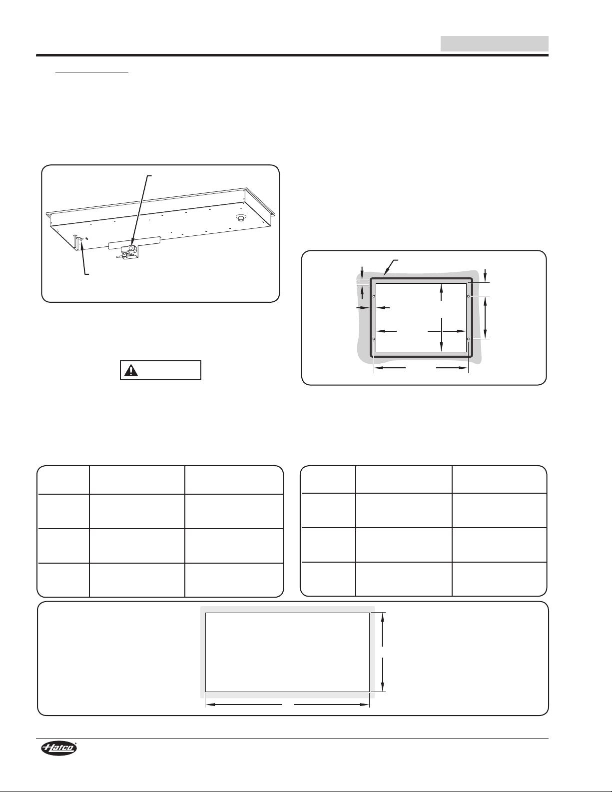
Locate the unit at the proper counter height in an area that is
convenient for use. The location should be level and strong
enough to support the weight of the unit and contents.
NOTICE
This unit is designed for use in environments where the
ambient temperature is between 65°F (18°C) and 86°F (30°C).
When shipped during cold weather months, store unit in
proper ambient temperature environment for 10 hours to
prevent compressor and/or refrigerant line damage. If unit
is turned on and there is excessive noise and vibration,
turn off immediately and allow additional warm up time.
Provide louvered or grill-style openings with a minimum
sizeof12″x12″/144squareinches(31x31cm/961square
cm) in the cabinetry in front of and behind the condensing
unit for proper ventilation. Failure to provide adequate air
flow through the condensing unit may cause unit failure
and will void the unit warranty.
Transport and install unit in upright position only. Failure
to do so may result in damage to the refrigeration system.
Use caution and avoid hitting condensing unit hoses/lines
when installing unit. Damage caused during installation is
not covered under warranty.
Do not locate unit in an area subject to excessive
temperatures or grease from grills, fryers, etc. Excessive
temperatures could cause damage to the unit.
Clean unit daily to avoid malfunctions and maintain
sanitary operation.
Use non-abrasive cleaners and cloths only. Abrasive cleaners
and cloths could scratch the finish of the unit, marring its
appearance and making it susceptible to soil accumulation.
Do not use steel wool for cleaning. Steel wool will scratch
the finish.
Do not use harsh chemicals such as bleach, cleaners
containing bleach, or oven cleaners to clean the unit.
This unit is intended for commercial use only—NOT for
household use.
Read the following important safety information before using this equipment to avoid serious
injury or death and to avoid damage to equipment or property.