Form No. NLXM-1213 3
IMPORTANT SA ETY IN ORMATION
English
EXPLOSION HAZARD: Do not store or use gasoline or
other flammable vapors or liquids in the vicinity of this or
any other appliance.
Make sure all operators have been instructed on the safe
and proper use of the unit.
This unit is not intended for use by children or persons
with reduced physical, sensory, or mental capabilities.
Ensure proper supervision of children and keep them away
from the unit.
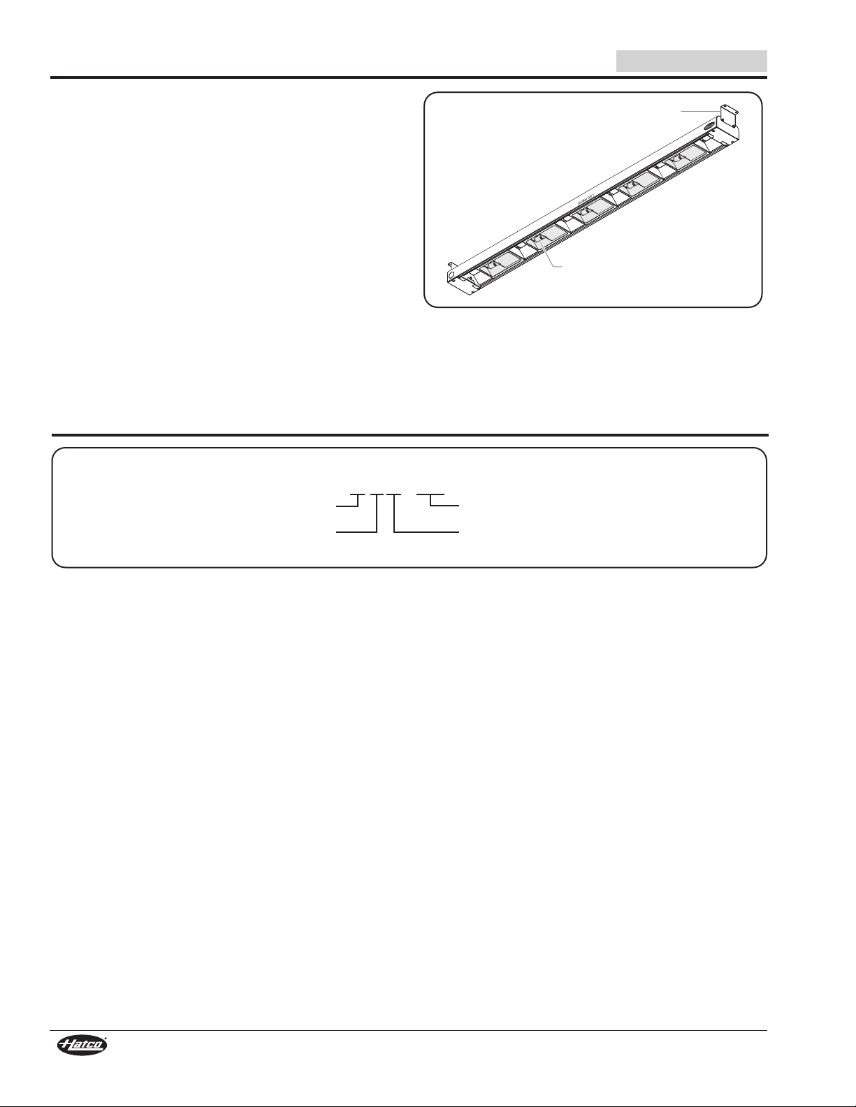
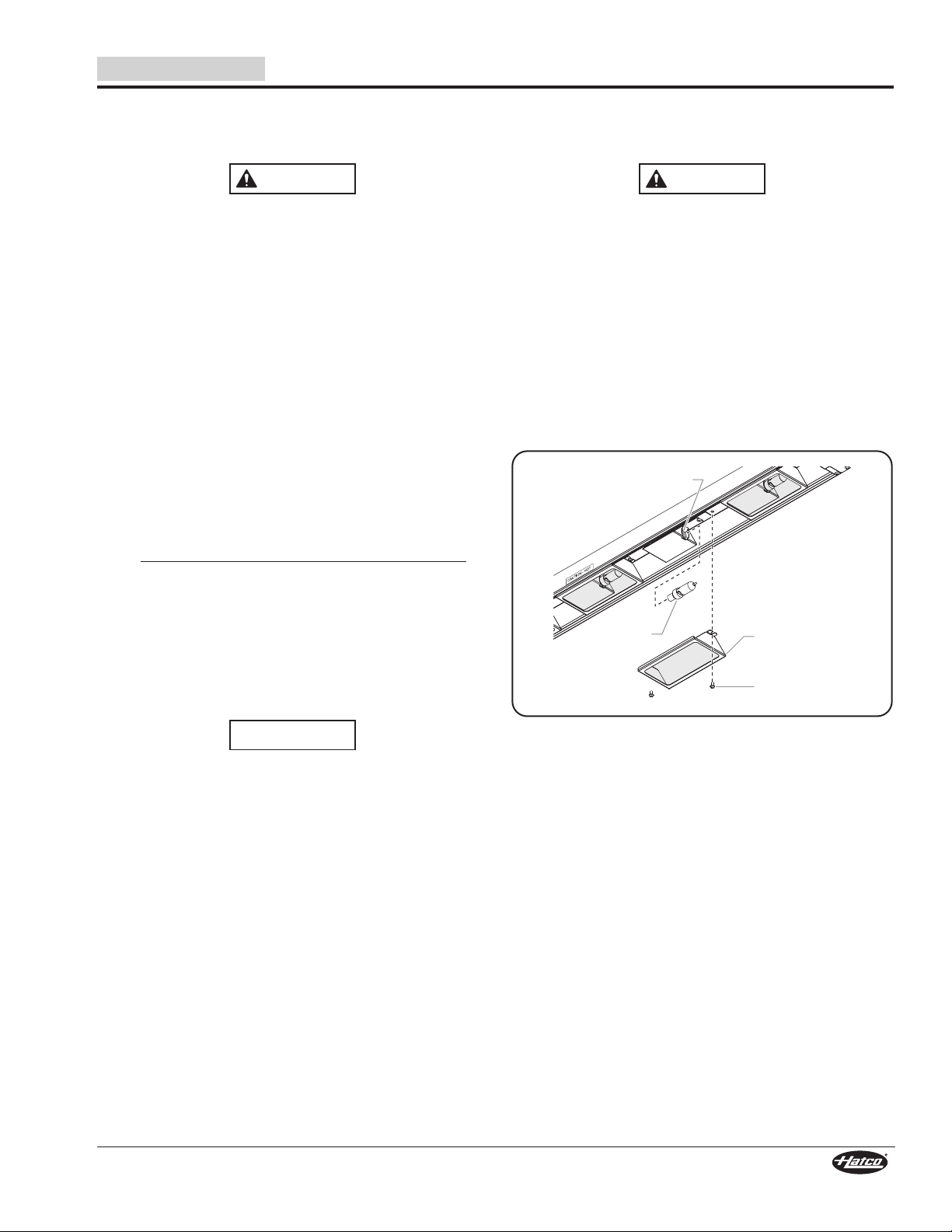
The light fixtures in this unit have glass safety shields
covering the light bulbs to meet National Sanitation
oundation (NS ) standards. To avoid personal injury
and/or food contamination, always operate the unit with
the glass safety shields properly installed.
Hatco Corporation is not responsible for actual food
product serving temperature. It is the responsibility of the
user to ensure that food product is held and served at a
safe temperature.
This unit has no “user-serviceable” parts. If service is
required on this unit, contact an Authorized Hatco Service
Agent or contact the Hatco Service Department at
800-558-0607 or 414-671-6350; fax 800-690-2966; or
International fax 414-671-3976.
Standard and approved manufacturing oils may smoke up
to 30 minutes during initial startup. This is a temporary
condition. Operate unit without food product until smoke
dissipates.
Ensure safe and proper operation. Refer to the “Installation
Site Requirements” listed in the INSTALLATION section of
this manual.
Use non-abrasive cleaners and cloths only. Abrasive
cleaners and cloths could scratch finish of unit, marring
its appearance and making it susceptible to soil
accumulation.
ELECTRIC SHOCK HAZARD:
• Unit must be installed by a qualified electrician.
Installation must conform to all local electrical codes.
Installation by unqualified personnel will void unit
warranty and may lead to electric shock or burn, as well
as damage to unit and/or its surroundings.
• Consult a licensed electrical contractor for proper
electrical installation conforming to local electrical
codes and the National Electrical Code (N.E.C.).
• When mounting above a steam table, each individual
well opening must not exceed 12"(30.5 mm) wide with
a maximum electrical rating of 2000 W per well.
• Turn O power at fused disconnect switch/circuit
breaker and allow unit to cool before performing any
cleaning, adjustments, or maintenance.
• DO NOT submerge or saturate with water. Unit is not
waterproof. Do not operate if unit has been submerged
or saturated with water.
• Do not clean unit when it is energized or hot.
• Unit is not weatherproof. Locate unit indoors where
ambient air temperature is a minimum of 70° (21°C).
• Do not steam clean or use excessive water on the unit.
• This unit is not “jet-proof” construction. Do not use jet-
clean spray to clean this unit.
• Control box must be mounted in a vertical surface.
Mounting control box in a horizontal surface may result
in the collection of liquids and lead to electric shock.
• This unit must be serviced by qualified personnel only.
Service by unqualified personnel may lead to electric
shock or burn.
• Use only Genuine Hatco Replacement Parts when
service is required. ailure to use Genuine Hatco
Replacement Parts will void all warranties and may
subject operators of the equipment to hazardous
electrical voltage, resulting in electrical shock or burn.
Genuine Hatco Replacement Parts are specified to
operate safely in the environments in which they are
used. Some aftermarket or generic replacement parts
do not have the characteristics that will allow them to
operate safely in Hatco equipment.
IRE HAZARD:
• Locate unit the correct distance from combustible walls
and materials. If safe distances are not maintained,
discoloration or combustion could occur. Refer to
specific installation and mounting information in this
manual for proper clearances.
• Make sure to follow the installation information listed
below for xenon display lights. If safe distances are not
maintained, discoloration or combustion could occur.
a. Do not install xenon display lights less than 10"
(254 mm) above combustible surfaces.
b. Do not install xenon display lights less than
7" (178 mm) above non-combustible surfaces.
c. Install all xenon display lights with a minimum
distance of 2" (51 mm) from any wall or adjacent
vertical surface.
Read the following important safety information before using this equipment to avoid
serious injury or death and to avoid damage to equipment or property.