Hatteland HD REM SX1-A1 User manual
1/2
This information may not, in whole or in part, be copied, photocopied,
reproduced, translated or reduced to any electronic medium or machine-
readable form without the prior written consent of Hatteland Technology
AS. The products may not be copied or duplicated in any way.
Dimensions might be shown with or without decimals and indicated as mm [inches]. Tolerance on drawings is +/- 1mm. For accurate measurements, check relevant DWG fi le.
DATASHEET
Hatteland Technology AS | www.hattelandtechnology.com | Enterprise no: NO974533146 1/6
The remote controller enables the control of Series 1 G2, Series X G1, Series X G2, MVD Series and selected HM CMD / RMD monitors
by providing instant keypad functionality over RS-485/422 bus through the well implemented SCOM Protocol by Hatteland Technology
AS. A single press on the remote controller will trigger the same physical press on all connected/configured units with the
synchronized reaction of corresponding button presses. The remote controller provides several functions through 3 physical buttons
for user interaction. Remote Control is powered and driven by first monitor unit (which has to be connected to external power cable/
source. It is not required to turn the monitor unit on for the Remote Control to control/operate other monitor units that may be in
the same chain).
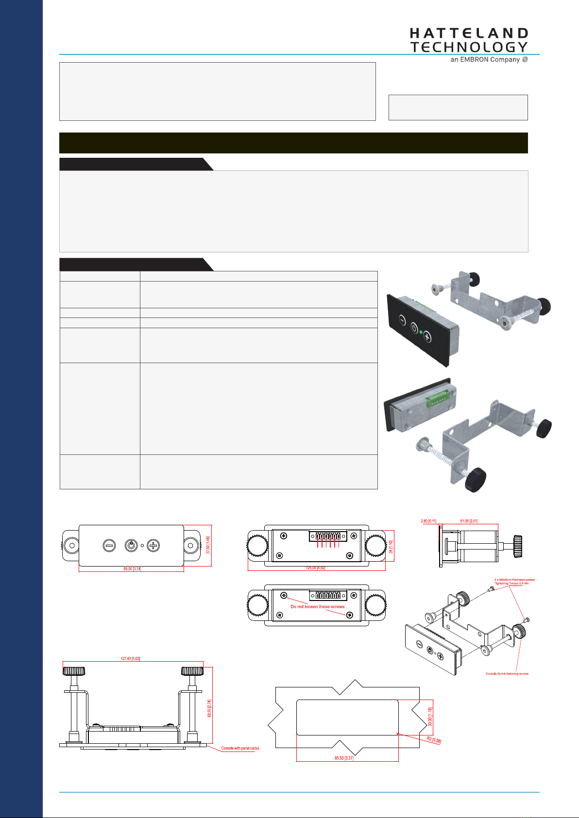
External Remote Controller for Monitors
Manufacturer: Hatteland Technology AS
Product: External Remote Controller for Monitors
Typenumber: HD REM SX1-A1
Last Revised: 16 Sep 2022
Revision#: 21
Description:
ACCESSORY
• Connector 1 x 6-pin Terminal Block 3.81, non-isolated
• Mounting Includes mounting bracket with 2 x PanHead M3x6mm.
(Tightening Torque 0.8 Nm) and 2 x Thumb Fastening screws for console
mounting.
• Physical Dimensions W:125.00 [4.92"] x H:37.50 [1.48"] x D:72.30 [2.83"] mm [inch]
• Weight 123g
• Connectivity - Shipped with 1 x 6-pin Terminal Block 3.81 loose connector (Art: 1828388)
- Connect Remote Control to rst display unit, other units in connection chain
will receive same commands.
- See page 2 for Physical Wire Connections.
• User Manual - This datasheet. Detailed usage: SCOM Technical Manual can be used with
command-set regarding User Controls:
Series 1 G2 models:
https://www.hattelandtechnology.com/hubfs/pdfget/inb100018-12.htm
Series X G1 models:
https://www.hattelandtechnology.com/hubfs/pdfget/inb100018-4.htm
Series X G2 models:
https://www.hattelandtechnology.com/hubfs/pdfget/inb100018-6.htm
Multi Vision Display MVD models:
https://www.hattelandtechnology.com/hubfs/pdfget/inb100018-8.htm
• Test and certicate Hatteland Technology standard, (tested / type approved by the
following classification societies):
IEC 60945 4th (EN 60945:2002), IACS E10,
EU RO MR - Mutual Recognition, ClassNK - Nippon Kaiji Kyokai
Specifications:
FRONT VIEW SIDE VIEW
BACK VIEW
TOP VIEW (w/ console panel)
PANEL CUTOUT
1 2 3 4 5 6

SPECIFICATIONS Note: All specifi cations are subject to change without prior notice!
Please visit www.hattelandtechnology.com for the latest electronic version.
2/2
2/6
Button layout and functions:
1 2 3
Status RGB LED
ID Visual Simulates Description Requires Physical Operation
1Decrease / Brightness Negative - In Normal Mode Press button and release
2Power Control, congured as ON / OFF In Normal Mode Press and hold down
button at least 3 seconds
3Increase / Brightness Positive + In Normal Mode Press button and release
1Arrow Left, congured as Navigation Back
or as Hot Key #1 In Menu Mode
2OSD Menu Access, congured as Show/Hide In Menu Mode
3Arrow Right, congured as Navigation Forward
or as Hot Key #2 In Menu Mode
-- Performs factory reset of the Remote Control In OFF Mode Press buttons and hold at
least 10 seconds
--Switches between Normal and Menu Mode as
default conguration on exiting from OFF mode In OFF Mode Press buttons and hold at
least 5 seconds
--Turns on or o Status RGB LED visibility as
default conguration on exiting from OFF mode In OFF Mode Press buttons and hold at
least 5 seconds
--Status RGB LED to indicate mode to user and
behaviour for the Remote Control None
The Remote Controller is designed to simulate the regular 6-button available on the Glass Display Control (GDC™)
as default available on all Series X products via a timer-based configuration explained as "Normal" and "Menu"
mode for the Remote Control, all these 6 buttons can be accessed and simulated at the same time, based on a
user intervention such as On-button-first-press (On Down), press-and-hold or just press-and-release on any of the
physical buttons.
1 2 3 1 3 2
Prior to using the Remote Control, the communication mode RS-485 (4-wire) must be congured and the monitor unit's RS adress must be set to "0". Two ways
are possible, either by OSD or by SCOM. Only the unit with address '0' allows OSD Menu control over remote controller. The units with other addresses do not
support OSD menu control. Normally, the address of each unit on the same bus, has to be unique.
Series X Generation 1 - HD xxT21 MMD
To get access, rst change menu mode:
1: OSD Settings > OSD Mode > Full > (Radio Button) and Enter Key Code “362”
2: Management Settings > Communication > 4-wire RS485/422 > (Radio Button)
3: Management Settings > Communication > Address RS > (Slider Bar)
Series X Generation 2 - HD xxT22 MMD
To get access, rst change from "Basic Mode" to "Advanced Mode":
1: OSD Miscellaneous > OSD Mode > Advanced > (Select) and Enter Key Code "362"
2: Management Settings > Communication > 4-wire RS485/422 > (Select)
3: Management Settings > Communication > Address RS > (Slider Bar 0~15)
Series X Generation 1 - HD xxT21 STD
To get access, rst change menu mode:
1: OSD Misc > OSD Mode > Full > (Radio Button) and Enter Key Code “362”
2: Management > Communication > 4-wire RS485/422 > (Radio Button)
3: Management > Communication > Address RS > (Slider Bar)
Multi Vision Display / MIL - HD xxT22 MVD / HM xxT22 RMD,HM xxT22 CMD:
To get access, rst change from "Basic Mode" to "Advanced Mode":
1: OSD Menu > OSD Mode > Advanced> (Select) and Enter Key Code “362”
2: Communication > 4-wire RS485/422 > (Automatic Action)
3: Communication > Address RS > (Slider Bar)
Via SCOM Command (applicable for all units / product ranges above):
Send Bytes (shown here as HEX, 30= value "0"): 07 FF 4D 43 43 02 24 BB 30 14
Configuration of monitor unit:

SPECIFICATIONS Note: All specifi cations are subject to change without prior notice!
Please visit www.hattelandtechnology.com for the latest electronic version.
2/2
3/6
Remote Control schematic logic:
Remote Control has several states of which its logic is interpreted. These modes are identied as Start, OFF mode, Initalization Mode, Normal Mode and Menu
Mode. Diagram below is only for illustration.
Initialization mode:
The Status RGB LED will be lit in yellow and enter
"Normal Mode". This status only occurs when the
Remote Control is powered ON or enters from previous
OFF mode. This mode is not programmable by user.
OFF mode:
OFF
mode
Initialization
mode
Normal
mode
Menu
mode
Start
The Status RGB LED will be lit in red, green, yellow or be o (black) depending on logic detected as
illustrated below. This mode is dependent on conguration, key presses and responses. Responses
can be either internal logic or by user intervention such as On-button-rst-press (On Down),
press-and-held or just press-and-release on any of the physical buttons within the milliseconds
indicated below.
- On Down : action on button press down
- Hold : button is pressed down and hold in this position
- Click : button was pressed down and released
SPECIFICATIONS Note: All specifi cations are subject to change without prior notice!
Please visit www.hattelandtechnology.com for the latest electronic version.
2/2
4/6
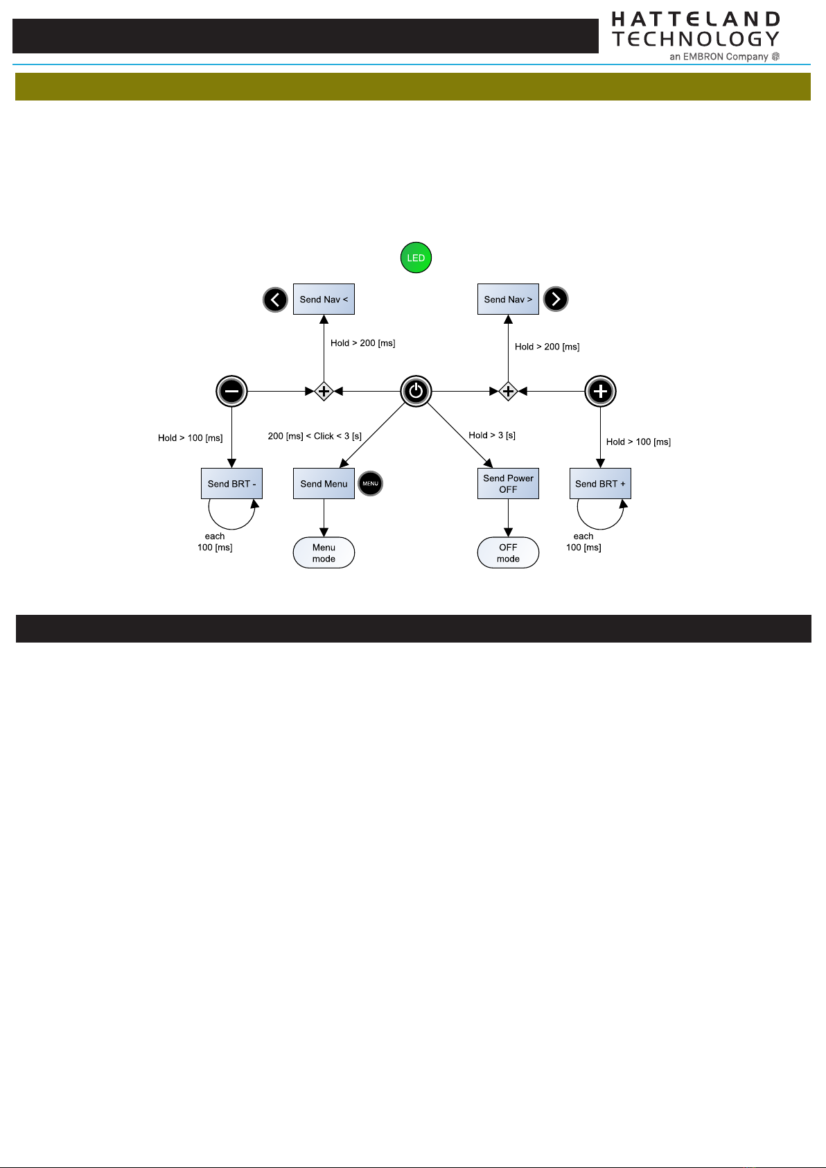
Normal mode:
The Status RGB LED will be lit in green depending on logic detected as illustrated below. This mode is dependent on conguration, key presses and responses.
Responses can be either internal logic or by user intervention such as On-button-rst-press (On Down), press-and-hold or just press-and-release on any of the
physical buttons within the milliseconds indicated below.
- On Down : action on button press down
- Hold : button is pressed down and held in this position
- Click : button was pressed down and released
Step-by-Step to test mode
TBD - PENDING Q4-2022
SPECIFICATIONS Note: All specifi cations are subject to change without prior notice!
Please visit www.hattelandtechnology.com for the latest electronic version.
2/2
5/6
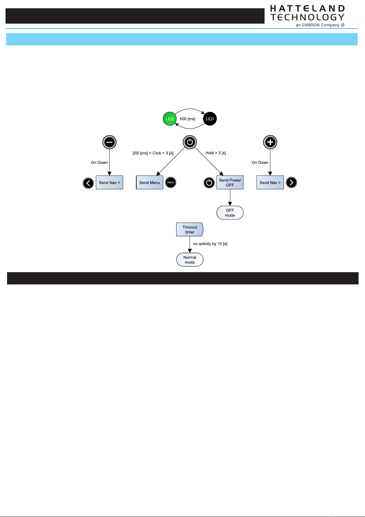
The Status RGB LED will be lit in green or be o (black) depending on logic detected as illustrated below. This mode is dependent on conguration, key presses
and responses. Responses can be either internal logic or by user intervention such as On-button-rst-press (On Down), press-and-hold or just press-and-release
on any of the physical buttons within the milliseconds indicated below.
- On Down : action on button press down
- Hold : button is pressed down and held in this position
- Click : button was pressed down and released
Menu mode:
Step-by-Step to test mode
TBD - PENDING Q4-2022
SPECIFICATIONS Note: All specifi cations are subject to change without prior notice!
Please visit www.hattelandtechnology.com for the latest electronic version.
2/2
6/6
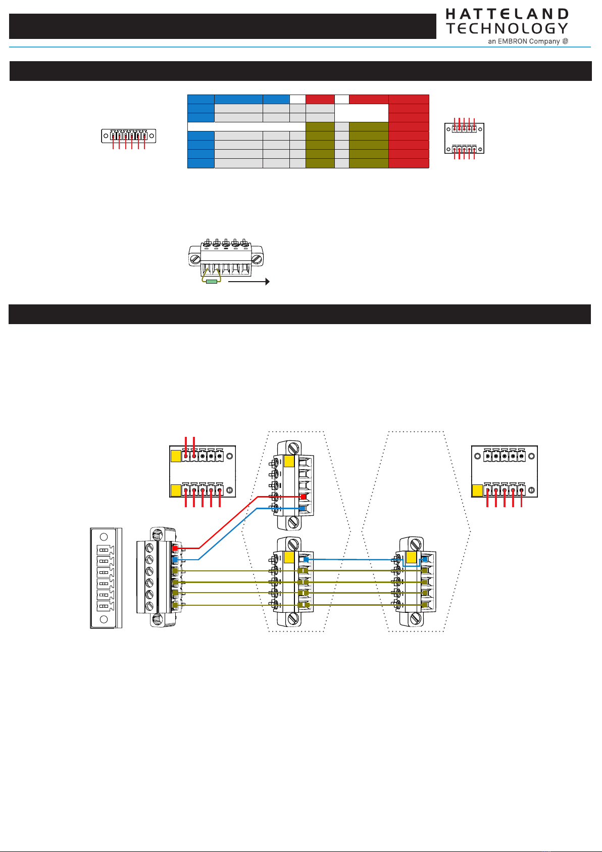
Info Remote Side Info to Unit #1 to Unit #2-16 Info
+5V In PIN 01 +5V In →PIN 04 +5V Out
GND PIN 02 GND →PIN 02 GND
PIN 09 →PIN 09 GND100Ω
RxD- PIN 03 RxD- →PIN 07 →PIN 07 TxD-
RxD+ PIN 04 RxD+ →PIN 05 →PIN 05 TxD+
TxD- PIN 05 TxD- →PIN 03 →PIN 03 RxD-
TxD+ PIN 06 TxD+ →PIN 01 →PIN 01 RxD+
1 2 3 4 5 6
On Remote Control:
To chain more than 1 single unit, 5 pins/cables are needed onward (marked in table above with brown).
+5V is only needed to power Remote Control from first/master unit.
Note: Remote Controller should be the only master device on RS-485 / RS-422 bus.Message sent from other device will be ignored.
On Unit(s):
2 4 6 8 10
1 3 5 7 9
Optionally, a 120Ω resistor is recommended between
PIN 1 (RxD+) and PIN 3 (RxD-) for longer cables on the last unit in chain.
1 3 5 7 9
Pinout assignments and electrical details:
6-pin T.Block Connector
for Remote Control.
2 x 5-pin T.Block Connector
(MC 1,5/ 5-STF-3,81)
on 1st Unit needed.
1 x 5-pin T.Block Connector
(MC 1,5/ 5-STF-3,81)
for units 2 upto 16 in chain.
1st Unit
(Must be powered). Unit 2 up to 16
1 2 3 4 5 6
2 4
1 3 5 7 9
1 3 5 7 9
Physical wire connections:
Use loose Terminal Block Connectors from Package of Contents that followed the monitor unit and the HD REM SX1-A1 Remote Control. Cables and Cable length
must be provided by customer. Recommended Cable Thickness: Minimum 22 AWG - Maximum 18 AWG. Creation/cabelling illustrates a 2 unit setup.
Max 16 units in chain is possible to control with Remote Control.
1 2 3 4 5 6
2 4
1 3 5 7 9
1st Unit Pinout
Remote control
Pinout 1 3 5 7 9
Unit 2 up to 16,
Pinout
1
2
1
2
3
3
Table of contents


