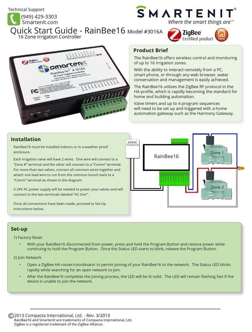
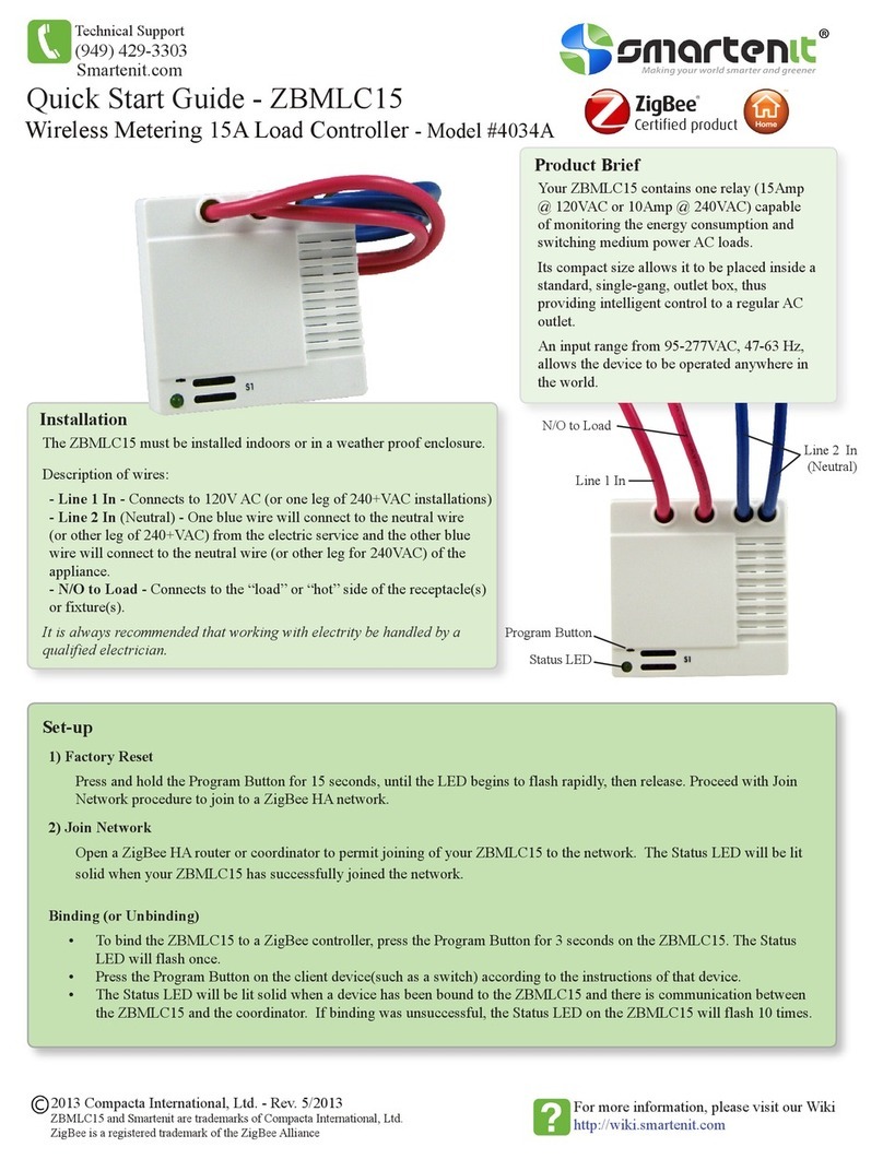
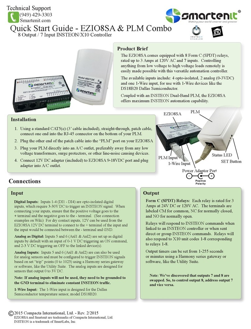
Smartenit EZIO2X4 5010D User manual

Quick-Start Guide EZIO2X4—Model #5010D—2-Relay/4-Input Controller
Your EZIO2X4 puts control of loads and monitoring of signals where needed, avoiding wiring complications. The unit has 2 relays to control
small, DC or AC loads with INSTEON or X10 commands. Relays can be linked simultaneously or individually to a controller such as a
KeypadLinc or ControlLinc and timers can be set up to pulse each relay from 1 second to 255 minutes. External signals such as contact closures or
analog sensors (0—5VDC) can trigger group commands on their opening, closing or changing levels to cause INSTEON events. Response of the 4
inputs is programmable with the help of a free Windows-XP utility or home automation software. Two of the inputs are opto-isolated plus two are,
in addition to digital inputs, configurable for analog signals from items such as environmental sensors (light, temperature, pressure, humidity, etc.)
EZIO2X4 has a built-in power line interface and is programmed/controlled through the power line. INSTEON and X10 compatibility means
virtually unlimited connectivity, including wireless networks and the Internet.
Installation
• Select a suitable power outlet that is close to the loads and sensors to be connected. Avoid exposure to
moisture. If installing outdoors, use only an approved outdoor weather-proof enclosure.
• Connection of the Output Relays: Follow the pic-
ture on the label and note the nomenclature (Rx_A
and Rx_B) on the detachable terminal barrier con-
nector (shown above) for relays 1 and 2. Note that
each relay acts as a switch (rated .5A at 30VDC or
120VAC.) Connect the controlled loads (e.g. valve motors, curtain actuators, door lock solenoids, gar-
age door switches, etc.) to each pair of relay terminals (i.e. load 1 between R1_A and R1B, and load 2
between R2_A and R2_B). Each relay is individually controlled by either direct or group INSTEON
messages, or by X10 commands. A subsequent section of this guide describes how to link an INSTEON
sender or X10 controller to each output. Using INSTEON, it is also possible to take a “snapshot” of the
state of the outputs for single command “recollection” of the snapshot as part of a scene.
• Connecting the Inputs: Two sets of inputs to your EZIO2X4 are available through the same terminal
connector pictured above and described separately below. Notice also that separate terminals are provid-
ed for +5VDC (20 mA. maximum) and Ground.
• Opto-Isolated Inputs: Inputs I1 and I2 can be used in a way that the signal source is totally isolated
from the EZIO2X4, as may be the requirement for certain alarm panel monitoring. In this case, the input
must provide a voltage between 3 and 30 VDC, connected between the positive (I1+ or I2+) and negative
(I1– or I2-) terminals. If isolation is not required, these inputs can easily be connected to “dry” contact
closures such as those from external relays, proximity detectors or door closure sensors. In this case,
connect the positive (I1+ or I2+) terminal to the +5V terminal, and the contact closure between the nega-
tive (I1- or I2-) terminal and the GND terminal.
• I3 and I4 as Digital Inputs: As configured by default, inputs I3 and I4 can be used to monitor voltage
levels that have distinct thresholds (0—1VDC for ON, and 3—5VDC for OFF.) These are the levels
typically produced by digital devices such as a control output from a liquid level detector or telephone
answering device. Keep in mind that the device output can not be of the “dry” type; in other words, the
output connecting to the EZIO2X4 I3 or I4 inputs must provide a voltage level required to cause a
change that the EZIO2X4 can recognize. If needed, a “pull-up” resistor can be connected between the
particular input (I3 or I4) and the +5VDC terminal. In this case, do not exceed the maximum 20mA
current rating of this terminal.
• I3 and I4 as Analog Inputs: A software program such as our free utility or a home automation program
may be used to configure I3 and I4 as inputs that respond to and measure the level of voltages between 0
and 5VDC. Typical uses for this type of monitoring could be light, temperature, pressure, humidity, or
other slowly and discretely varying levels. The value of the voltage at each of the inputs is internally
converted to a number between 0 and 1023 (10 bits) which can be read via INSTEON commands or
used to trigger alarm conditions. Alarms are simply events when the EZIO2X4 sends a group mes-
sage to the INSTEON network. Using this facility, an alarm can be set to send an INSTEON OFF
group command when the voltage on the given input goes over a certain level, and an INSTEON ON
group command when the voltage falls below a different level. This allows many possibilities for
closed-loop control such as for maintaining the level of a pool, the temperature in a room, the humidi-
ty in a greenhouse, etc.
• Plug your EZIO2X4 into an AC outlet. The LED on its side may flash on and off rapidly a few times,
then turn on and off for about 1 second (indicating successful internal diagnostics), and finally glow
steadily.
Programming Your EZIO2X4
EZIO2X4 can be set up as a “Sender” that sends INSTEON group commands or broadcast messages
upon changes on any of its inputs (OFF to ON or ON to OFF), or as a “Responder” that activates one or
both of its relays in response to a command from a controller such as a KeypadLinc or ControlLinc. The
relays on the EZIO2X4 can also be controlled with INSTEON direct commands.
The many features of the EZIO2X4 are best exploited with an automation PC/Server application or our
free Windows-XP configuration and setup utility. The PC application can be used to alter the behavior
of the inputs, such as, what command is sent on the detection of an OFF or ON condition, the IN-
STEON group number, a timer to delay the input OFF response, and/or the alarms on the Analog inputs.
The unit is usable out-of-the-box manually as described below. Please note that a “Press and Hold”
refers to pushing and holding, then releasing the set-button on the side of the EZIO2X4. A “Tap” refers
to gently and rapidly depressing and releasing the button.
Controlling One or Multiple INSTEON Devices with Signals on the Inputs
1) Put the EZIO2X4 in linking mode by pressing its pushbutton and releasing it after 10-12 seconds.
The EZIO2X4 will turn off its LED indicating it is waiting to be told which input is to be used for this
link.
2) Tap the pushbutton on the EZIO2X4 a number of times corresponding to the input to be used for
control (e.g. once for input 1, twice for input 2, etc.) After the last tap, press the pushbutton on the
EZIO2X4 and release it after 3-4 seconds. Its LED will begin to flash about once per second indicat-
ing it is listening for an INSTEON device to link with.
3) On the INSTEON device to be controlled, press its pushbutton and release it after 3-4 seconds (or use
method specific to device.) A successful link will be indicated by a flash of the LED on the con-
trolled device (device specific) and by the LED on the EZIO2X4 flashing, then continuing to blink
about once per second indicating readiness to link another device.
1-949-429-3303 Smartenit.com © 2006 Compacta International, Ltd.
INSTEONis a trademark of SmartLabs, Inc. and the INSTEON networking technology is covered by pending U.S. and foreignpatents.
Version 2.0 1/2/08 Page 1 of 2
Applies to firmware 2.2 and above
Set-Button
and LED
Connection to
Inputs and Relays

4) Continue to link additional INSTEON devices using step 3 above, or end the linking session by holding
the pushbutton on the EZIO2X4 for 3-4 seconds.
Stopping (Unlinking) an INSTEON Responder Device from being controlled by the EZIO2X4
1) Put the EZIO2X4 in unlinking mode by pressing its pushbutton and releasing it after 10-12 seconds. The
EZIO2X4 will turn off its LED indicating it is waiting to be told which input the INSTEON device is to
be unlinked from.
2) Tap the pushbutton on the EZIO2X4 a number of times corresponding to the input to be unlinked (e.g.
once for input 1, twice for input 2, etc.) After the last tap, press the pushbutton on the EZIO2X4 and
release it after 18-20 seconds. Its LED will begin to flash about once per second indicating it is listening
for an INSTEON device to unlink from.
3) On the INSTEON device to be unlinked, press its pushbutton and release it after 3-4 seconds (or use
method specific to device.) A successful unlink will be indicated by a flash of the LED on the controlled
device (device specific) and by the LED on the EZIO2X4 turning on solidly.
Triggering EZIO2X4 Inputs from another INSTEON Controller
1) Put controller in linking mode by holding the button to be used for controlling until it indicates linking
mode (4-10 seconds depending on controller.) Usually its LED will blink or a light connected to it will
flash.
2) Hold the pushbutton on the EZIO2X4 and release it after 3-4 seconds. The LED on the EZIO2X4 will
turn off when the link is established with the controller. The controller will also give an indication of a
successful link by flashing its LED or a load connected to it.
3) The EZIO2X4 must be told which input to link by tapping the pushbutton on the EZIO2X4 a number of
times corresponding to the input number (e.g. once for input 1, twice for input 2, etc.) After the last tap,
press the pushbutton on the EZIO2X4 and release it after 10-12 seconds. Its LED will turn on solidly
indicating the end of the linking process.
Controlling the Relays with an INSTEON Controller
1) Put controller in linking mode by holding the button to be used for controlling until it indicates linking
mode (4-10 seconds depending on controller.) Usually its LED will blink or a light connected to it will
flash.
2) Hold the pushbutton on the EZIO2X4 and release it after 3-4 seconds. The LED on the EZIO2X4 will
turn off when the link is established with the controller. The controller will also give an indication of a
successful link by flashing its LED or a load connected to it.
3) To link the current status of all the relays (status snapshot) to be recalled by a command from the con-
troller, hold the pushbutton on the EZIO2X4 and release it after 3-4 seconds. The LED on the
EZIO2X4 will turn on solidly indicating the end of the linking process.
4) Alternatively to step 3 above, an individual relay is linked by tapping the pushbutton on the EZIO2X4 a
number of times corresponding to the relay number (e.g. once for relay 1, twice for relay 2, etc.) After
the last tap, press the pushbutton on the EZIO2X4 and release it after 3-4 seconds. Its LED will turn on
solidly indicating the end of the linking process.
Unlinking the Relays from an INSTEON Controller
1) Follow the instructions specific to the INSTEON controller in use to place it in unlinking mode.
2) On the EZIO2X4, press its pushbutton and release it after 3-4 seconds. Its LED will flash briefly and
then go solid indicating a successful unlink. The LED on the controller will also go solid.
About the Links Database
The EZIO2X4 maintains an internal table of up to 30 links where the information on each linked device is
stored. The database can be accessed and altered with the use of our PC utility such that links can be en-
tered, modified or deleted without having to use the “press and hold” method described earlier.
Controlling the Relays with X10 Controllers
Although only four X10 units are used, EZIO2X4 allocates all 16 units of a house code. Relays 1 and 2
respond to commands on X10 units 1 and 2. To setup the unit to respond to X10 commands follow
these steps:
1) Press and hold the set-button and release it after about 4 seconds—the LED will now blink at a low
rate;
2) Enter an ON (or OFF for disabling) command from your X10 controller—the LED will stop flashing
indicating X10 enabling or disabling was successful. The outputs will now respond to X10 ON and
OFF commands.
To disable X10 control, substitute an OFF command in step 2 above.
Restoring All Parameters to Default (Factory Reset)
To restore all settings to their original factory values, unplug your EZIO8T for about 10 seconds. Then,
plug it back in WHILE HOLDING THE PUSH BUTTON for about 10 seconds. Upon release of the
push button, the unit will go through the normal power on sequence, and all parameters will be reset.
Example Application: Complete Garage Manager
In this example the EZIO2X4 is used to monitor the state of a garage door (open or closed) and to con-
trol the manual switch that activates the door opener. EZIO2X4 is set up to send an INSTEON ON
group command to a set of devices when the door is open, and an OFF command some minutes later.
The door open detection can also be programmed to send a command to close the door through one of
the EZIO2X4 relays some minutes later if the door is detected to be open. A readily available magneti-
cally activated sensor (reed switch type) is used as a door open/close sensor. This switch simply closes
when next to a magnet, and opens when away from the magnet. Our setup PC utility is used to config-
ure the links, the response of the inputs and the relay timer. Simply follow the steps below:
1. The picture on the right shows a typical magnetically activated sensor/
switch. Some may come with wires already terminated, and others, as the
one pictured, come with screw terminals. Connect I1+ to the +5V terminal
and I1– to one wire of the door sensor. Connect the other sensor wire to the
GND terminal.
2. Connect the two wires from the opener pushbutton to the R1_A and R1_B
terminals on the EZIO2X4.
3. Link INSTEON devices to respond to door open or close events by following the steps in the section
“Controlling One or Multiple INSTEON Devices with Signals on the Inputs”. It is possible to
link one or several INSTEON devices (lights, sirens, telephone dialers, etc.) that will be given com-
mands when the door opens or closes.
4. If needed, use the set up utility to set the ON to OFF (door opening) and/or OFF to ON (door clos-
ing) commands to be sent. INSTEON commands are 13 00 for “Rapid OFF” and 11 FF for “Rapid
ON”.
5. Programming Relay 1 to Activate the Door Opener Switch: Use the setup utility to a) set the
output timers in seconds; b) program the output 1 timer to 2 seconds; and c) establish a link to have
output 1 respond to group 1.
1-949-429-3303 www.smartenit.com © 2006 Compacta International, Ltd.
INSTEONis a trademark of SmartLabs, Inc. and the INSTEON networking technology is covered by pending U.S. and foreignpatents.
Version 2.0 1/2/08 Page 2 of 2
Applies to firmware 2.2 and above
Monitor and Control Anything from Anywhere! View smart solutions for energy management
and home/building controls at http://video.smartenit.com
Other Smartenit Controllers manuals
Popular Controllers manuals by other brands
DOREMIDI
DOREMIDI MIDI light box instructions
Unitronics
Unitronics Vision 230 installation guide
REGULA
REGULA medius 600 SR Installation and operating instructions
ROBBE
ROBBE RO-CONTROL PRO WIFI 2-6S 80 A HV-BEC user manual

Arrakis Systems
Arrakis Systems H Series Technical manual
Uniteck
Uniteck UNIMPPT 80.15/24 instruction manual
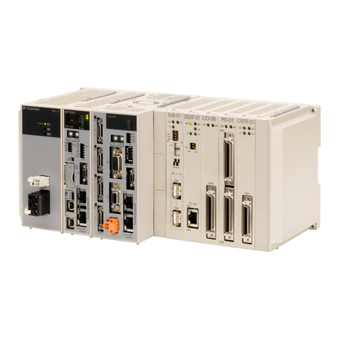
YASKAWA
YASKAWA JEPMC-PSA3012-E user manual

Heatcraft Refrigeration Products
Heatcraft Refrigeration Products H-IM-79D Installation & operation manual
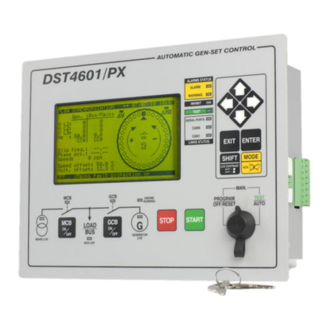
Sices
Sices DST4601/PX user manual
Datalogic
Datalogic HF-CNTL-IND-02 installation guide

oventrop
oventrop REGTRONIC PX Instructions for installers
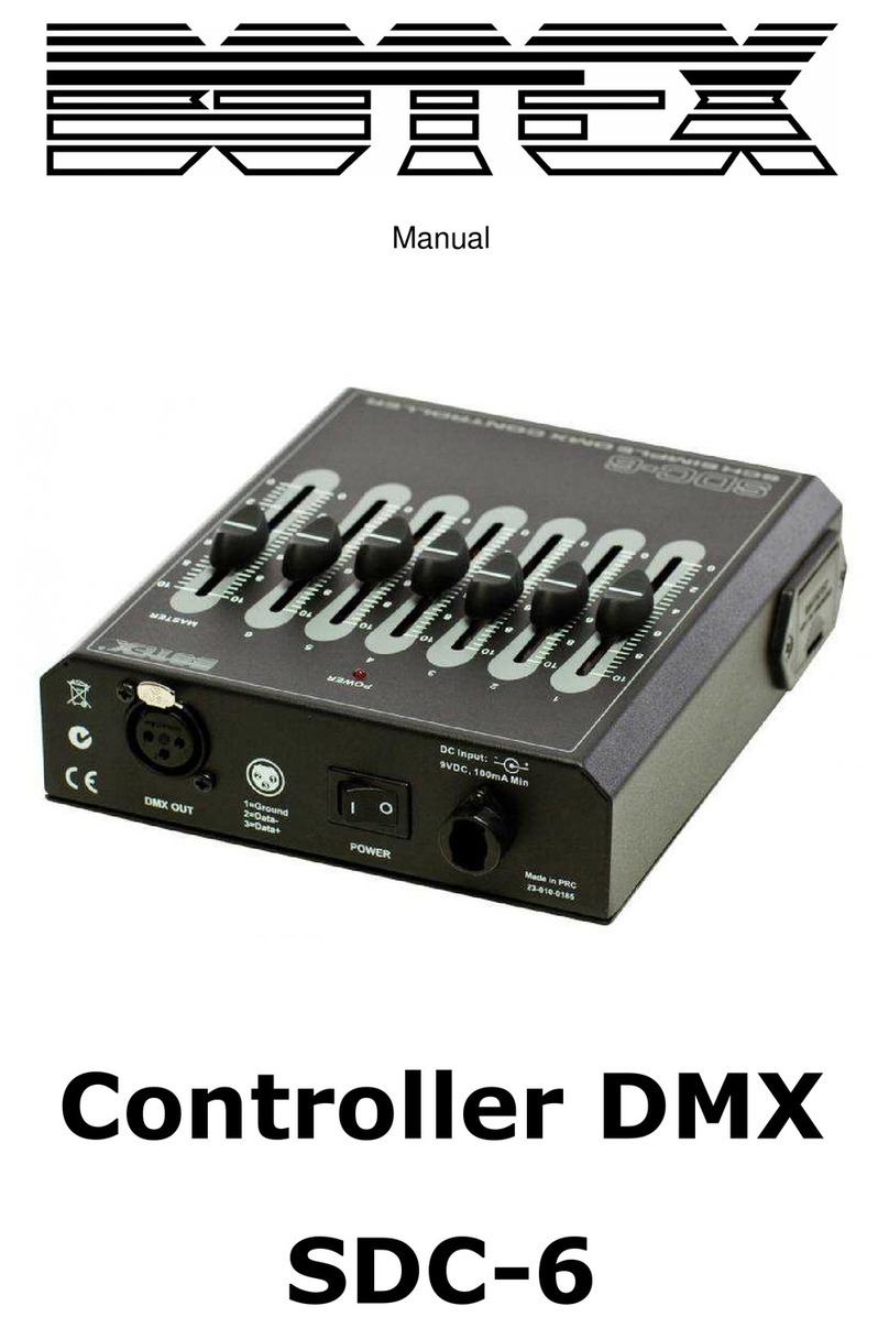
Botex
Botex SDC-6 manual
