Hatz 1B30V User manual

INSTRUCTION BOOK
33
1B 30V
1B 40V
1B 40W
1B 50V
1B 50W
433 816 76-USA-EPA IV-CARB
12.07-0.05
Printed in Germany
INCLUDES SUPPLEMENTAL INFORMATION TO THE
OWNER’S MANUAL FOR 2008 AND LATER EPA CERTIFIED
NONROAD COMPRESSION-IGNITION ENGINES
INCLUDES SUPPLEMENTAL INFORMATION TO THE
OWNER’S MANUAL FOR 2008 AND LATER CALIFORNIA
REGULATIONS FOR HEAVY-DUTY OFF-ROAD ENGINES

A new HATZ Diesel engine - working for you
This engine is intended only for the purpose determined and tested by the manufacturer of the
equipment in which it is installed. Using it in any other manner contravenes the intended purpose.
For danger and damage due to this, Motorenfabrik HATZ assumes no liability. The risk is with the
user only.
Use of this engine in the intended manner presupposes compliance with the maintenance and repair
instructions laid down for it. Noncompliance leads to engine breakdown.
Please do not fail to read this operating manual before starting the engine. This will help you to avoid
accidents, ensure that you operate the engine correctly and assist you in complying with the mainte-
nance intervals in order to ensure long-lasting, reliable performance.
Please follow all maintenance references carefully including the schedule for 2008 and later
EPA certified nonroad compression-ignition engines and for 2008 and later CARB certified
off-road engines to prevent our environment.
Please pass this Instruction Manual on to the next user or to the following engine owner.
The worldwide HATZ Service Network is at your disposal to advise you, supply with spare parts and
undertake servicing work.
You will find the address of your nearest HATZ service station in the enclosed list.
Use only original spare parts from HATZ. Only these parts guarantee a perfect dimensional stability
and quality. The order numbers can be found in the enclosed spare parts list. Please note the spare
part kits shown in Table M00.
We reserve the right to make modifications in the course of technical progress.
MOTORENFABRIK HATZ GMBH & CO KG
1

Page
1. Important safety notes
when operating the engine 3
2. Description of the engine 5
3. General notes 6
3.1. Technical data 6
3.2. Transport 7
3.3. Notes on installation 7
3.4. Load on engine 7
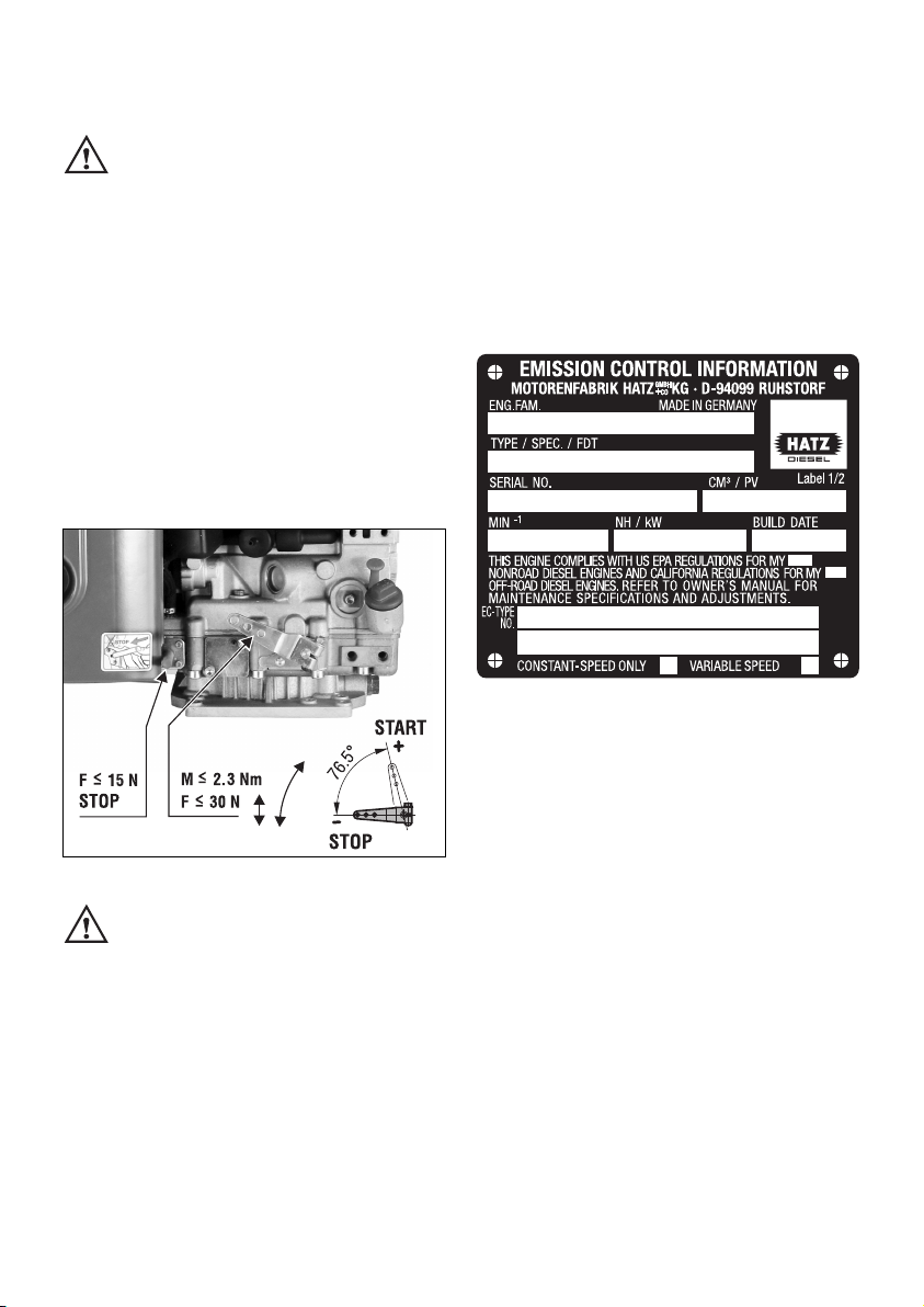
3.5. EPA / CARB - type plates 7
3.6. Emission-related installation
instructions 9
3.7. Closed crankcase ventilation system 9
4. Operation 9
4.1. Prior to first-time start-up 9
4.1.1. Engine oil 9
4.1.2. Fuel 10
4.2. Starting 11
4.2.1. Preparations for starting 11
4.2.2. Recoil start for versions without
electric starter 11
4.2.3. Recoil start for versions with
electric starter 12
4.2.4. Electric starter 13
4.3. Stopping the engine 15
5. Maintenance 17
5.1. Maintenance chart 17
5.2. Maintenance every 8 – 15
operating hours 19
5.2.1. Checking engine oil level 19
5.2.2. Check air intake area for
combustion and cooling 19
5.2.3. Check air cleaner maintenance
indicator 19
Page
5.3. Maintenance every 250
operating hours 20
5.3.1. Changing engine oil 20
5.3.2. Checking and adjusting
valve clearances 20
5.3.3. Cleaning the air cleaner zone 22
5.3.4. Checking screw connections 22
5.3.5. Cleaning the exhaust mesh inlet 22
5.4. Maintenance every 500
operating hours 23
5.4.1. Renewing fuel filter 23
5.4.2. Air cleaner maintenance 24
5.5. Maintenance every 1000
operating hours 26
5.5.1. Cleaning the oil filter 26
5.6. Servicing: once a year 27
5.6.1. Draining the fuel tank 27
6. Malfunctions – causes – remedies 29
7. Work on the electrical system 33
8. Storage out of use 33
SUPPLEMENTAL INFORMATION TO
THE OWNER’S MANUAL FOR 2008
AND LATER EPA CERTIFIED NONROAD
COMPRESSION IGNITION ENGINES 35
SUPPLEMENTAL INFORMATION
TO THE OWNER’S MANUAL FOR
2008 AND LATER CALIFORNIA
REGULATIONS FOR HEAVY-DUTY
OFF-ROAD ENGINES 45
2
Contents
This symbol identifies important safety precautions.
Please comply with these most carefully in order to avoid any risk of injury to persons or
damage to materials.
General legal requirements and safety regulations issued by the competent authorities or
industrial accident insurers must also be complied with.

1. Important safety notes when operating the engine
HATZ diesel engines are efficient, strong and durable. For this reason they are frequently installed on
equipment used for commercial purposes.
The manufacturers of such equipment must observe any relevant equipment safety regulations when
the engine forms part of an overall system.
A few general points concerning operating safety should none the less be noted.
Depending on the engine’s operating and installation conditions, equipment manufacturers and their
users may have to fit safety or protective devices in order to prevent improper use. Examples:
– Exhaust system components as well as the surface of the engine will naturally be hot and must not
be touched while the engine is running or until it has cooled down after being stopped.
– Incorrect wiring or improper operation of the electrical system may cause sparking and must there-
fore be avoided.
– Provide protection against contact with rotating parts once the engine is connected to the driven
equipment or machine.
HATZ protective guards are available for the belt drive of the cooling fan and alternator drive
systems.
– Always observe the start-up information in the operating instructions before starting the engine:
this is particularly important when starting an engine with the recoil starter !
– Mechanical starting devices should not be operated by children or persons deficient in physical
strength.
– Check that all safety devices are in place before starting the engine.
– Ensure that operation, maintenance and repair of the engine are undertaken by suitably trained
personnel only.
– Protect the starter key against unauthorised use.
– Do not run the engine in closed or badly ventilated rooms.
Do not breath in emissions – danger of poisoning!
– Also fuel and lubricants could contain poisonous components. Please follow the instructions of the
mineral oil producer.
3

Important safety notes when operating the engine
– The engine must be stopped before performing any maintenance, cleaning- or repair work.
– Stop the engine before refilling the fuel tank.
Never refuel near a naked flame or sparks which could start a fire. Don’t smoke. Don’t spill fuel.
– Keep explosive materials as well as flammable materials away from the engine because the exhaust
gets very hot during operation.
– Wear close-fitting clothing when working on the engine while it is running.
Please don’t wear necklaces, bracelets or any other things which you could get caught with.
– Please pay attention to all advice- and warning stickers placed on the engine and keep them in
legible condition. Contact your next HATZ service station, if a sticker comes off or is illegible and
ask for a new one.
– We accept no liability for damage resulting from improper modifications to the engine.
Regular servicing in accordance with the details provided in this Instruction Book is essential to keep
the operating reliably and to ensure the exhaust quality of the engine.
When in doubt, consult your local HATZ service station before starting the engine.
4

2. Description of the engine
5
Fig 1
1 Fuel tank cap
2 Recoil starter
3 Dry-type air cleaner
4 Intake opening for cooling and
combustion air
5 Voltage regulator
6 Starter motor
7 Noise insulating hood
8 Lifting lug
9 Engine shutdown pin
10 Speed control lever
11 Oil filler pipe
12 Oil filter
13 Oil drain plug
14 Dipstick
15 Exhaust mesh insert
16 Exhaust silencer
17 Type plate

3. General notes
3.1. Technical data
1) These values are intended as an approximate guide. The max. marking on the dipstick is the
determining factor, Fig. 7.
2) Depending on model (see maintenance charts, chapter 5.1)
3) Exceeding these limits causes engine breakdown.
Tightening torques
Item Nm
Oil drain plug 50
Type 1B30 V 1B40 V/ W 1B50 V/ W
Design Air-cooled four-stroke diesel engine
Combustion system Direct injection
Number of cylinders 1 1 1
Bore / stroke mm 80 / 69 88 / 76 93 / 76
Displacement cm3347 462 517
Lubricating oil capacity l, approx. 1.1 1) 1.5 1) 1.5 1)
Difference between
„max.“ and „min“ levels l, approx. 0.5 1) 0.8 1) 0.8 1)
Lubricating oil consumption
after a running-in period max. 1 % of fuel consumption at full load
Lubricating oil pressure
(oil temperature 100 °C) approx. 2.5 bar at 3000 r.p.m.
Direction of rotation,
power take-off end counterclockwise
Valve clearance 10 - 30 °C
Inlet and exhaust valve mm 0.10 0.10 0.10
or automatically 2)
Max. angle from vertical in any
direction (continuous operation) 25° 3)
Weight (incl. fuel tank, air-cleaner,
exhaust silencer, recoil starter and
electric starter)
kg
approx. 42
1B40 V : 55
1B40 W: 57
1B50 V : 56
1B50 W: 58
Battery capacity max. 12 V / 60 Amp/h
6

3.2. Transport
Standard lifting lug „8“ is to allow the
engine and its auxiliaries to be trans-
ported safely, chap. 2. It is not suitable or ap-
proved for lifting the complete equipment to
which the engine is attached.
3.3. Notes on installation
The „Guide to selecting and installing an engine“
contains all the necessary information on engine
applications if you have an engine which has not
yet been installed in equipment and still has to
be fitted or set up.
This guide is available from your local
HATZ service station.
2
The permitted loads and elements
on the speed adjusting lever and the
engine shutdown pin should be observed as an
excess can lead to damage to the contacts and
inner governor parts.
3.4. Load on engine
See supplemental information for EPA certified
engines, Page 35; resp. supplemental informa-
tion for California regulations for off road
engines, Page 45.
3.5. EPA/CARB-type plates and
fuel label
There are two EPA/CARB- type plates applied
for the identification of the engine. The type
plates are placed on the noise insulating hood
(chapt. 2).
They include the following emission control in-
formation (Figure 3a):
Label 1/2
3a
➀EPA / CARB - Engine Family Number
➁engine type / spec. (only for special
equipment) /Fuel Delivery Timing
➂engine number
(also stamped on crankcase, Fig.4)
➃max. engine rated speed
➄build date
➅displacement
➆rated power
➇“constant speed only” (if requested)
➈“variable speed” (if requested)
Every engine is equipped with an additional
loose engine type plate. If the original type
plate on the engine is not readily visible after
the engine is installed in the equipment then
the second loose type plate must be attached
on the equipment in such a manner that it is
readily visible to an average person.
The layout is identical for constant-speed and
variable speed application.
➀
➁
➂
➃➄
➅
➆
➇➈
7

For any offer as well as spare parts orders it is
necessary to mention the following data (also
see spare parts list, page 1):
➁engine type / spec.
(only for special equipment)
➂engine number
➃max. engine rated speed
Attention:
If the engine was certified for constant-speed
application and shall be used so, the field “con-
stant-speed only” is marked with “X”.
If the engine was certified for variable speed ap-
plication and shall be used so, the field “variable
speed” is marked with “X”.
Always install the engine for its intended applica-
tion in order to comply with EPA and CARB
emission regulation requirements.
Label 2/2
3b
The engine must be operated with “LOW SUL-
FUR FUEL OR ULTRA LOW SULFUR FUEL
ONLY”.
The label also states the applicable emission-
related power category of the engine.
EMISSION CONTROL INFORMATION
LOW SULFUR FUEL OR
ULTRA LOW SULFUR FUEL ONLY
Power category:
❏< 8 kW / ❏ 8-19kW / ❏ 19-37kW /
❏37-56 kW PM Standard: 0.3 g/kWh
Label 2/2
Fuel label
3c
The fuel label is placed nearby the fuel inlet.
If there was no fuel tank mounted to the engine,
the label has to be permanently attached to the
equipment near the fuel inlet.
4
Engine serial number on crankcase.
LOW SULFUR FUEL OR ULTRA
LOW SULFUR FUEL ONLY
8

3.6. EMISSION-RELATED
INSTALLATION INSTRUCTIONS
See supplemental information for EPA certified
engines, Page 35; resp. supplemental informa-
tion for California regulations for off road
engines, Page 45.
3.7. Closed crankcase ventilation
system
Please note that the engine has a closed
crankcase ventilation system.
Exceeding the maximum admissible tilt angle
(see chapter 3.1. Technical data) can cause
damage to the engine.
In cases where the maximum angle is exceeded,
the engine must be stopped immediately.
Before restarting, the engine must be in a hori-
zontal position and the air filter and inlet mani-
fold must be checked for any oil contamination.
If there are any oil contamination, please consult
your nearest HATZ service station.
4. Operation
4.1. Before starting up for the
first time
Engines are normally supplied dry, i.e. not con-
taining fuel or oil.
4.1.1. Engine oil
Oil quality
Qualified are all trademark oils which fulfil at
least one of the following specifications:
ACEA – B2 / E2 or more significant
API – CD / CE / CF / CF-4 / CG-4 or more
significant.
If engine oil of a poorer quality is used, reduce
oil change intervals to 150 hours of operation.
Oil viscosity
5
Select the viscosity class according to the ambi-
ent temperature for cold starts.
-40
-30
-20
-10
0
10
20
30
40
50
10 4
86
68
50
32
14
-4
-22
-40
OIL: SAE...
°C°F
5W/30
5W/40
10W/40
10W/30
15W/40
30
40
122
10 W
9

When adding oil or checking the oil level, the
engine must be horizontal.
6
– Remove oil filler screw „1“ and dipstick „2“.
7
– Add engine oil up to the MAX mark on dip-
stick.
Lubricating oil capacity: see Chapter 3.1.
– Insert the oil filler screw and tighten it (hand-
tight only).
4.1.2. Fuel
Stop the engine before refilling the fuel
tank. Never refuel near a naked flame
or sparks which could start a fire.
Don’t smoke. Use only pure fuel and clean
filling equipment. Take care not to spill fuel.
All diesel oils which satisfy the following specifi-
cations are suitable:
EN 590 or
BS 2869 A1 / A2 or
ASTM D 975 -1D / 2D
8
– Before the first start or if the fuel tank has
been run dry, completely fill the fuel tank with
diesel. The bleeding of the fuel system is auto-
matically.
At temperatures below 0 °C, winter-grade fuel
should be used or paraffin added to the fuel well
in advance.
Lowest ambient
temperature when
starting, in °C
Paraffin content for:
Summer Winter
fuel fuel
0 up to –10 20 % –
–10 up to –15 30 % –
–15 up to –20 50 % 20 %
–20 up to –30 – 50 %
10

4.2. Starting
Do not run the engine in closed or
badly ventilated rooms – danger of poi-
soning! Before starting the engine, ensure that
no-one is in the danger area close to the en-
gine or equipment, and that all protective
guards are fitted.
4.2.1. Preparations for starting
If possible, disengage the engine from any
driven equipment.
The auxiliary equipment should always be placed
in neutral.
9
– Set speed control lever „1“; First of all put the
lever in STOP-position and then either to
1/2 START or max. START position, as desired
or necessary.
Starting at a lower speed will help to prevent
exhaust smoke.
– Now, the engine is ready for starting.
Important !
After long-time standstill (approx. 6 months or
even longer) or first operation, operate engine
with low adjusted speed and without load for
approx. 20 sec. after start. This measure assures
a lubrication of all bearings before increasing
speed and load.
It also prevents an insufficient lubrication.
10
Never use starting sprays !
4.2.2. Recoil start for versions without
electric starter (till -6 °C)
– For starting preparations, see Chapter 4.2.1.
Starting procedure
11
– Pull the starting cable out by the handle until
you feel a slight resistance.
11

– Let the cable run back; in this way the entire
length of the starting cable can be used to
start the engine.
– Devices which are not securely fastened
should be restrained with the foot.
12
– Grip the handle with both hands.
13
– Commence pulling the starting cable vigorous-
ly and at an increasing speed (do not jerk it
violently) until the engine starts.
Note:
If after several attempts of starting the exhaust
begins to emit white smoke, move the speed
control lever to the STOP position and pull the
starting cable out slowly 5 times. Repeat the
starting procedure, Chapter 4.2.1.
4.2.3. Recoil start for versions with
electric starter (till -6°C)
The recoil starter at engines with electric start is
an emergency starting device without decom-
pression automatic.
Therefore, attention has to be paid to the exact
starting procedure as mentioned below.
– Prepare the engine for starting;
see Chapter 4.2.1.
– Pull out the handle with the cord slowly until
compression resistance is clearly felt; Fig. 11.
– Continue to pull slowly but with greater force
until the resistance becomes noticeably less
(compression overcome).
– Now let the cord run back - the engine is in
the correct starting position.
In this way the engine can be accelerated
through about one and a half revolutions with
the starting cord, to overcome compression re-
sistance and achieved the required momentum
for starting.
– Support equipment with the foot if it is too
light in weight or liable to tip over.
– Take hold of the handle with both hands;
Fig. 12.
– Pull the starting cord up forcefully and at an
increasing speed (but do not jerk it) - the en-
gine should then start; Fig. 13.
12

Note:
In the case of engines with automatic electrical
shutdown system (see next chapter), first
actuate the starter switch from position 0 to
position I, then perform a recoil start within the
following 12 seconds. If the engine does not run
after 12 seconds, this means that the electrical
system blocks the fuel supply to the injection
pump.
In this case, the engine cannot be started.
As a solution, turn the starter key back to posi-
tion 0, then turn it to position I again. Now, start
the engine within the following 12 seconds.
4.2.4. Electric starter
– For starting preparations, see Chapter 4.2.1.
14
– Insert the key to its stop and turn it to
position I.
– Battery charge telltale „2“ and oil pressure
warning „3“ must light up.
– Turn start key to position II.
1
2
3
4
5
– As soon as the engine runs, release the start
key. It must return to position I by itself and
remain in this position during operation.
The battery charge telltale and oil pressure
warning must go out immediately after start-
ing. Indicator light „1“ is on when the engine
is in operation.
– The engine temperature display „4“ (additional
equipment) lights up if the temperature at the
cylinder head becomes too high.
Switch off the engine and trace and elimi-
nate the cause of the problem, chap. 6.
– Always turn the start key back to position 0
before re-starting the engine. The repeat lock
in the ignition lock prevents the starter motor
from engaging and possibly being damaged
while the engine is still running.
Preheating device with automatic heating
timer (additional equipment)
The preheating light „5“ lights up additionally at
temperatures below 0° Celsius (Fig. 14).
– After the light has gone out, start the engine
without delay.
13

Fuel shut-off valve, stop solenoid
(additional equipment)
15
As soon as the starting key is at Position I,
fuel shut-off valve „1“ is electrically released.
The fuel feed to the injection pump is then open
and the engine is ready to start.
When the engine is running, turning the starting
key to position 0 closes the shut-off valve and
interrupts the fuel supply to the injection pump,
so that the engine stops; Chapter 4.3.
This shut-off valve is also used for the automatic
electrical shutdown system.
Emergency start
If the shut-off valve is blocking the fuel supply
as a result of an electrical fault and the engine
therefore cannot be started, an emergency start
can be attempted.
Proceed as follows for this:
– For emergency starting, turn the lever at fuel
shut-off solenoid „2“ anti-clockwise by at least
90° using suitable pliers. The lead seal wire
will break off.; Fig. 15.
– As soon as the emergency start lever is in the
starting position, the electric starter or recoil
starter can be used; Chapter 4.2.2 and 4.2.3.
The oil level must always be checked before an
emergency start, as insufficient oil pressure
can lead to complete damage of the engine
within a very short time.
After this, the engine can only be
stopped with the starting key in the
emergency operating mode if the emergency
starting lever is first turned back clockwise to
the stop position.
Immediately after a period of emergency
running, ascertain the cause of the fault and
have it rectified; Chapter 6.
Have the emergency-starting lever sealed once
again by a HATZ service point.
When the automatic electrical shutdown system
is used, the emergency start described above
means that liability for risks must be accepted
by the operator (Motorenfabrik HATZ assumes
no liability) !
In case of difficulty contact the nearest HATZ
service point.
14

Automatic electrical shutdown system
(additional equipment)
This is characterized by a brief flashing of all
pilot lamps once the starter key has been turned
to position I (Fig. 14).
Important !
If the engine cuts out immediately after starting
or switches off by itself during operation, a
monitoring element in the automatic shutdown
system has tripped. The corresponding indicator
light (Fig. 14, positions 2 - 4) will come on.
After the engine has stopped, the display contin-
ues to glow for about 2 minutes.
The electrical device then switches itself off au-
tomatically.
The display lights up again after the start key
has been turned back to position 0 and then to
position I again.
Trace and eliminate the cause of the operating
fault before trying to restart the engine
(see chapter 6.2.).
The display light goes out when the engine is
next started.
Even with automatic shutdown monitoring
the oil level must be checked every 8 – 15
operating hours (Chapter 5.2.1.).
4.3. Stopping the engine
16
– Move the speed adjustment lever „1“ back
to the STOP position. The engine cuts out.
Note:
Engines with a fixed lower idling speed cannot
be switched off using the speed adjustment
lever. See the paragraph entitled „Other ways of
switching off the engine“.
Other ways of switching off the engine
1. Fuel shut-off valve, stop solenoid
(optional extra)
– Turn ignition key to the 0 position. The engine
cuts out, Fig. 18.
15

2. Stop pin (optional extra)
17
– Press the stop pin „2“ until the engine cuts out
(see also Fig. 16, pos. 2).
– Once the engine has cut out, release the
pin „2“ and ensure that it returns to its initial
position, Fig. 16.
18
Depending upon the model, the battery charge
indicator „2“ and oil pressure warning indicator
„3“ will come on again after the engine comes to
a stop.
1
2
3
4
5
05221301
– Turn the key to position 0 and remove it.
All the indicator lights must go out.
Note:
Failure to return the starter key to position 0
may result in the battery being totally
discharged.
If operation of the engine is inter-
rupted for any reason, or at the end of
the working day, the starter key should be kept
out of reach of unauthorised persons.
16

5. Maintenance
Only carry out maintenance work with the engine switched off.
Observe all relevant laws and regulations governing the handling and disposal of used oil,
filters and cleaning agents.
Protect the starting key against unauthorised use.
On engines with an electric starter, disconnect the battery’s negative terminal.
When maintenance work has been completed, check that all tools have been removed from the
engine and all protective guards fitted again.
Before starting the engine, ensure that there are no persons in the danger area close to the en-
gine or equipment.
5.1. Maintenance chart
Maintenance interval Maintenance work required Chap.
17
Every 8 – 15
operating hours,
or before each daily
start-up
Check oil level.
Check combustion and cooling air intake zone.
Check air-cleaner maintenance indicator.
5.2.1.
5.2.2.
5.2.3.
Every 250
operating hours
Change engine oil.
Check and adjust valve clearances. (Not applica-
ble with automatic self adjusting valve clearance
models, see next page)
Clean cooling air area.
Check screw connections.
Clean mesh insert for exhaust.
5.3.1.
5.3.2.
5.3.3.
5.3.4.
5.3.5.
Every 500
operating hours
Change fuel filter element.
Dry-type air cleaner maintenance.
5.4.1.
5.4.2.
Every 1000
operating hours Clean the oil filter. 5.5.1.
Once a year Siphon water out of fuel tank. 5.6.1.
8-
15
250
500
1000

Depending whether the engine is equipped with
or without automatic valve clearance adjustment
one of the illustrated maintenance plans is in-
cluded. This label should be affixed to the engine
or equipment in an easily visible position. The
maintenance chart governs the maintenance in-
tervals.
On new or reconditioned engines, after the
first 25 operating hours, always
– Change engine oil, Chapter 5.3.1.
– Check valve clearances and adjust if
necessary, Chapter 5.3.2.
– Examine screw connections, chapter 5.3.4.
Do not tighten the cylinder head fastening.
If the engine is not used frequently, change the
engine oil after 12 months at the latest, regard-
less of the actual number of hours it has been in
operation.
18
Model without automatic valve clearance adjustment.
Model with automatic valve clearance adjustment.

5.2. Maintenance every 8 – 15
operating hours
5.2.1. Checking engine oil level
To check the oil level, the engine must be
standing level and be switched off.
– Remove any dirt from the oil dipstick area.
19
– Check the dipstick oil level and, if necessary,
add oil to the max. mark, Chapter 4.1.1.
5.2.2. Check air intake area for
combustion and cooling
Heavy contamination is an indication that in-
creased dust accumulation necessitates a
correspondingly shorter maintenance interval,
Chapter 5.3.3. and 5.4.2.
20
– Check air intake points „1“ for severe blockage
due to leaves, heavy dust accumulation etc.,
and if necessary clean them.
5.2.3. Check air cleaner maintenance
indicator (optional extra)
Mechanical service indicator
21
– Increase the speed of the engine briefly to the
maximum. If the rubber bellows shrinks and
covers the green area „1“, the air cleaner sys-
tem should be serviced, Chapter 5.4.2.
Under dusty conditions, check the rubber
bellows several times per day.
19
Other manuals for 1B30V
1
This manual suits for next models
4
Table of contents
Other Hatz Engine manuals
Popular Engine manuals by other brands

Hyundai Seasall
Hyundai Seasall S250S Workshop manual

Archive
Archive CG13 Booklet

Robin America
Robin America EX17 parts manual

Continental Refrigerator
Continental Refrigerator IO-240-A Installation and operation manual

MTU
MTU 20 V 4000 M73 x operating instructions

Ingersoll-Rand
Ingersoll-Rand MVA017B/VSM-5842 Operation and Maintenance Information