3
METER SPECIFICATIONS
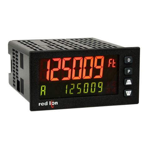
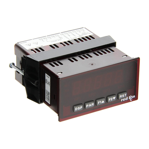
1. DISPLAY: 6 digit, 0.56" (14.2 mm) red sunlight readable or standard green
LED, intensity adjustable.
2. POWER:
AC Versions:
AC Power: 85 to 250 VAC, 50/60 Hz, 18 VA
Isolation: 2300 Vrms for 1 min. to all inputs and outputs. (300 V working)
DC Versions:
DC Power: 11 to 36 VDC, 14 W
(derate operating temperature to 40 °C if operating <15 VDC and three
plug-in option cards are installed)
AC Power: 24 VAC, ± 10%, 50/60 Hz, 15 VA
Isolation: 500 Vrms for 1 min. to all inputs and outputs (50 V working).
3. SENSOR POWER: 12 VDC, ±10%, 100 mA max. Short circuit protected
4. KEYPAD: 3 programmable function keys, 5 keys total
5. RATE DISPLAYS:
Maximum Display: 5-digits
Display Range: 0 to 99999 (Rate A or B); -9999 to 99999 (Rate C)
Over/Under Range Display: “”
Annunciators (displayed in Digit 6): - Rate A, - Rate B, - Rate C
Display Update Time: Adjustable 0.1 to 99.9 seconds
Maximum Frequency: See Maximum Signal Frequencies Table
Minimum Frequency: 0.01 Hz
Accuracy: ±0.01% of input signal frequency
6. TOTALIZER DISPLAYS:
Maximum Display: 8-digits
Display Range: ±99999999; For values greater than 6 digits, display
alternates between high order ( prefix) and low order digits.
Over/Under Range Display: “”
Annunciators: A, B and C along left side of display for selected Totalizer.
Maximum Frequency: See Maximum Signal Frequencies Table
Maximum Signal Frequencies Table
RATE ONLY (Totalizers A & B Disabled)
Single Rate (A or B) 44 KHz1(with or without setpoints)
Dual Rate (A & B) 19 KHz1(with or without setpoints)
DUAL RATE WITH
TOTALIZER(S) Single Totalizer
Enabled (A or B) Both Totalizers
Enabled (A & B)2
Setpoint(s) assigned to an
enabled Totalizer ? No Yes No Yes
TOTALIZER A or B
OPERATING MODE3Maximum Frequency in KHz4
Count x1 14 8.5 13 8.5
Count x2 14 8.5 10 7
Quadrature x1 9.5 9 8 4.5
Quadrature x2 9.5 8.5 7 4
Quadrature x4 9.5 5 N/A N/A
Notes:
1These values apply with or without Rate C Calculation enabled.
2If both Totalizers are used with different operating modes, then the lower
frequency listed applies to both Totalizers.
3See Programming Module 4 for Totalizer Operating Mode descriptions.
4Derate listed values by 15% if Totalizer C Calculation is enabled.
7. INPUTS A and B: DIP switch selectable to accept pulses from a variety of
sources including switch contacts, TTL outputs, magnetic pickups and all
standard Red Lion sensors.
Logic: Input trigger levels VIL = 1.5 V max.; VIH = 3.75 V min.
Current sinking: Internal 7.8 Kpull-up to +12 VDC, IMAX = 1.9 mA.
Current sourcing: Internal 3.9 Kpull-down, 7.3 mA max. @ 28 VDC,
VMAX = 30 VDC.
Filter: Damping capacitor provided for switch contact bounce. Limits
input frequency to 50 Hz and input pulse widths to 10 msec. minimum.
Magnetic Pickup:
Sensitivity: 200 mV peak
Hysteresis: 100 mV
Input impedance: 3.9 K@ 60 Hz
Maximum input voltage: ±40 V peak, 30 Vrms
Dual Count Modes: When any dual count mode is used, then User Inputs 1
and/or 2 will accept the second signal of each signal pair. The user inputs
do not have the Logic/Mag, HI/LO Freq, and Sink/Source input setup
switches. The user inputs are inherently a logic input with no low
frequency filtering. Any mechanical contacts used for these inputs in a
dual count mode must be debounced externally. The user input may only
be selected for sink/source by the User Jumper placement.
8. USER INPUTS: Three programmable user inputs
Max. Continuous Input: 30 VDC
Isolation To Sensor Input Commons: Not isolated
Logic State: Jumper selectable for sink/source logic
INPUT STATE SINKING INPUTS
5.1 Kpull-up to +12 V SOURCING INPUTS
5.1 Kpull-down
Active VIN < 0.9 VDC VIN > 3.6 VDC
Inactive VIN > 3.6 VDC VIN < 0.9 VDC
Response Time: 6 msec. typical; function dependent. Certain resets, stores
and inhibits respond within 25 μsec if an edge occurs with the associated
totalizer or within 6 msec if no count edge occurs with the associated
totalizer. These functions include , , , , and
. Once activated, all functions are latched for 50 msec min. to 100
msec max. After that period, another edge/level may be recognized.
9. MEMORY: Nonvolatile E2PROM retains all programmable parameters and
display values when power is removed.
10. CERTIFICATIONS AND COMPLIANCES:
SAFETY
IEC 61010-1, EN 61010-1: Safety requirements for electrical equipment
for measurement, control, and laboratory use, Part 1.
IP65 Enclosure rating (Face only), IEC 529
IP20 Enclosure rating (Rear of unit), IEC 529
ELECTROMAGNETIC COMPATIBILITY
Emissions and Immunity to EN 61326: Electrical Equipment for Measurement,
Control and Laboratory use.
Immunity to Industrial Locations:
Electrostatic discharge EN 61000-4-2 Criterion A
4 kV contact discharge
8 kV air discharge
Electromagnetic RF fields EN 61000-4-3 Criterion A
10 V/m (80 MHz to 1 GHz)
3 V/m (1.4 GHz to 2 GHz)
1 V/m (2 GHz to 2.7 GHz)
Fast transients (burst) EN 61000-4-4 Criterion A
2 kV power
1 kV I/O signal
2 kV I/O signal connected
to power
Surge EN 61000-4-5 Criterion A
power 1 kV L to L,
2 kV L to G
signal 1 kV
RF conducted interference EN 61000-4-6 Criterion A
3 Vrms
AC power EN 61000-4-11
Voltage dip Criterion A
0% during 1 cycle
40% during 10/12 cycle
70% during 25/30 cycle
Short interruptions Criterion C
0% during 250/300 cycles
Emissions:
Emissions EN 55011 Class A
Notes:
1. Criterion A: Normal operation within specified limits.
2. Criterion C: Temporary loss of function where system reset occurs.
Refer to the EMC Installation Guidelines section of the bulletin for
additional information.
11. ENVIRONMENTAL CONDITIONS:
Operating Temperature Range: 0 to 50 °C (0 to 45 °C with all three plug-in
cards installed)
Storage Temperature Range: -40 to 60 °C
Operating and Storage Humidity: 0 to 85% max. relative humidity non-
condensing
Altitude: Up to 2000 meters
12. CONNECTIONS: High compression cage-clamp terminal block
Wire Strip Length: 0.3" (7.5 mm)
Wire Gage: 30-14 AWG copper wire
Torque: 4.5 inch-lbs (0.51 N-m) max.
13. CONSTRUCTION: This unit is rated for NEMA 4X/IP65 outdoor use.
IP20 Touch safe. Installation Category II, Pollution Degree 2. One piece
bezel/case. Flame resistant. Synthetic rubber keypad. Panel gasket and
mounting clip included.
14. WEIGHT: 10.1 oz. (286 g)
Courtesy of Steven Engineering, Inc.-230 Ryan Way, South San Francisco, CA 94080-6370-Main Office: (650) 588-9200-Outside Local Area: (800) 258-9200-www.stevenengineering.com
