Hayward AQR100 User manual

USE ONLY HAYWARD GENUINE REPLACEMENT PARTS
Hayward Pool Products
620 Division Street, Elizabeth NJ 07207
Phone (908)-355-7995
www.hayward.com
AQR100
Chlorine Generator for Inground
Swimming Pools up to 30,000 gallons
Owner’s Manual
092735 RevB
AQR100
\Contents
Introduction................................2
Installation..................................3
Pool Chemistry............................9
Operation..................................12
Troubleshooting.........................15
Mounting Hole Template............18
Warranty....................................18

USE ONLY HAYWARD GENUINE REPLACEMENT PARTS
1
IMPORTANT SAFETY INSTRUCTIONS
When installing and using this electrical equipment, basic safety precautions should always be fol-
lowed, including the following:
• READ AND FOLLOW ALL INSTRUCTIONS
• TO REDUCE THE RISK OF DROWNING FROM HAIR AND BODY ENTRAPMENT, INSTALLA SUITABLY
RATED SUCTION GUARD TO MATCH THE MAXIMUM FLOW RATE MARKED. ATTENTION : LES
PRISES DASPIRATION DOIVENT ETRE EQUIPEES DE GRILLES CONVENANT AU DEBIT MAXIMAL
INDIQUE.
• WARNING: To reduce the risk of injury, do not permit children to use this product unless they
are closely supervised at all times.
• Do not bury cord. Locate cord to minimize abuse from lawn mowers, hedge trimmers, and other
equipment.
• WARNING: To reduce the risk of electric shock, replace damaged cord immediately.
• CAUTION: To reduce the risk of electric shock, install at least 10 feet (3 meters) horizontally from
the inside walls of a pool or spa/hot tub. Do not use an extension cord. ATTENTION : MAINTENIR
UNE DISTANCE MINIMALE D’UN METRE, MESUREE DANS UN PLAN HORIZONTAL, ENTRE LE
BASSIN ET LES APPAREILS ET COMMANDES.
• For Canadian Units: At least two lugs marked “BONDING LUGS” are provided on the external
surface or on the inside of the supply terminal box or compartment. To reduce the risk, con-
nect the local common bonding grid in the area of the hot tub or spa to these terminals with an
insulated or bare copper conductor not smaller than No. 6 AWG.
SAVE THESE INSTRUCTIONS

USE ONLY HAYWARD GENUINE REPLACEMENT PARTS
2
Introduction
The AQR100 is an automatic chlorine generation system for pool sanitization. It is designed for
inground swimming pools up to 30,000 gallons only. The AQR100 is NOT to be used with
above ground pools or with inground pools greater than 30,000 gallons.
The AQR100 requires a low concentration of salt (sodium chloride) in the pool water. It automatically
sanitizes your pool by converting the salt into free chlorine which kills bacteria and algae in the water.
Chlorine will revert back to sodium chloride after killing bacteria. These reactions will continuously
recycle virtually eliminating the need to add sanitizing chemicals to your pool.
The AQR100 can handle the purification needs of most residential swimming pools up to 30,000
gallons (113,000 liters). This unique low cost chlorine generator uses a replaceable electrolytic Cell
that is designed to last for one pool season.
NOTE: The actual amount of chlorination required to properly sanitize a pool varies due to bather
load, rainfall, temperature, and the pool’s cleanliness.
NOTE: Before installing this product as part of a saline water purification system in a pool or spa
using natural stone for coping or for immediately adjacent patios/decking, a qualified stone instal-
lation specialist should be consulted regarding the appropriate type, installation, sealant (if any) and
maintenance of stone used around a saline pool with electronic chlorine generator in your particular
location and circumstances.
NOTE: The use of dry acid (sodium bisulfate) to adjust pool pH is discouraged especially in arid regions
where pool water is subject to excessive evaporation and is not commonly diluted with fresh water.
Dry acid can cause a buildup of by-products that can damage your chlorinator Cell.

USE ONLY HAYWARD GENUINE REPLACEMENT PARTS
3
Installation
Remove power to the pool filter pump before starting this installation. Installation must be performed
in accordance with Local and NEC codes. The AQR100 can be powered by either 120 VAC or 240
VAC from the same circuit as the pool pump. Its 6 ft. power cord must be connected to power within
a junction box. The Control Box must be mounted a minimum of 10 ft. horizontal distance (or more, if
local codes require) from the pool and within 15 ft. from where the Cell will be installed. Take care to
protect the Cell Cap connector pins while handling the AQR100 unit during installation. If the supply
cord is damaged, it must be replaced by the manufacturer, its service agent or similarly qualified
persons in order to avoid a hazard.
Preparing Pool Water
To prepare the pool water for AQR100 operation, the pool’s chemistry must be balanced and salt
must be added. This must be done BEFORE activating the AQR100. Some adjustments to your pool
chemistry may take several hours, so start the procedure well before you intend to operate theAQR100.
To properly prepare your pool water for use with the AQR100, refer to the “Pool Chemistry” section
on page 9 of this manual.
Adding Salt: Add salt several hours or, if possible, 1 day prior to operating the AQR100. Take care
not to exceed the recommended salt level. Measure salt 6-8 hours after adding to the pool.
NOTE: If the pool does not have new water, add 1 quart (1 liter) of metal remover and 1 quart (1 liter)
of non-copper based algaecide to the pool, per manufacturer’s instructions. This ensures a quick,
troublefree transfer to the AQR100 system.
FROM
POOL
TO
POOL
FILTER
PUMP
FILTER
SOLAR
HEATER
CELL
VESSEL
POWER
CORD
UL LISTED
JUNCTION
BOX
15' CELL CABLE

USE ONLY HAYWARD GENUINE REPLACEMENT PARTS
4
Mounting the AQR100 Control Box
The AQR100 is contained in a raintight enclosure that is suitable for outdoor mounting. The Control
Box must be mounted a minimum of 10 ft. (4 meters) horizontal distance (or more, if local codes
require) from the pool and within 15 ft. from where the Cell is installed.
The Control Box is designed to mount vertically on a flat surface with the cables facing downward.
Because the enclosure also acts as a heat sink (disperses heat from inside the box), it is important
not to block the four sides of the Control Box. Do not mount the Control Box inside a panel or tightly
enclosed area.
Before securing the Control Box to the intended location, make sure that the Cell cable will reach the
location where the Cell Vessel will be installed. For mounting information, refer to the diagram below.
Select appropriate fasteners for your mounting surface that are suitable for a 20lb load.The mounting
template shown in Step 1 can be found on page 18.
Screw in top
fasteners leaving
1/8” space between
screw head and surface
Attach top mounting hole
guide to desired location and
drill mounting holes.
Hang Control Box
on fasteners and drill
bottom holes.
Screw in bottom
fasteners securely.
1
3
2
4
Located in
back of Manual

USE ONLY HAYWARD GENUINE REPLACEMENT PARTS
5
Plumbing
The Cell Vessel is designed to install in 2” (51mm) PVC pool plumbing. For pools using 1½” (38 mm)
polypipe, you must use a 2” adapter. The Cell Vessel must be installed on approximately 10” run of
straight pipe at the end of the return piping just before the water returns to the pool. All pool equip-
ment should be upstream from the Cell Vessel as shown in the diagram below. It must be located
within 15 feet of where the Control Box is mounted. Also, position the Vessel in a manner where the
Cell can be easily inserted and removed.
With power removed to the pump and water drained from the pool plumbing, cut the plumbing in the
desired location and glue the unions to the pipe. Install the included rubber gaskets on the Cell Vessel
then install the Cell Vessel into the plumbing by handtightening the unions.
Remove the foam protector from the Cell. Verify that the O-Ring is attached before inserting the Cell
into the Cell Vessel. Fully cover Cell pins with supplied grease as shown.
FROM
POOL
TO
POOL
Install gaskets on Cell
Vessel before installation
When choosing an
installation location, allow
enough cord to easily
insert/remove the cell
O-Ring
Grease

USE ONLY HAYWARD GENUINE REPLACEMENT PARTS
6
Connect and Fasten Cell Cap
Slip the Cell Cap through the Retaining Nut as shown below. Plug the Cell Cap into the Cell and
secure with the Retaining Nut.
Wiring
Power must be shut off at the circuit breaker before performing any wiring. Be sure to follow Local
and NEC electrical codes. To provide safe operation, the AQR100 should be installed by a qualified
service professional and must be properly grounded and bonded.
The AQR100 can be powered by either 120 VAC or 240 VAC and must be wired in a manner that
the AQR100 turns on and off with the pool pump. If the pump is connected to a timeclock or switch,
wire the AQR100 in parallel.
Locate the 6 ft. long five conductor cable coming from the Control Box. These five colored wires are
used to select voltage and apply power to the AQR100. Refer to the wiring label on the AQR100 as
well as the diagrams on the following page to determine correct wiring connections for either 120
VAC or 240 VAC. Cut the cable and conductors to length and ensure that all connections are made
within a UL Listed junction box. Attach the junction box cover when wiring is complete.
Cell Cap Retaining Nut

USE ONLY HAYWARD GENUINE REPLACEMENT PARTS
7
120 VAC
L1
Neutral
UL Listed
Junction Box
Power Cord from AQR100
black
&
violet
Ground
red
&
white
240 VAC
L1
UL Listed
Junction Box
L2
Power Cord from AQR100
white
&
violet
Ground
red
black

USE ONLY HAYWARD GENUINE REPLACEMENT PARTS
8
Bonding
Pool bonding or “equipotential bonding” ensures that all pool components around the pool are at the
same electrical potential. If bonding is required at your location (see Local and NEC codes), bonding
lugs are is provided at the bottom of the AQR100 enclosure. Run an 8 AWG solid copper wire (6 AWG
Canada) from the bonding lug to your pool’s existing bonding loop.
IMPORTANT: Before going any further, the pool water must be balanced and salt must be added to
your pool. If this has not already been done, refer to the “Pool Chemistry” section on page 9 of this
manual for information on how to prepare your pool water for AQR100 operation.
To Pool Bonding loop

USE ONLY HAYWARD GENUINE REPLACEMENT PARTS
9
Pool Chemistry
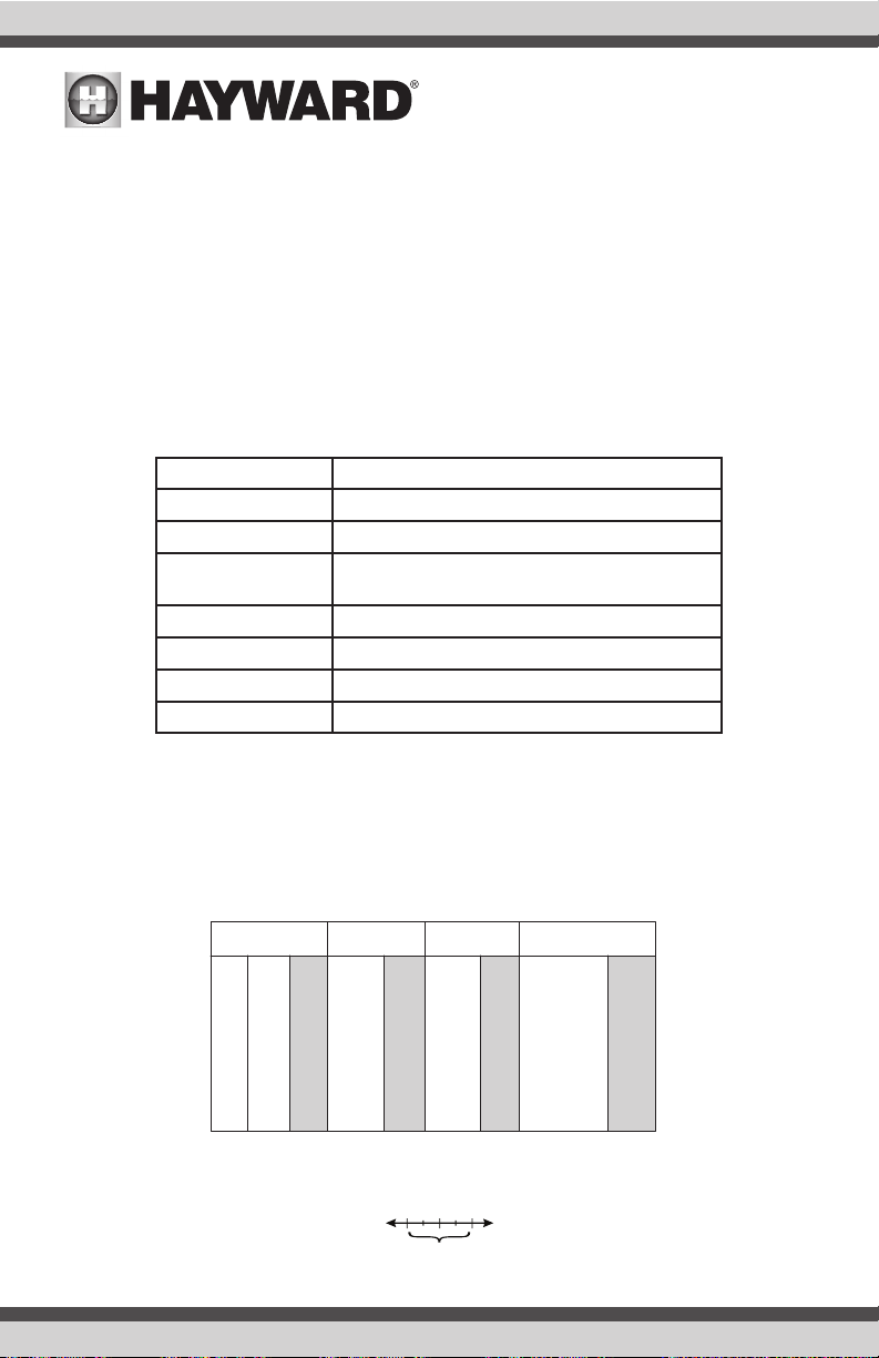
The table below summarizes the levels that are recommended by The Association of Pool and Spa
Professionals (APSP). It is important to maintain these levels in order to prevent corrosion or scaling
and to ensure maximum performance from your AQR100 chlorine generator. Your authorizedAQR100
dealer or most pool stores can provide you with the chemicals and procedures to adjust the water
chemistry as well.
Note that pool water emanating from wells and municipal water supplies, along with the introduction
of environmental contaminants, can contain chemistries that are deleterious to the life expectancy
of the Cell.
Salt 1500 to 4500 ppm (3200 ideal)
Free Chlorine 1.0 to 3.0 ppm
pH 7.2 to 7.8
Cyanuric Acid
(Stabilizer) Outdoor Pools 30-50 ppm
Indoor Pools - 0 ppm
Total Alkalinity 80 to 120 ppm
Calcium Hardness 200 to 400 ppm
Metals 0 ppm
Saturation Index -.2 to .2 (0 best)
Saturation index
The saturation index (Si) relates to the calcium and alkalinity in the water and is an indicator of the
pool water “balance”. Your water is properly balanced if the Si is 0 ± 0.2. If the Si is below -0.2,
the water is corrosive and plaster pool walls will be dissolved into the water. If the Si is above +0.2,
scaling and staining will occur. Use the chart below to determine the saturation index.
Si = pH + Ti + Ci + Ai - TDS
Hardness
Calcium
75
100
125
150
200
250
300
400
600
800
Total Dissolved
Solids
Total
alkalinity
°C °F Ti Ci Ai TDS
12
16
19
24
29
34
39
53
60
66
76
84
94
102
0.3
0.4
0.5
0.6
0.7
0.8
0.9
1.5
1.6
1.7
1.8
1.9
2.0
2.1
2.2
2.4
2.5
75
100
125
150
200
250
300
400
600
800
1.9
2.0
2.1
2.2
2.3
2.4
2.5
2.6
2.8
2.9
0-1000
1001-2000
2001-3000
3001-4000
4001-5000
12.10
12.29
12.35
12.41
12.44
Use: Measure the pH of the pool water, the temperature, water hardness, total alkalinity,
and total dissolved solids. Use the table above to determine Ti, Ci, Ai, and TDS in the
formula shown above. If the Si is equal to 0.2 or more, stains may appear. If the Si is
equal to -0.2 or less, corrosion or deterioration may occur.
Corrosion Stain
Ok
-0.2 0.2
CHEMICAL IDEAL LEVELS

USE ONLY HAYWARD GENUINE REPLACEMENT PARTS
10
Salt Level
Determining the optimal salt concentration for your pool should be based on your desired pump run
time and the size of your pool. Use the chart on page 11 to determine how much salt in pounds or
(Kgs) need to be added to reach the recommended levels. Use the equations below (measurements
are in feet/gallons and meters/liters) if pool size is unknown.
Gallons
(pool size in feet) Liters
(pool size in meters)
Rectangular Length x Width x Average Depth x 7.5 Length x Width x Average Depth x 1000
Round Diameter x Diameter x Average Depth x 5.9 Diameter x Diameter x Average Depth x 785
Oval Length x Width x Average Depth x 6.7 Length x Width x Average Depth x 893
The AQR100 is designed to operate with a salt level between 1500-4500 ppm (parts per million),
with 3200 ppm being ideal. This broad operating range offers the flexibility to use a salt level that
best suits your pool application. Note that lower salt levels will reduce the efficiency of the AQR100
and result in lower chlorine production. This lower chlorine production may require longer run times
to effectively sanitize the pool. If the pool is too large or the salt level too low, you may not produce
enough chlorine to meet your pool’s demand. In general,
• For pools up to 15,000 gallons, lower salt levels (1500 - 2700 ppm) may be used. Higher levels
can also be used and will require less operating time.
• For pools larger than 15,000 gallons and up to 30,0000 gallons, salt concentration should be
higher than 2800 ppm. Note that a high salt level can begin to give a salty taste to your pool
and can even cause the AQR100 to shut down. Generally, salt will begin to be tasted at a level
of about 3500-4000+ ppm.
The salt in your pool is constantly recycled and the loss of salt throughout the swimming season should
be small. This loss is due primarily to the addition of water because of splashing, backwashing, or
draining (because of rain). Salt is not lost due to evaporation.
Type of Salt to Use
It is important to use only sodium chloride (NaCl) salt that is greater than 99% pure. This is common
food quality or water softener salt and is usually available in 40-80 lb. bags labeled “Coarse Solar
Salt” or “Pool Salt”. It is also acceptable to use water conditioning salt pellets, however, it will take
longer for them to dissolve. Do not use rock salt, salt with yellow prussiate of soda, salt with anti-
caking additives, or iodized salt.
How to Add or Remove Salt
For new plaster pools, wait 10-30 days (check with you local pool professional) before adding salt to
allow the plaster to cure. Turn the circulating pump on and add salt directly into the pool. Brush the
salt around to speed up the dissolving process--do not allow salt to pile up on the bottom of the pool.
Run the filter pump for 24 hours with the suction coming from the main drain (use pool vac if there
is no main drain) to allow the salt to evenly disperse throughout the pool.
The only way to lower the salt concentration is to partially drain the pool and refill with fresh water.
Always check stabilizer (cyanuric acid), when checking salt. These levels will most likely decline
together. Use the chart on the following page to determine how much stabilizer must be added to
raise the level to 40 ppm.

USE ONLY HAYWARD GENUINE REPLACEMENT PARTS
11
Gallons and (Liters) of Pool Water
12,000 14,000 16,000 18,000 20,000 22,000 24,000 26,000
Current salt
level
(45000) (52,500) (60,000) (67,500) (75,000) (82,500) (90,000) (98,400)
ppm
0320
(145)
373
(170)
427
(194)
480
(218)
533
(242)
587
(267)
640
(291)
693
(315)
200 300
(136)
350
(159)
400
(182)
450
(205)
500
(227)
550
(250)
600
(273)
650
(296)
400 280
(127)
327
(148)
373
(170)
420
(191)
467
(212)
513
(233)
560
(255)
607
(277)
600 260
(118)
303
(138)
347
(158)
390
(177)
433
(197)
477
(217)
520
(236)
563
(256)
800 240
(109)
280
(127)
320
(145)
360
(164)
400
(182)
440
(200)
480
(218)
520
(236)
1000 220
(100)
257
(117)
293
(133)
330
(150)
367
(167)
403
(183)
440
(200)
477
(217)
1200 200
(91)
233
(106)
267
(121)
300
(136)
333
(152)
367
(167)
400
(182)
433
(197)
1400 180
(82)
210
(95)
240
(109)
270
(123)
300
(136)
330
(150)
360
(164)
390
(178)
1600 160
(73)
187
(85)
213
(97)
240
(109)
267
(121)
293
(133)
320
(145)
347
(157)
1800 140
(64)
163
(74)
187
(85)
210
(95)
233
(106)
257
(117)
280
(127)
303
(137)
2000 120
100
80
60
20
40
(55)
(45)
(36)
(27)
(9)
(18)
140
117
23
47
(64)
(53)
(11)
(21)
160
133
27
53
(73)
(61)
(12)
(24)
180
150
30
60
(82)
(68)
(14)
(27)
200
167
33
67
(91)
(76)
(15)
(30)
220
183
37
73
(100)
(83)
(17)
(33)
240
200
40
80
(109)
(91)
(18)
(36)
260
217
43
87
(118)
(99)
(19)
(39)
70
(32) 80
(36) 90
(41) 100
(45) 110
(50) 120
(55) 130
(60)
93
(42)
107
(48)
120
(55)
133
(61)
147
(67)
160
(73)
173
(79)
2200
3000
2800
2400
3200 Ideal Ideal Ideal Ideal Ideal Ideal Ideal Ideal
2600
3400 OK
OK OK
OK OK OK OK OK OK OK
POUNDS and (Kg) of SALT NEEDED FOR 3200PPM
3600+ Dilute Dilute Dilute Dilute Dilute Dilute Dilute Dilute
10,000
8,000
(37,500)
213 267
(97) (121)
200 250
(91) (114)
187 233
(85) (106)
173 217
(79) (98)
160 200
(73) (91)
147 183
(67) (83)
133 167
(61) (76)
120 150
(55) (68)
107 133
(48) (61)
93 117
(42) (53)
80 100
67 83
53 67
40 50
13 17
27 33
(36) (45)
(30) (38)
(24) (30)
(18) (23)
(6) (8)
(12) (15)
Ideal Ideal
Dilute Dilute
(30,000)
28,000 30,000
(106,000)
(113,500)
746
(339)
799
(363)
700
(319)
750
(342)
654
(299)
701
(326)
606
(276)
609
(296)
560
(254)
600
(272)
514
(234)
551
(251)
466
(212)
499
(227)
420
(192)
450
(206)
374
(169)
401
(181)
326
(147)
349
(157)
280
234
46
94
(127)
(107)
(20)
(42)
300
251
49
101
(136)
(114)
(21)
(45)
140
(65) 150
(70)
186
(85)
199
(91)
Ideal Ideal
OK OK
Dilute Dilute
POUNDS and (Kg) OF STABILIZER (CYANURIC ACID) NEEDED FOR 40 PPM
Gallons and (Liters) of Pool Water
Current
Stabilizer
level
(ppm)
0 ppm
20 ppm
30 ppm
40 ppm
10 ppm
12,000
(45000)
8,000
(30000)
14,000
(52500)
10,000
(37500)
16,000
(60000)
18,000
(67500)
20,000
(75000)
20,000
(97500)
22,000
(82500)
28,000
(105000)
24,000
(90000)
30,000
(112500)
4.0
(1.8)
2.7
(1.2)
0.0 0.0
2.7
(1.3)
4.7
(2.2)
3.4
(1.5)
4.0
(1.8)
5.4
(2.5)
6.0
(2.7)
4.0
(1.8)
4.9
(2.2)
6.7
(3.0)
8.7
(4.0)
7.4
(3.4)
9.4
(4.3)
8.0
(3.6)
10.0
(4.5)
3.0
(1.4)
2.0
(.9)
3.5
(1.6)
2.5
(1.1)
4.5
(2.0)
5.0
(2.3)
6.5
(3.0)
5.5
(2.5)
7.0
(3.2)
6.0
(2.7)
7.5
(3.4)
2.0
(.90)
1.3
(.59)
0.0
2.3
(1.1)
1.7
(.77)
3.0
(1.3)
3.3
(1.5)
4.3
(2.0)
2.0
(.91)
2.6
(1.2)
3.7
(1.6)
4.6
(2.1)
1.0
(.45)
0.7
(.31)
1.2
(.54)
0.8
(.36)
1.4
(.64)
1.7
(.77)
2.2
(.97)
0.0 0.0
1.5
(.68)
1.8
(.82)
2.4
(1.1)
0.00.0 0.00.0 0.0 0.0 0.0

USE ONLY HAYWARD GENUINE REPLACEMENT PARTS
12
Operation
Controls
The main controls and indicators are shown below.
Illuminates when Cell has reached the end of its expected life.
When this LED indicator is illuminated, there is a problem with
the unit. Refer to the Troubleshooting section of this manual.
Illuminates when unit is waiting for the filter pump to turn on or
is in-between generating cycles as part of normal operation to
maintain selected .DAILY CHLORINE OUTPUT
Illuminates when unit is actively generating chlorine.
Illuminates when unit is SUPER CHLORINATING.
Illuminates when there is no flow or low flow through the
Cell. The pool filter pump could be in its “off” cycle. If this
is not the case, refer to the Troubleshooting section in
this manual.
Blinks when performing the Flow Switch Calibration
procedure.
When you have an abnormally high bather load, a large
amount of rain, a cloudy water condition, or any other
condition which requires a large amount of purification to
be introduced, press the button.
This electronically “super chlorinates” (boosts chlorine
generation output) the water for 24 hours (filter pump must
be on during this time). To cancel , pres
button again.
SUPER CHLORINATING
super chlorinating s
the SUPER CHLORINATING
Press ( + ) and ( - ) to increase or decrease the chlorine
generation. The DAILY CHLORINE OUTPUT LEDs
above these buttons will indicate the relative amount of
chlorine being generated.

USE ONLY HAYWARD GENUINE REPLACEMENT PARTS
13
Operation
When power is first applied to the AQR100, an initialization routine will run and during this time, vari-
ous LEDs will illuminate. This is perfectly normal and does not require any input from the user. When
the routine is finished, the AQR100 will begin normal operation.
If the water chemical levels are in the recommended range, there are three factors that you can control
which directly contribute to the amount of chlorine the AQR100 will generate:
1. filter time each day (hours)
2. the DAILY CHLORINE OUTPUT setting
3. the amount of salt in the pool
The filter pump timer/schedule should be set so that all of the water in the pool passes through the
filter at least once each day. For pools with high chlorine demand, the timer may have to be set
longer to generate enough chlorine.
Daily Chlorine Output Setting
You can adjust the amount of chlorine that is generated using the “+” and “-” button on the AQR100
unit. The DAILY CHLORINE OUTPUT LEDs will display the current setting. Push “+” to increase and “-”
to decrease the current setting. Each DAILY CHLORINE OUTPUT LED represents 6 minutes of chlorine
generation out of 1 hour. For example,if 5 LEDs are illuminated,theAQR100 unit will generate chlorine
for 5 x 6 = 30 minutes out of every hour of operation. During this time, the GENERATING CHLORINE
LED will be lit. The unit will be idle for the remaining 30 minutes at which time the GENERATING
CHLORINE LED will turn off and the STANDING BY LED will illuminate.
To find the optimum setting,start the operation with 5 DAILY CHLORINE OUTPUT LEDs illuminated. Test
the chlorine level every few days and adjust up or down accordingly. It usually takes 2-3 adjustments
to find the ideal setting for your pool and after that, it should only take minor, infrequent adjustments.
Because the chlorine demand of the pool increases with temperature, most people find they have to
adjust up at the peak of the summer and down during colder periods. The AQR100 automatically
scales back to 12 minutes of output per hour (if set higher than 12 minutes) when the pool water
is 50º - 60ºF. This protects the unit as well as prevents possible over-chlorination. The AQR100
stops generating when the pool water temperature drops below 50ºF. This is usually not a problem
because bacteria and algae stop growing at this temperature. You can override these automatic low
temperature operations by switching to SUPER CHLORINATE for a day.
NOTE: After the ideal DAILY CHLORINE OUTPUT setting has been found, you may need to raise the
setting when the pool water temperature increases significantly, when there is higher than normal
bather load or when the AQR100 Cell ages. You may need to lower the setting when the pool water
temperature decreases significantly or there are long periods of inactivity.
Prevent over-chlorination during cold weather: Check chlorine levels periodically. Most pools
require less chlorine during cold weather and the DAILY CHLORINE OUTPUT should be lowered
accordingly.
Maintaining the AQR100 System
The replaceable Cell uses the same electronic self cleaning technology as the popular Hayward
Turbo Cell. In most cases this self cleaning action will keep the Cell working at optimum efficiency.

USE ONLY HAYWARD GENUINE REPLACEMENT PARTS
14
In areas where water is hard (high mineral content) and in pools where the water chemistry has
been allowed to get “out of balance,” the Cell may require periodic cleaning.
Servicing and Cleaning the AQR100 Cell
Remove power from the AQR100 and the pump before attempting to remove the Cell. Unplug the
Cell cord from the Cell. Remove the Cell from the Vessel by unscrewing the Retaining Nut and gen-
tly pulling the Cell out of Vessel. Once removed, look inside the Cell and inspect for scale formation
(light colored crusty or flaky deposits) on the plates and for any debris which has passed through
the filter and caught on the plates. If no deposits are visible, reinstall. If deposits are seen, use a
high pressure garden hose and try to flush the scale off. If this is not successful, use a plastic or
wood tool (do not use metal as this will scratch the coating off the plates) and scrape deposits off
of plates. Note that a buildup on the Cell indicates that there is an unusually high calcium level in
the pool (old pool water is usually the cause). If this is not corrected, you may have to periodically
clean the Cell. The simplest way to avoid this is to bring the pool chemistry to the recommended
levels as specified.
Mild Acid Washing: Use only in severe cases where flushing and scraping will not remove the
majority of deposits. To acid wash, mix a 4:1 solution of water to muriatic acid (one gallon of water
to one quart of muriatic acid) in a clean plastic container. ALWAYS ADD ACID TO WATER - NEVER
ADD WATER TO ACID. Be sure to wear rubber gloves and appropriate eye protection.
Place the Cell in a clean container. The Cell can become
unstable when the solution is added so it is recom-
mended that a smaller container be used. Add the solu-
tion to the level as shown. The solution should cover the
plates but not be so high that the cylindrical electronics
compartment is submerged. Soak the Cell for a few
minutes and then rinse with a high pressure garden
hose. If any deposits are still visible, repeat soaking and
rinsing. Replace Cell and inspect again periodically.
Winterizing
The AQR100 replaceable Cell will be damaged by freez-
ing water just as your pool plumbing would. In areas of
the country which experience severe or extended periods of freezing temperatures, be sure to drain
all water from the pump, filter, and supply and return lines before any freezing conditions occur.
The Control Box and plumbed in Cell Vessel are capable of withstanding any winter weather and
should not be removed.
Spring Start-up
DO NOT turn the AQR100 on until the pool water chemistry has been brought to the proper levels.
This information can be found on page 9.

USE ONLY HAYWARD GENUINE REPLACEMENT PARTS
15
Troubleshooting
Visit www.hayward.com or call (908)-355-7995 for helpful information on operation, maintenance
and troubleshooting your AQR100 Electronic Chlorine Generator.
Common Problems and Solutions
The AQR100’s various LEDs show the operation status as well as alert the user to any problems
that may have occurred. Some indications may require a combination of LEDs to illuminate. To aid
in interpreting these indications, Hayward has created an interactive tool located at www.hayward.
com. Use this tool and the information below to identify and correct problems that may arise.
1. Possible causes of little or no free chlorine residual
• DAILY CHLORINE OUTPUT adjustment setting is too low
• Low stabilizer (Cyanuric Acid)
• Filter pump time too short (8 hours for average size pools, more for large pools)
• Salt level too high
• Very warm pools increase chlorine demand--increase Output %, or filter run time
• Cold water below 50ºF causes AQR100 to stop generating
• Cold water between 50ºF - 60ºF causes AQR100 to reduce output regardless of DAILY
CHLORINE OUTPUT setting
• Excessive scaling on Cell.
• High level of Nitrogen in pool water.
• “Yellow Out” or similar treatment recently used. Some yellow algae treatments will use
chlorine at a very high rate and deplete the residual free chlorine. Manually shock the
pool if indicated in the directions on the algae treatment. It still may be a matter of days
before the pool returns to “normal” and chlorine tests will show the desired 1-3 ppm free
chlorine reading.
2. LEDs not on
Depending on current conditions, there should always be at least one LED illuminated when
the AQR100 is powered. If no LEDs are on, check to make the unit is receiving power. If no
power is detected, the circuit breaker may have to be reset.
3. STANDING BY LED blinking
The AQR100 has shut down because the temperature of the pool/spa water is too high
(120ºF) or too low (50ºF). The system will not resume operation until the water temperature
returns to normal. NOTE: This condition can sometimes happen if the pool/spa temperature is
already high and the heater is running. The temperature coming out of the heater and into the
Cell could possibly be high enough to shut down the AQR100.
4. INADEQUATE WATER FLOW LED illuminated
The AQR100 has sensed a low flow or no flow condition and has stopped generating chlorine.
• Verify that the filter pump is running and there are no obstructions or restrictions in the
pool plumbing.
• Backwash the pool filter.
• Increase the speed of your variable speed pump

USE ONLY HAYWARD GENUINE REPLACEMENT PARTS
16
If the condition persists, remove the Cell from the Vessel and check that the flow switch is free to
move in both directions. Refer to the diagram below.
5. CELL LIFE LOW LED illuminated
The Cell has reached the end of its life. Replace as soon as possible
6. PROBLEM DETECTED LED illuminated AND MAX LED blinking
There is a communication error with the Cell. Check that the Cell cap is properly plugged in
and that the wire to the Control Box is not cut or damaged.
7. PROBLEM DETECTED LED illuminated AND MIN LED blinking
• The salt level may be too low. Adjust salt to recommended levels.
• Remove and inspect the Cell for scale. If the Cell is scaled, follow the directions on page
14 for Cell cleaning.
8. PROBLEM DETECTED LED illuminated AND a DAILY CHLORINE OUTPUT LED is blinking
The AQR100 may display an error by illuminating the PROBLEM DETECTED LED and blinking
one of the DAILY CHLORINE OUTPUT LEDs. There are ten DAILY CHLORINE OUTPUT LEDs that
each indicate a different error. These LEDs are labeled with a number on the diagram below.
Refer to the table for their corresponding errors.
STANDING BY
GENERATING
CHLORINE
SUPER
CHLORINATING
PROBLEM
DETECTED
CELL LIFE LOW
INADEQUATE
WATER FLOW
TEST WATER REGULARLY - SET OUTPUT TO
MAINTAIN 1-3 PPM AVERAGE CHLORINE
SUPER
CHLORINATE
MIN
MAX
USE SUPER CHLORINATE
FOR TEMPORARY OUTPUT BOOST
DAILY CHLORINE
OUTPUT
1
2
3
4
5678910
S
Flow Switch

USE ONLY HAYWARD GENUINE REPLACEMENT PARTS
17
Min LED Low Salt
1. Check the salt level in the pool and verify the salt level is greater
than 1500 ppm but also less than 4500 ppm.
2. Inspect the Cell. If dirty, follow the Cell cleaning procedure.
3. Inspect the Cell Vessel and verify the Cell plates are fully covered
by moving water.
4. Remove power to the AQR100 for two minutes and then re-apply.
LED 2 High Salt 1. Check that the salt level in the pool is no greater than 4500 ppm
and/or the temperature does not exceed 104ºF.
2. Remove power to the AQR100 for two minutes and then re-apply.
LED 3 Low
Input
Power
1. Remove power to the AQR100 for two minutes and then re-apply.
2. Verify that the AQR100 is input power wiring is correct (page 7).
Make sure that there is adequate input voltage (a brown out condi-
tion could cause this error).
LED 4 Temperature
Sensor Error 1. Remove power to the AQR100 for two minutes and then re-apply.
2. Inspect the Cell. If dirty, follow the Cell cleaning procedure.
LED 5
LED 6
LED 7
LED 9
Internal
Error
1. Remove power to the AQR100 for two minutes and then re-apply.
2. Check that the salt level in the pool is no greater than 4500 ppm
and/or the temperature does not exceed 104ºF.
3. Inspect the Cell Vessel and verify the cell plates are fully covered
by moving water.
4. Contact Hayward Technical Service.
LED 8 No Current
to Cell
1. Remove power to the AQR100 for two minutes and then re-apply.
2. Inspect the cable that connects the cell to the system. Make sure
the cable is secure and undamaged.
3. Turn on Super Chlorinate briefly and go back to original setting.
4. Inspect the Cell Vessel and verify the cell plates are fully covered
by moving water.
MAX LED Cell Error
1. Remove power to the AQR100 for two minutes and then re-apply.
2. Inspect the cable that connects the cell to the system. Make sure
the cable is secure and undamaged.
3. Contact Hayward Technical Service.
Inadequate
Water Flow
Low Flow
or
No Flow
Condition
1. Remove power to the AQR100 for two minutes and then re-apply.
2. Check for obstructions or a flow related cause in your pool’s plumb-
ing system.
Standing By Water
Temperature
Error
1. Remove power to the AQR100 for two minutes and then re-apply.
2. Check that the pool temperature is more than 50ºF and less than
104ºF.
Led
Blinking Possible Actions
Possible
Cause

USE ONLY HAYWARD GENUINE REPLACEMENT PARTS
18
LIMITED WARRANTY (effective 03/01/12) Hayward warrants its AQR100 chlorination products to be free of defects in
materials and workmanship, under normal use and service as follows:
Control Box - 3 year limited warranty, parts only
Cell - 3 years
Hayward warrants all accessories and other replacement parts for the above-identified chlorination products for a
period of one (1) year.
Each of these warranties is not transferable and applies only to the original owner.
Proof of purchase is required for warranty service. If written proof of purchase is not provided, the manufacturing date
code will be the sole determinant of the date of installation of the product. To obtain warranty service or repair, please
contact the place of purchase or the nearest Hayward authorized warranty service center. For more information on
authorized service centers please contact the Hayward Technical Service Support Center (61 Whitecap Road, North
Kingstown RI, 02852) or visit the Hayward website at www.hayward.com.
WARRANTY EXCLUSIONS:
1. Damage resulting from improper installation including installation on pools larger than the product rating.
2. Problems resulting from failure to install, operate or maintain the product(s) in accordance with the recommenda-
tions contained in the owners manual(s).
3. Problems resulting from failure to maintain pool water chemistry in accordance with the recommendations in the
owners manual(s).
4. Problems resulting from tampering, accident, abuse, negligence, unauthorized repairs or alternations, fire, flood,
lightning, freezing, external water, degradation of natural stone used in or immediately adjacent to a pool or spa,
war or acts of God.
DISCLAIMER. THE EXPRESS LIMITED WARRANTIES ABOVE CONSTITUTE THE ENTIRE WARRANTIES WITH RESPECT
TO THE ABOVE-IDENTIFIED HAYWARD POOL AUTOMATION AND CHLORINATION PRODUCTS AND IS IN LIEU OF ALL
OTHER WARRANTIES, EXPRESS OR IMPLIED, INCLUDING WARRANTIES OF MERCHANTABILITY OR FITNESS FOR A
PARTICULAR PURPOSE. THESE WARRANTIES GIVE YOU SPECIFIC LEGAL RIGHTS, AND YOU MAY ALSO HAVE OTHER
RIGHTS OF EQUIPMENT, LOST PROFITS OR REVENUE, COSTS OF RENTING REPLACEMENTS, AND OTHER ADDITIONAL
EXPENSES, EVEN IF THE SELLER HAD BEEN ADVISED OF THE POSSIBILITY OF SUCH DAMAGES. SOME STATES DO
NOT ALLOW THE EXCLUSION OF LIMITATION OF INCIDENTAL OR CONSEQUENTIAL DAMAGES, SO THE ABOVE LIMITA-
TION OR EXCLUSION MAY NOT APPLY TO YOU.
NO WHOLESALER, AGENT, DEALER, CONTRACTOR OR OTHER PERSON IS AUTHORIZED TO PROVIDE, SUPPLEMENT
OR MODIFY ANY WARRANTY ON BEHALF OF HAYWARD.
THESE WARRANTIES ARE VOID IF THE PRODUCT HAS BEEN ALTERED IN ANY WAY AFTER LEAVING THE FACTORY. FOR
THE ABOVE-IDENTIFIED CHLORINATION PRODUCTS, THESE WARRANTIES ALSO ARE VOID IF, DURING THE WARRANTY
PERIOD, YOU USE A REPLACEMENT CHLORINATOR CELL OTHER THAN AN UNMODIFIED, NEW HAYWARD CHLORINA-
TOR CELL PURCHASED FROM HAYWARD. IF A WARRANTY BECOMES VOID, YOU STILL MAY PURCHASE SERVICE AND/
OR TELEPHONE TECHNICAL SUPPORT AT THE THEN CURRENT TIME AND MATERIAL RATES.
Use to mount
on flat surface
Use to mount
on post
make sure holes are level before drilling

USE ONLY HAYWARD GENUINE REPLACEMENT PARTS
For further information or consumer
technical support, visit our website at
www.hayward.com
Hayward is a registered trademark and AQR100 is a
trademark of Hayward Industries, Inc. © 2019 Hayward Industries, Inc.
All other trademarks not owned by Hayward are the property of their respective owners.
Hayward is not in any way affiliated with or endorsed by those third parties.
Other manuals for AQR100
2
Table of contents
Languages:
Other Hayward Inverter manuals